Article

Snake-Like Robot with Fusion Gait for High Environmental Adaptability: Design, Modeling, and Experiment

1
Department of Instrument Engineering, Shanghai Jiao Tong University, Shanghai 200240, China
2
Department of Robotics, Ritsumeikan University, Kyoto 525-8577, Japan
*
Author to whom correspondence should be addressed.
Appl. Sci. 2017, 7(11), 1133; https://doi.org/10.3390/app7111133
Submission received: 22 September 2017 / Revised: 30 October 2017 / Accepted: 31 October 2017 / Published: 3 November 2017
(This article belongs to the Special Issue Bio-Inspired Robotics)

Abstract

:
A snake changes its gait to adapt to different environments. A snake-like robot that is able to perform as many or more gaits than a real-life snake has the potential to successfully adapt to a range of environments, similar to a real-life snake. However, only a few mechanisms in the current snake-like framework can perform common gaits. In this paper, a novel snake-like robot is developed to resolve this problem. A multi-gait is established and used as a reference for the articulation design. A non-snake-like mechanism with linear articulation is combined with the classical swing joint. A prototype is designed and constructed for verification and analysis. Two basic main gaits, namely, serpentine and rectilinear locomotion, are fused, and a novel obstacle-aided locomotion based on rectilinear motion is developed. The experiment demonstrates that the robot can generate all of the expected gaits with high movement efficiency.

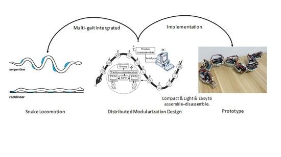
Graphical Abstract

1. Introduction

A snake is a reptile that has been evolving for more than 130 million years. Snakes have good motion adaptability and powerful attack capability on land and in water despite their simple string-like bodies. Researchers have explored and applied smart mechanisms that are based on snakes, including active cord mechanism (ACM) and Crawler robots, to emulate the unique motion of snakes, such as serpentine and rectilinear locomotion. A snake-like robot is often equipped with terrain adaptability by means of wheel or foot locomotion. Additionally, a slender body acts like a string and can enter narrow spaces. The unique motion of snake-like robots can generate the action of a hand and a leg [1]. Thus, snake-like robots can be successfully applied in nonstructural environments, such as disaster rescue, human body cavity examination, and industrial pipe inspection [2,3].
Hirose studied and developed many snake-like robots with ACM, a recent version of which is the ACM-R5 with amphibious features [4]. Ma completed a series of explorations of 3D snake-like locomotion, including works on a 3D joint mechanism and dynamics analysis [5,6]. However, passive wheels can limit adaptability and complicate locomotion, such as during disasters or in mud puddles. Thus, some researchers shifted to wheel-less snake-like robots, whereas others focused on crawler robots with additional functions. Bayraktaroglu reported a wheel-less robot with obstacle-aided locomotion [7]. Transeth presented a system for modeling and controlling a limbless snake-like robot [8]. Kuwada designed a snake-like robot with a rotary connection between swing joints that can be utilized for pipe inspection [9]. Other works focused on wheel-less snake-like robots, such as those by Crespi and Klaassen [10,11]. Crawler robots that can enter highly complicated environments have also been studied [3].
Wheel-less snake-like robots generally have high environmental adaptability but at the cost of motion efficiency. That is, they have high power consumption and low motility. Active crawler robots are bulky and have poor trafficability. However, in the natural world, snakes move with different gaits in different environments. Most of the current research focuses on classical serpentine locomotion, which is the most efficient type of motion. Few works concentrate on side-winding, concertina, and rectilinear types of movement. For example, the ACM-R3 can execute serpentine, rolling, and 3D motion [12]. The SIA (Shenyang Institute of Automation) snake-like robot can move in a helical gait in 3D space [13]. If a snake-like robot is configured with 2-DOF (Degree of Freedom) swing joints, then it can perform serpentine and side-winding motions but not concertina and rectilinear motions related to contractions and extensions. Meanwhile, a worm moves by shortening and elongating its body. In special cases, worm-like motion is superior, such as in terms of adaptability to narrow spaces, as it can avoid regular shape points. Thus, a 2-DOF joint with linear translation was developed for configuring a snake-like robot. This robot can easily realize serpentine and rectilinear gaits. Moreover, a solution related to multi-gait realization and kinematics analysis was discussed in our laboratory. As preliminary work, a prototype was proposed and experiments were performed [14,15].
On the basis of the preliminary findings, a 2-DOF joint with linear translation was developed and a snake-like robot was configured for the present study. A prototype was then designed and constructed for verification and analysis. Two basic main gaits, namely, serpentine and rectilinear locomotion, were fused, and a novel obstacle-aided locomotion based on rectilinear motion was developed.
This paper is organized as follows. Section 2 analyzes the classical gait of snakes and determines the DOF design of joints. Then, a method for realizing these gaits is introduced. On this basis, the details of the joint mechanism for the prototype and its control system are discussed. Section 3 explains the experiment verification and results. Finally, the conclusions and the discussion are outlined in Section 4.

2. Methods

2.1. Gait Analysis

The anatomy of a snake features hundreds of short globe articulations; this structure is difficult to fully reproduce in mechanical systems given the current technical limitations. Most snake-like robots are composed of 1- or 2-DOF swing joint serials. However, a simplistic mechanism leads to limited functions (i.e., few gaits). In nature, snakes commonly have four types of locomotion gaits: serpentine, side-winding, rectilinear, and concertina. However, locomotion gaits that have not been observed in nature have been realized. This paper excludes non-natural gaits and instead focuses on serpentine and rectilinear locomotion, which are the basic gaits that allow a robot to adopt different gaits according to the environment.
Snakes adopt the graceful and aesthetically pleasing serpentine locomotion when they are on grass or irregular plains. The whole body is thrust into several sinusoidal curves, with some body parts following the path of the head. The serpentine motion is shown in Figure 1a.
Rectilinear motion is common among boas, which have big bodies. As shown in Figure 1b, the front of the body is pressed against the ground as the rear part is extended by muscle release. In addition, the front is fixed on the ground while the remaining parts are pulled forward by muscle contraction. Although rectilinear locomotion is slow and motion-inefficient, it allows a snake to pass through narrow line-typed or circular-shaped pipes, in which other gaits cannot be realized.

2.2. Kinematics of Locomotion Gaits

The articulation modules in the snake-like robot are connected in serial, as shown in Figure 2. The world coordinate system xyz is fixed in extern with origin O. Absolute position and attitude are denoted by the head or tail point coordinate (x, y, z) in xyz and the inner body shape, respectively. To describe shape, a series of moving coordinates x1y1z1, x1y1z1, …, xnynzn is designated at every module from tail to head. Variables On+1 and O0 represent the head and the tail endpoints, respectively. The i-th moving coordinate xiyizi in the i-th module is constructed similar to Figure 2. Variable yi is the pitch joint axis, and zi is the roll joint axis. The origin is designated as the crossing point of yi and zi. The positive direction of zi is determined on the basis of the contraction of the linear joint. Variable xi is determined by the left-hand law of the Cartesian coordinate system. If the robot is shaped into a line, then xi and yi (i = 1, 2, …, n) are parallel to each other and all zi (i = 1, 2, …, n) are collinear. Variables li, γi, and θi denote the i-th translational displacement, roll angle, and pitch angle, respectively. The transformation of two adjacent module coordinates can be calculated as follows:
T i 1 i = R y R z P z = [ C θ i 0 S θ i 0 0 1 0 0 S θ i 0 C θ i 0 0 0 0 1 ] [ C γ i S γ i 0 0 S γ i C γ i 0 0 0 0 1 0 0 0 0 1 ] [ 1 0 0 0 0 1 0 0 0 0 1 l i 0 0 0 1 ] = [ C θ i C γ i C θ i S γ i S θ i l i S θ i S γ i C γ i 0 0 S θ i C γ i S θ i S γ i C θ i l i C θ i 0 0 0 1 ]
Equation (1) can be used to compute the coordinates of every joint point. Variables li, γi, and θi are used as inputs for the robot shape, which is related to gait. Kinematic analysis was performed to identify the best control input law and to establish the snake gait. The succeeding section shows the creation of the mathematical model of each gait on the basis of the aforementioned coordinate system and the mechanism.

2.2.1. Serpentine Gait

Serpentine gait is obtained by tracing the movement of a snake on a plane. The snake body is shaped into a serpentine curve. If the joint swings are modulated by the curvature function of the serpentine curve, then the snake can move forward continuously and gracefully. The serpentine curve is given by
{ x ( s ) = 0 s cos ( ξ σ ) d σ y ( s ) = 0 s sin ( ξ σ ) d σ
where ξ σ   = a · cos ( b · σ ) + c · σ , a, b, and c are the parameters used to determine the amplitude, frequency, and direction of the curve, respectively, and s is the curve length from the origin to the point (x, y). The curvature is expressed by
κ ( s )   = ( d 2 x d s 2 ) 2 +   ( d 2 y d s 2 ) 2 =   | a · b · sin ( b · s )   c |   .
Snake-like robots differ from natural snakes because the rigid links in robots are longer than those in real snake joints. In many prototypes, a serpentine is often approximated by discrete fold lines. Consequently, two solutions are suggested in Figure 3. As shown by the solid fold line, all joint points are located along the curve when passive wheels are installed on the joint point; this method is called the section method. When the wheels are defined along the link tangent center with the serpentine, the abovementioned discrete method is denoted by an imaginary fold line; this process is then called the tangent method. During joint point motion, the joint angle is designated as the control input. Assuming that the robot moves on a plane, our design should therefore determine θi (i = 1, 2, …, n).
In the section method, the total snake length is normalized to 1 such that the link length l is 1/n. A discrete equation of (2) is used to calculate the angle.
{ x i   = k = 1 i 1 n · cos ( a · cos ( k · b n )   +   k · c n ) y i   = k = 1 i 1 n · sin ( a · cos ( k · b n )   +   k · c n )
where (xi, yi) is the i-th coordinate of the joint in xoy and l is the link length. If we normalize l to 1, the joint angle can be easily calculated as follows:
θ i   =   arctan y i     y i 1 x i     x i 1     arctan y i + 1     y i x i + 1     x i   =   α · sin ( i β   +   β 2 )   +   γ
where
α   =   2 a sin ( β 2 ) ,   β   =   b n ,   γ   =   c n .

2.2.2. Rectilinear Gait

The locomotion of a snake-like robot with swing joints is characterized by motion singularity when its body is shaped into a line or an arc. The robot gait presented in this paper can resolve the aforementioned limitation. Linear joints play an important role in gaits. The locomotion of a robot composed of three articulation modules and a head cabin is shown in Figure 4. In the figure, 1, 2, and 3 denote pitch joints; I, II, and III represent links that change lengths as linear joints; and 0 is the head cabin. Only 0, 1, 2, and 3 touch the ground. In the same figure, the stroke along the line indicates motion from Phase A to E. First, Link I is extended while others are kept static. Then, the head cabin, 0, is pushed forward in Phase A. Link I contracts and Link II extends, thus pushing Joint 1 to Phase B. A similar action happens in Phase C, and Joint 2 advances. Finally, Joint 3 is pulled forward as Link III contracts. The robot advances Δs in this case. Phase E has the same configuration as A. Thus, the robot is continuously thrust forward through repetition.
The rectilinear gait is similar to the inchworm-like motion adopted by many worms. The force balance condition should be analyzed because gait can be realized only when partial articulation modules move while others are kept stationary. We assume that a joint in any articulation module is locked until the motors are powered. In the present study, analysis is performed in the quasi-static condition. The robot is composed of n articulation modules with identical masses. Subsequently, a general case is selected for the analysis. The i-th module moves at the speed of v, while others are kept stationary. Then, the i-th module is isolated from the mechanism. The equation for rectilinear gait in linear motion is as follows:
{ F i 1   = k = 1 i 1 f k     ( i   1 ) · m g · μ s F i 1   +   F   i   =   f i =   m g · μ d F i   = k = i + 1 n f k     ( n     1 ) · m g · μ s
where Fi is the pulling force that i − 1-th module applies on the i-th module, Fi+1 is the pulling force that i + 1-th module applies on the i-th module, Fi and Fi+1 are the counteracting forces of Fi and Fi+1, respectively, fk is the static friction of the rolling shaft in the passive wheels if kI, fi is the kinetic friction force of the rolling shaft, and μs and μd are the static and kinetic friction coefficients of the rolling shaft, respectively. The equation can be simplified by
μ d     ( n     1 ) · μ s .
Equation (7) can be satisfied theoretically when n ≥ 2. In real motion, the i-th module always starts with acceleration; in this case, the robot may slip because the condition cannot be assured. However, if we control acceleration and configure additional modules for the robot, adequate locomotion may still be achieved.

2.2.3. Obstacle-Aided Locomotion

To further improve the motion efficiency of snake-like robots in narrow and limited spaces, a novel gait called obstacle-aided locomotion is proposed for rectilinear locomotion. Obstacle-aided locomotion is an important way for biological snakes moving through an ill-conditioned environment and was explained in [8] as follows. “The fastest biological snakes exploit roughness in the terrain for locomotion. They may push against rocks, branches, or other obstacles to move forward more efficiently.” In obstacle-aided locomotion, the snake-like robot utilizes external objects, such as walls, stones, and other obstacles, for propulsion [16]. In narrow paths, both side walls serve as a fulcrum. Following earlier discussions on rectilinear locomotion, the novel gait is then represented visually, as shown in Figure 5.
In the initial state, each joint of the snake-like robot is set in a state of contraction. Then, the tail of the robot curves against the sides of the wall while supporting the body to avoid slipping. The other five joints at the front of the robot stretch simultaneously and slide forward in the second step, which is a bigger development than multi-wave rectilinear locomotion. The third step is symmetric with the first step, with the snake-like robot straightening out its tail and curving its front joints. The joints are contracted simultaneously to efficiently complete the rectilinear motion in the fourth step. Finally, the snake-like robot straightens out all its joints to complete a cycle of motion.

2.3. Articulation Modular Design

The independent articulation modular integrates the mechanical design and the electrical system. The control system includes communication and power supply components, which are useful for mobility and agility.

2.3.1. Joint Mechanism

The articulation unit of the snake-like robot is similar to a 2-DOF joint with two orthogonal swing axes. In a simplified mechanism, 1-DOF hinges are used to connect the links in serial. This configuration can realize planar locomotion. For linear translational joints, a gear-rack drive is used to realize rectilinear locomotion, whereas passive wheels are mounted at the bottom of each module for motion support.
The articulation modular consists of a swing joint for serpentine locomotion and a linear translational joint for rectilinear locomotion. An exploded-view of the design is presented in Figure 6a.
The swing joint consists of a 180° servo and a swing arm. The swing arm is affixed to the swing pallet, which is connected to the servo. Thus, when the module is fully connected, the arm swings with the servo and generates serpentine gait.
The linear translational joint consists of guide bars, guide supports, gears, racks, and end caps at both ends. The transmission bar of the 360° servo is affixed to the gear that engages with the rack to provide linear motion. The rack is connected to the two guide bars and the end cover, thus forming a linear translation joint that moves on the guide rod support seat. The name of each part and its properties are shown in Table 1.
The assembly drawing of the snake-like robot is shown in Figure 6b. The apparatus is compact, light, and easy to assemble–disassemble. Limited by the mechanism design of the snake-like robot, the rotation of robot module is −60° to 60°. Details of the parameters are shown in Table 2.

2.3.2. Electrical System

The complete setup of the articulation unit of the independent snake should integrate not only the mechanism but also the power supply and its actuating and control components. The mobility and reliability of disconnected cables in a single modular should be improved. In the design of the control system (Figure 7), Ci represents the controller of the i-th modular. The micro-processing unit (MPU) is used to control two servo motors driven by the pulse–width–modulation (PWM) signal and to communicate with the external controller by using a wireless communication chip (CC1101). A computer is used to control the robot and switch the gait. The instruments connect to every articulation unit by an external wireless communication circuit affixed to the PC by a serial port. All chips are powered by a rechargeable battery in an articulation unit. Thus, cables do not need to be installed in-between adjacent articulation units.

2.3.3. Articulation Module and Prototype

Figure 8a shows an assembled articulation unit, which includes two servos, an MPU, a battery, and a wireless communication chip. A passive wheel is mounted at the bottom of the articulation unit for simulating the skin of the snake. In comparison with the two-wheeled module, a single-wheel module can reduce the friction coefficient at the longitudinal direction and improve movement efficiency. Figure 8b shows the prototype of the snake-like robot, which comprises eight connected articulation units. Each articulation unit is independent and follows instructions from the PC without affecting the other units. This mechanical structural design allows the body length to be changed easily according to various applications and environments.

2.3.4. Control System

Serpentine Locomotion

The coordinate of the i-th joint in xoy (xi, yi) is calculated from the discrete equation of the serpenoid curve (4). When the snake-like robots move, the serpenoid curve changes at a radian frequency ω. Equation (4) can then be obtained by Formula (8) in the extended time domain.
{ x i ( t )   = k 1 i 1 n cos ( a · cos ( k · b n ) +   ω · t ) · +   k · c n )   ( i   =   1 , 2 ~ n ) y i ( t )   = k 1 i 1 n sin ( a · cos ( k · b n ) +   ω · t ) · +   k · c n )   ( i   =   1 ,   2 ~ n ) .
Then, θi can be calculated by Equation (5).
The specific position of each swing joint can be determined at any time during locomotion, and angle data are stored into the MPU for gait generation. A set of data for Module 1 is shown in Table 3. However, the step distances of the swing joints vary with time. Changes in each angle are divided into 10-step datasets to achieve a regulated PWM duty cycle, thereby improving smoothness and stability. Thus, a timer is used with the MPU to interrupt subroutines corresponding to changes in the PWM. In these subroutines, the angle value of ti−1 is labeled “iValue,” whereas “fValue” is used to retain the angle value of ti. Subsequently, the degree of change in the control of the PWM can be calculated as
Command   =   i Value   +   ( f Value     i Value ) 10 · n
where n is a variable that will self-increase at each time point until it equals 10. The time for “Command” is equal to “fValue”, which indicates the terminal position of ti.

Rectilinear Locomotion

The module actuator (360° servo) is driven by the PWM. A duty cycle of 0.15 with 50 Hz PWM implies forward-driving cycles, whereas 0.05 indicates backward-driving cycles. Each module of the snake-like robot is set in an initial state of contraction under free state. Then, Module 1 contracts with a backward-driving input to the actuator while the other modules remain static. Module 2 extends as soon as Module 1 arrives and stops moving. A similar action is accomplished by the next module. Thus, we can easily implement the mode introduced in Section 2.2.2. However, as shown by the movement of earthworms in nature, adopting multiple standing waves can improve movement efficiency. This motor pattern can also be applied to snake-like robots. Subsequently, we add multiple standing waves to the forward cycle. The moving model of multi-wave rectilinear locomotion is shown in Figure 9, in which the deepening unit is a moving module. At high levels, the servo is in positive rotation; at low levels, the servo is in reversed rotation. The timing diagram of the servo is illustrated by Figure 9.

3. Experiment and Results

On the basis of the above analysis, we build a prototype for the 8-module 7-joint snake-like robot. The two experiments for serpentine and rectilinear locomotion are presented in this section. Furthermore, a video demo named “Snake-Like Robot with Fusion Gait” is supplied to demonstrate these performance of locomotion (see video S1).

3.1. Serpentine Movement

We have previously completed the kinematics calculation of the snake-like robot and determined the specific position of every module at each time for the theoretical analysis. Consequently, the serpentine locomotion experiment can be conducted using the calculated data.
The values for a, b, and c in the serpenoid are known parameters for the amplitude, frequency, and direction of a curve, respectively. Subsequently, a favorable parameter can be selected. In the present study, we set a = π 3 , b = 2.4 · π ,   c = 0 . Using the aforementioned control algorithm in Section 2.3.3, a smooth and well-simulated serpentine gait is implemented, as shown in Figure 10.
Furthermore, the left and right turns of the serpentine locomotion are implemented by changing parameter c in the locomotion equation. In this paper, we select   a = π 3 , b = 2.4 · π ,   c = π 4 for the left turn and a = π 3 , b = 2.4 · π , c = π 6 for the right turn. The simulation is favorable, and the motion track of the snake-like robot is shown in Figure 11.

3.2. Rectilinear Locomotion and Its Fusion Gaits

The snake-like robot is placed against a wall to simulate actual environments. Figure 12a shows one cycle of the multi-wave rectilinear locomotion. The multi-wave rectilinear locomotion is more efficient than the single-wave gait. To assess performance and its improvement, we measure the speed of the snake-like robot by counting the time it takes to move 100 mm forward. By referring to the gait in Figure 8 for analysis, the speed can therefore reach approximately 8.6 mm/s, which is approximately two times faster than that of single-wave locomotion.
Obstacle-aided locomotion tests are also performed. To simulate the narrow and limited space environments, the snake-like robot is placed between two parallel vertical walls. Figure 12b shows one cycle of obstacle-aided locomotion. The width of the narrow path is 18 mm, whereas the onward direction is from right to left. The results show that the robot can reach a speed of 20 mm/s, which is significantly faster than the 8.6 mm/s speed in rectilinear locomotion.

4. Conclusions and Discussion

In this paper, a novel solution is presented for resolving the problem of multi-gaits for snake-like robots. Serpentine locomotion is the most efficient movement, but snake-like robots cannot move in narrow spaces. Several works have been conducted on serpentine and rectilinear locomotion. However, only a few mechanisms have been studied for adopting all of the common gaits into the current snake-like framework. To allow a snake-like robot to traverse a wide range of different complex environments, an integrated robot that can perform multi-gait locomotion is proposed. Consequently, a linear translational joint is combined with the swing joint and then applied to rectilinear and serpentine locomotion, respectively. The design of the serpentine locomotion is based on the serpenoid curve, and a distributed control system is used to control the multi-modular robotic unit. Experimental results show that our design has an acceptable performance as both serpentine and rectilinear locomotion correspond well with theoretical analyses. Finally, and perhaps most importantly, a novel obstacle-aided locomotion based on rectilinear locomotion that significantly improves motion efficiency is proposed.
However, the present study has certain limitations. First, full gait is needed in robot design to achieve the expected performance in a variety of complex environments. We integrated only two basic gaits, and these are insufficient in fulfilling the objective. Second, the gait transition of snake-like robots is a considerable problem in complex environments. Biological snakes can use the most suitable gaits for different environments; however, those utilized by robots are mostly determined by PCs. Thus, locomotion can be invalid when a robot encounters an obstacle while performing the serpentine gait. A sensory–perceptual system is required to help snake-like robots perceive environments and determine locomotion gait, thereby improving the adaptability of the robots. [16] Another issue that is worth studying is the performance of snake-like robots on different surface types. When such a robot moves on smooth ground, the serpentine locomotion may be invalid because of the insufficient radial friction. In this case, utilizing irregularities in the terrain to avoid skidding is a solution for efficient locomotion. Moreover, using the linear translational joint in our design to change body length and shape may allow snake-like robots to adapt to different ground surfaces. In the future, we will integrate concertina and side-winding locomotion to the snake-like robotic gait. We will also adopt the full gait and perception-driven obstacle-aided locomotion for snake-like robots.

Supplementary Materials

zenodo DOI:10.5281/zenodo.1041033 (https://zenodo.org/record/1041033#.WfvNTYSGMcY). Video S1: Snake-Like Robot with Fusion Gait.

Acknowledgments

The study was funded by the Shanghai Qiming Star Program of the Shanghai Committee of Science and Technology (13QA1402200). The funding covers the costs of open access publishing.

Author Contributions

Kundong Wang and Shugen Ma co-organized the work and analyzed the data. Kundong Wang and Wencan Gao designed and performed the experiments and wrote the paper.

Conflicts of Interest

The authors declare no conflict of interest.

References

  1. Xuesu, X.; Cappo, E.; Weikun, Z.; Jin, D.; Ke, S.; Chaohui, G.; Travers, M.; Choset, H. Locomotive reduction for snake robots. In Proceedings of the 2015 IEEE International Conference on Robotics and Automation (ICRA), Seattle, WA, USA, 26–30 May 2015. [Google Scholar]
  2. Neumann, M.; Predki, T.; Heckes, L.; Labenda, P. Snake-like, tracked, mobile robot with active flippers for urban search-and-rescue tasks. Ind. Robot Int. J. 2013, 40, 246–250. [Google Scholar] [CrossRef]
  3. Liljebäck, P.; Pettersen, K.; Stavdahl, Ø.; Gravdahl, J. A review on modelling, implementation, and control of snake robots. Robot. Auton. Syst. 2012, 60, 29–40. [Google Scholar] [CrossRef] [Green Version]
  4. Hirose, S.; Yamada, H. Snake-Like Robots Machine Design of Biologically Inspired Robots. IEEE Robot. Autom. Mag. 2009, 16, 88–98. [Google Scholar] [CrossRef]
  5. Ma, S.; Tadokoro, N.; Inoue, K. Influence of the gradient of a slope on optimal locomotion curves of a snake-like robot. Adv. Robot. 2006, 20, 413–428. [Google Scholar] [CrossRef]
  6. Ye, C.; Ma, S.; Li, B.; Liu, H.; Wang, H. Development of a 3D Snake-like Robot: Perambulator-II. In Proceedings of the 2007 International Conference on Mechatronics and Automation, Harbin, China, 5–8 August 2007. [Google Scholar]
  7. Bayraktaroglu, Z. Snake-like locomotion: Experimentations with a biologically inspired wheel-less snake robot. Mech. Mach. Theory 2009, 44, 591–602. [Google Scholar] [CrossRef]
  8. Transeth, A.; Leine, R.; Glocker, C.; Pettersen, K.; Liljeback, P. Snake Robot Obstacle-Aided Locomotion: Modeling, Simulations, and Experiments. IEEE Trans. Robot. 2008, 24, 88–104. [Google Scholar] [CrossRef]
  9. Kuwada, A.; Wakimoto, S.; Suzumori, K.; Adomi, Y. Automatic pipe negotiation control for snake-like robot. In Proceedings of the 2008 IEEE/ASME International Conference on Advanced Intelligent Mechatronics, Xian, China, 2–5 July 2008. [Google Scholar]
  10. Crespi, A.; Ijspeert, A. Online Optimization of Swimming and Crawling in an Amphibious Snake Robot. IEEE Trans. Robot. 2008, 24, 75–87. [Google Scholar] [CrossRef]
  11. Klaassen, B.; Paap, K. GMD-SNAKE2: A snake-like robot driven by wheels and a method for motion control. In Proceedings of the 1999 IEEE International Conference on Robotics and Automation (Cat. No.99CH36288C), Detroit, MI, USA, 10–15 May 1999. [Google Scholar]
  12. Mori, M.; Hirose, S. Locomotion of 3D Snake-Like Robots—Shifting and Rolling Control of Active Cord Mechanism ACM-R3. J. Robot. Mechatron. 2006, 18, 521–528. [Google Scholar] [CrossRef]
  13. Shumei, Y.; Shugen, M.; Bin, L.; Yuechao, W. Analysis of helical gait of a snake-like robot. In Proceedings of the 2008 IEEE/ASME International Conference on Advanced Intelligent Mechatronics, Xian, China, 2–5 July 2008. [Google Scholar]
  14. Wang, K.; Ma, S. Analysis to Serpentine Locomotion Efficiency of Snake-like Robot. Abstr. Int. Conf. Adv. Mechatron. 2010, 5, 43–48. [Google Scholar] [CrossRef]
  15. Wang, K.; Ma, S. Kinematic analysis of snake-like robot using sliding joints. In Proceedings of the 2010 IEEE International Conference on Robotics and Biomimetics, Tianjin, China, 14–18 December 2010. [Google Scholar]
  16. Sanfilippo, F.; Azpiazu, J.; Marafioti, G.; Transeth, A.; Stavdahl, Y.; Liljebäck, P. Perception-Driven Obstacle-Aided Locomotion for Snake Robots: The State of the Art, Challenges and Possibilities. Appl. Sci. 2017, 7, 336. [Google Scholar] [CrossRef]
Figure 1. (a) Serpentine locomotion. (b) Rectilinear locomotion.
Applsci 07 01133 g001
Figure 2. Coordinate system and joint parameters.
Applsci 07 01133 g002
Figure 3. Ideal joint point distribution.
Applsci 07 01133 g003
Figure 4. Rectilinear gait on a line.
Applsci 07 01133 g004
Figure 5. Obstacle-aided locomotion model.
Applsci 07 01133 g005
Figure 6. (a) Exploded view of snake-like robot. (b) Assembly drawing of snake-like robot.
Applsci 07 01133 g006
Figure 7. Control system.
Applsci 07 01133 g007
Figure 8. (a) Single snake-like robot module. (b) Connection of the snake-like robot module.
Applsci 07 01133 g008
Figure 9. Multi-wave rectilinear movement gait and timing of the servo.
Applsci 07 01133 g009
Figure 10. Snapshots of forward serpentine locomotion.
Applsci 07 01133 g010
Figure 11. (a) Experiment on left-turn serpentine locomotion at a = π 3 , b = 2.4 · π , c = π 4 . (b) Experiment on right-turn serpentine locomotion at a = π 3 , b = 2.4 · π , c = π 6 .
Applsci 07 01133 g011
Figure 12. (a) Multi-wave rectilinear locomotion. (b) Obstacle-aided locomotion.
Applsci 07 01133 g012
Table 1. Components of the snake-like robot.
LabelsPart NameProperties
1Servo 1 ± 90 °
2Servo 2360°
3Supporting mountAluminum alloy
4Guide barsCarbon steel
5Left end coverAluminum alloy
6GearAlloy steel, 0.5 module, 20 teeth
7RackAlloy steel, 0.5 module, 6 mm height and width
8Guide bars supportAluminum alloy
9Right end coverAluminum alloy
10Swing palletPlastic
11Swinging armAluminum alloy
12End cover of jointAluminum alloy
Table 2. Parameters of the snake-like robot.
Number of Module7
Overall length (mm)1280
Individual module diameter70
Single module quality (g)350
Joint rotation angle−60°–60°
Step distance of linear translational joint (mm)34.4
Table 3. Position of the Module 1 servo at each time 1.
Time (s)012345678
Rotation angle−42−1324474213−24−47−42
1 The parameters are a = π 3 , b = 2.4 · π ,   c = 0 .