Abstract
Techniques for generating multichannel audio from stereo audio signals are supposed to enhance and extend the listening experience of the listener. To assess the quality of such upmix algorithms, subjective evaluations have been carried out. In this paper, we propose an objective evaluation test for stereo-to-multichannel upmix algorithms. Based on defined objective criteria and special test signals, an objective comparative evaluation is enabled in order to obtain a quantifiable measure for the quality of stereo-to-multichannel upmix algorithms. Therefore, the basic functional principle of the evaluation test is demonstrated, and it is illustrated how possible results can be visualized. In addition, the proposed issues are introduced for the optimization of upmix algorithms and also for the clarification and illustration of the impacts and influences of different modes and parameters.
1. Introduction
While multichannel loudspeaker systems for home and car entertainment are becoming increasingly popular these days, the number of available multichannel audio recordings is still limited (note that multichannel audio recordings and mixed multichannel audio is meant subsequently). In contrast to movies on DVD or Blu-ray, the majority of audio recordings are only obtainable in the two-channel stereo format. In addition, the main content of digital radio and television and also the increasing significant streaming services for music and movies are only obtainable in the two-channel stereo format, too. So, it can be noted that there is a low availability of multichannel audio records. That is why a system is worthwhile, which extends an original stereo audio signal for playback over a multichannel loudspeaker system. As a result, the spatial quality and the listening experience can be enhanced compared with the pure stereo playback. For this reason, there is wide scholarly interest in novel stereo-to-multichannel upmix algorithms, e.g., [1,2,3,4,5] but there are many more recent publications on this topic. In order to determine the quality of such upmix algorithms, subjective listening tests were typically used [6,7,8]. Usher [6] presented specific design criteria for stereo-to-multichannel upmix algorithms to enhance spatial sound quality. He used formal listening tests for subjective evaluation of the design criteria according to [9], where three general sound quality issues for the evaluation of multichannel audio systems were defined. Choisel and Wickelmaier [7] used eight selected spatial attributes for sound quality evaluation in order to compare upmix algorithms. They derived a set of objectives measures from sound field analysis to predict auditory attributes. Barry and Kearney [8] used subjective listening tests for the assessment of source separation-based upmixing algorithms. In addition, they used objective testing to measure the errors which could theoretically occur in source separation algorithms.
Formal listening tests have been the only appreciable approach to assess the quality of stereo-to-multichannel upmix algorithms. More importantly, subjective quality assessments are always connected with expenditure and are both time-consuming and expensive. That is why an objective evaluation technique for stereo upmix algorithms for spatial audio is desirable.
2. Objective Evaluation Test
For the objective evaluation test, the following assumptions about stereo-to-multichannel upmix algorithms are made: stereo-to-multichannel upmix algorithms should enhance and extend the listening experience without adding artificial effects or contents and provide virtual sound sources true to original. The virtual sound sources in an original stereo configuration are placed between the two (front) loudspeakers. So, it is assumed that upmix algorithms are designed to have no virtual sound sources in the rear, only between the front loudspeakers. Therefore, the remaining amount of direct signal in the surround channels should be as low as possible. Furthermore, stereo-to-multichannel upmix algorithms should provide the listener with front channels that are louder than the surround channels under the condition that there is always an existing virtual sound source in the used stereo input signal. In addition, it is assumed that the effects of the correlation of the surround channels are perceived subjective, and that the surround channels should have a certain correlation to prevent uncomfortable perception. Finally, stereo-to-multichannel algorithms should create a high subjective perceived spatial quality with all loudspeakers in order to enhance the listening experience.
For the objective evaluation of stereo-to-multichannel upmix algorithms, the following tests were defined: 1. panning test, 2. direct signal test, 3. volume test, 4. phase test, 5. perception test. In every single test a special test signal is used as input signal for the tested upmix. The generated output signals are then analyzed and evaluated according to defined criteria (see Figure 1). Note that the evaluation test will measure how well the assumptions were met according to defined criteria.

Figure 1.
Schematic procedure of the evaluation tests.
The overall evaluation score of a tested upmix results from the weighted single-test evaluation scores , and is given by
The higher a score, the better the test result. Zero is the worst, one the best evaluation score. Appropriate results should be visualized here based on two upmix algorithms available on the market with two modes for music (a) and movies (b) in each case. Hereinafter, they are denoted as upmix 1(a), 1(b), 2(a) and 2(b).
2.1. Panning Test
Criterion: The direction of the virtual sound source in the stereo-to-multichannel upmix should correspond to the direction of the virtual sound source in the initial stereo configuration. This is accompanied with the result that the spatial representation of sound events is preserved true to original.
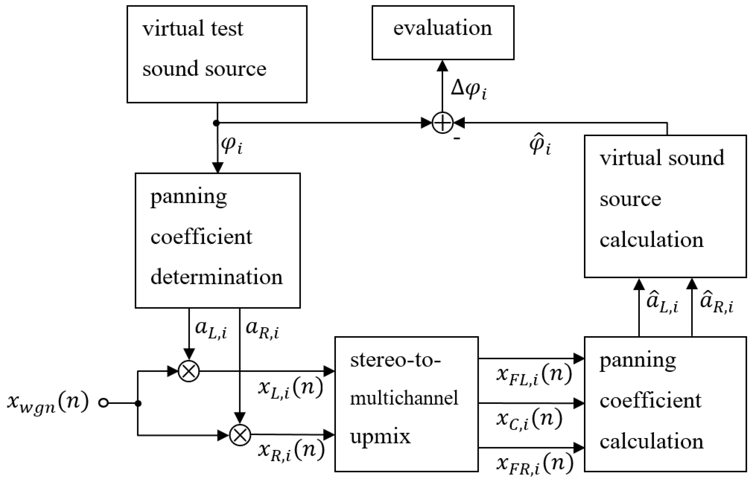
The panning test (see Figure 2) is conducted in two versions. The evaluation score results from the evaluation scores of the time- and frequency-independent panning test and the time- and frequency-dependent panning test , weighted with and , given by
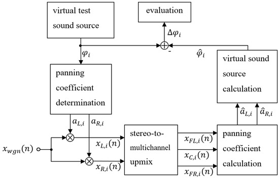
Figure 2.
Block diagram: Time- and frequency-independent panning test.
Initially, at an interval of 1° virtual test sound sources are defined with angles from −30° to 30° according to the reference loudspeaker arrangement [10]. With the tangent law as the modified stereophonic law of sines, the two panning coefficients and can be calculated from [11]. A signal, weighted with the left panning coefficient , represents the left part of a stereo signal . A signal, weighted with the right panning coefficient , represents the right part of a stereo signal . For every angle a stereo test signal is generated as input signal for the tested upmix. This is done by multiplying the resulting panning coefficients and with white Gaussian noise according to
With the output signals of the upmix algorithm for the three front channels (front left), (center) and (front right), two panning coefficients and are determined, and from these panning coefficients the direction of the virtual sound source is calculated. Note that two-to-five upmix algorithms are tested, but only the three front channels are used for the panning test. The difference , which is the deviation of the angle of the virtual sound source of the upmix from the defined test signal, serves as the basis for evaluation. The score of the time- and frequency-independent panning test is calculated from the mean of the normalized absolute deviation of all test cases with and given by
The division by is needed to normalize the mean of the deviations so that the evaluation score assumes values ranging from 0 to 1.
In the case of the time- and frequency-dependent panning test, the angle of the virtual test sound source is randomly generated in the range of −30° to 30°. This is done at any time and frequency in a time–frequency representation with the help of a short-time Fourier transform (STFT). So, the ability of the upmix to respond to fast changes of the virtual sound source should be tested. The score is calculated from the mean of the normalized absolute deviation across all times and frequencies with as the maximum absolute value of all angles given by
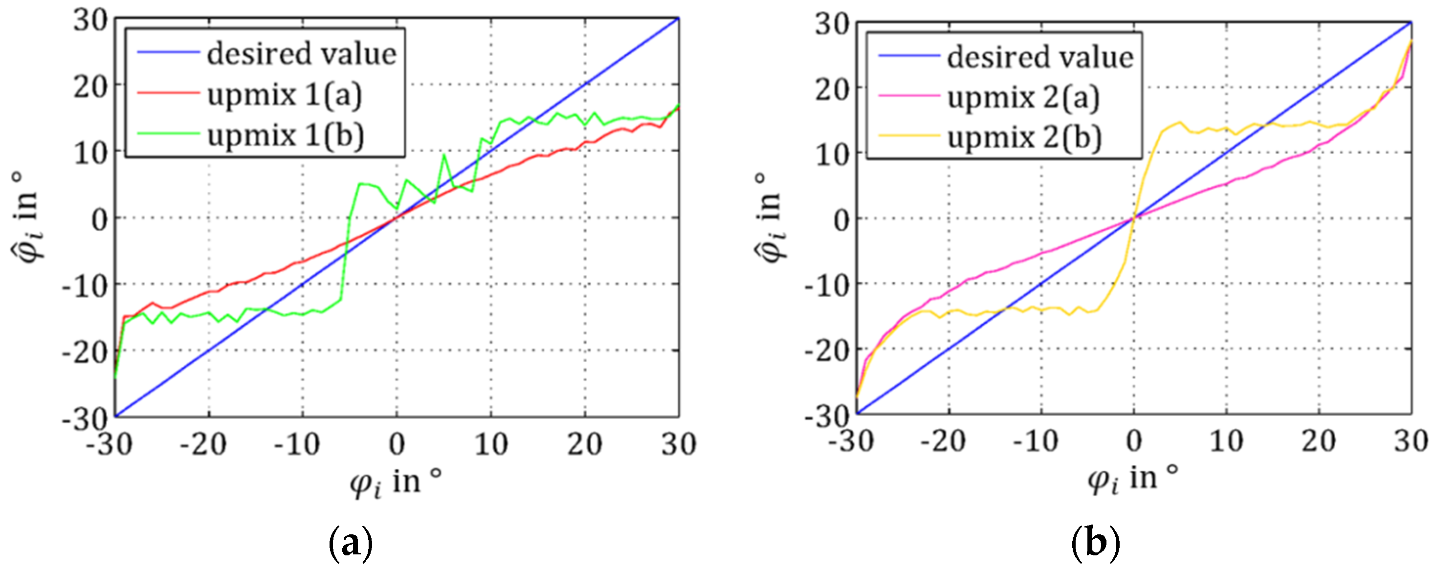
The evaluation allows the comparison of the angle of the virtual sound source of the stereo input signal with the angle of the virtual sound source of the multichannel output signal (see Figure 3).
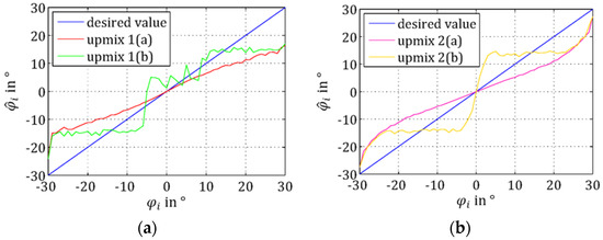
Figure 3.
Panning test—angle of the virtual test sound sources compared with the determined virtual sound sources of the upmix algorithms: (a) algorithms upmix 1(a) and 1(b); (b) algorithms upmix 2(a) and 2(b).
Upmix 1: The more the angle of the virtual sound source in the stereo configuration diverges from in mode (a), the larger are the discrepancies in the multichannel configuration. As a consequence, the spatial extent of the initial stereo configuration is partly reduced significantly. At the same time, the majority of sound events is perceived from a small spot around the center. In mode (b) the direction of the virtual sound source in the multichannel configuration does not even tendentially comply with the direction of the virtual sound source in the stereo configuration. That is because of the aim of mode (b) to enhance speech intelligibility. So, only a small range around the center speaker () is emphasized and parts straight beyond this area are already located considerably further away.
Upmix 2: In mode (a) the angle of the virtual sound source in the multichannel configuration complies tendentially with the angle of the virtual sound source in the stereo configuration. The more diverges from , the larger are the discrepancies in the multichannel configuration until the angle converges fast towards the angle . The spatial extent admittedly nearly remains, but the majority of the virtual sound sources is located closer to the center speaker. In mode (b) the spatial extent admittedly nearly remains, but within a certain area beyond the center () all sound events are solely located in one direction. To enhance speech intelligibility, sound events in the center are emphasized because parts straight beyond this area are located considerably further away.
2.2. Direct Signal Test
Criterion: The remaining amount of direct signal in the surround channels of the stereo-to-multichannel upmix could result in undesired virtual sound sources, which could interfere with the spatial representation of sound events true to original. Although it could lead to a higher subjective perceived spatial quality, the remaining amount of direct signal in the surround channels would be against the assumptions made for upmix algorithms, and should therefore be as low as possible.
Again, a special test signal is defined and used as input signal for the tested upmix algorithm. Different direct signals were taken from the database MedleyDB [12]. These audio recordings were then convolved with room impulse responses and mixed to a test signal (see Appendix A). The procedure of the direct signal test is shown in Figure 4.

Figure 4.
Block diagram: Direct signal test. Note that this is a simplified illustration of room impulse responses as a summary. See Appendix A for details of used room impulse responses and the calculation of and . STFT: short-time Fourier transform.
The generated surround channels (surround left) and (surround right) of the upmix are analyzed by determining their remaining amount of direct signal . This is compared with the known test signal and serves as the basis for evaluation. The score of the direct signal test
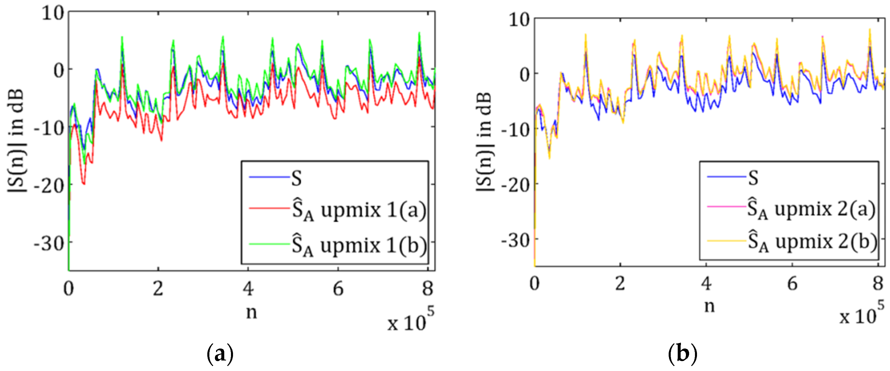
is calculated from the mean of the quotient of the spectral envelopes [13] and of the amounts of direct signals, across all times and frequencies, representing their relative deviation. To ensure a comparative evaluation, the summed power of the extracted surround channels must be equivalent to the summed power of the input signals. That is because signals before and after the upmixing process are considered. Only through using normalized surround signals is a comparative evaluation possible. This ensures, among others, that surround signals are considered correctly, which are identically equal to the input signals but reduced in power. That is because they would have the same relative amount of direct signal. The evaluation allows the comparison of the remaining surround channel direct signal with the known direct signal of the used test signal (see Figure 5).
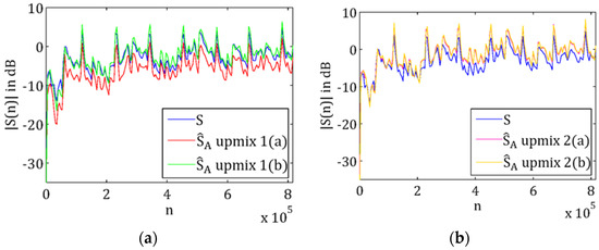
Figure 5.
Direct signal test—remaining surround channel direct signal: (a) Algorithms upmix 1(a) and 1(b); (b) algorithms upmix 2(a) and 2(b). Note that the index in the plots represents discrete values of time. represents the magnitude of the respective complex direct signal averaged over all frequencies.
Upmix 1: Mode (a) contains a reduced remaining direct signal in the surround channels. Mode (b) contains a remaining direct signal which is slightly lower or greater.
Upmix 2: The remaining direct signals are almost identical in modes (a) and (b), but slightly increased relative to the direct signal of the test signal. These proportionally increased remaining surround channel direct signals can occur because of input signal level adjustment or positive feedback of the upmix output signals. It should be noted that other upmix algorithms could also exhibit obviously reduced remaining surround channel direct signals.
2.3. Volume Test
Criterion: Power and loudness of the surround channels of the stereo-to-multichannel upmix should not be greater than the ones of the front channels. No unnatural or unexpected spatial sound should occur because the volume of the surround sound lateral or behind the listener is perceived louder than the volume of the sound events in front of the listener.
The volume test is therefore subdivided into the power test and the loudness test. The evaluation score of the volume test results from the evaluation scores of the power test and the loudness test , weighted with and , and leads to
In each case, five-second-long extracts were taken from twelve popular pieces of music from various genres to create a sixty-second-long test signal (see Appendix B, Table A3).
2.3.1. Power Test
The procedure of the power test is shown in Figure 6.

Figure 6.
Block diagram: Power test.
The defined stereo test signal is used as input signal for the tested upmix. The power , , , and of the generated upmix output signals , , , and are considered. The maximum power of the three front signals is compared with the power of both surround signals and each. The ratios and serve as the basis for evaluation. The evaluation scores of the left and right surround signal, and , are calculated from the means of the quotients across all and times in which the power of the particular surround signals is greater than the power of the front channels, with :
The evaluation scores and represent the relative deviations of the considered power respectively from the maximum power of the three front signals . The evaluation score of the power test results from the evaluation scores of the power test for the left and right surround signal, and , weighted with and , and is given by
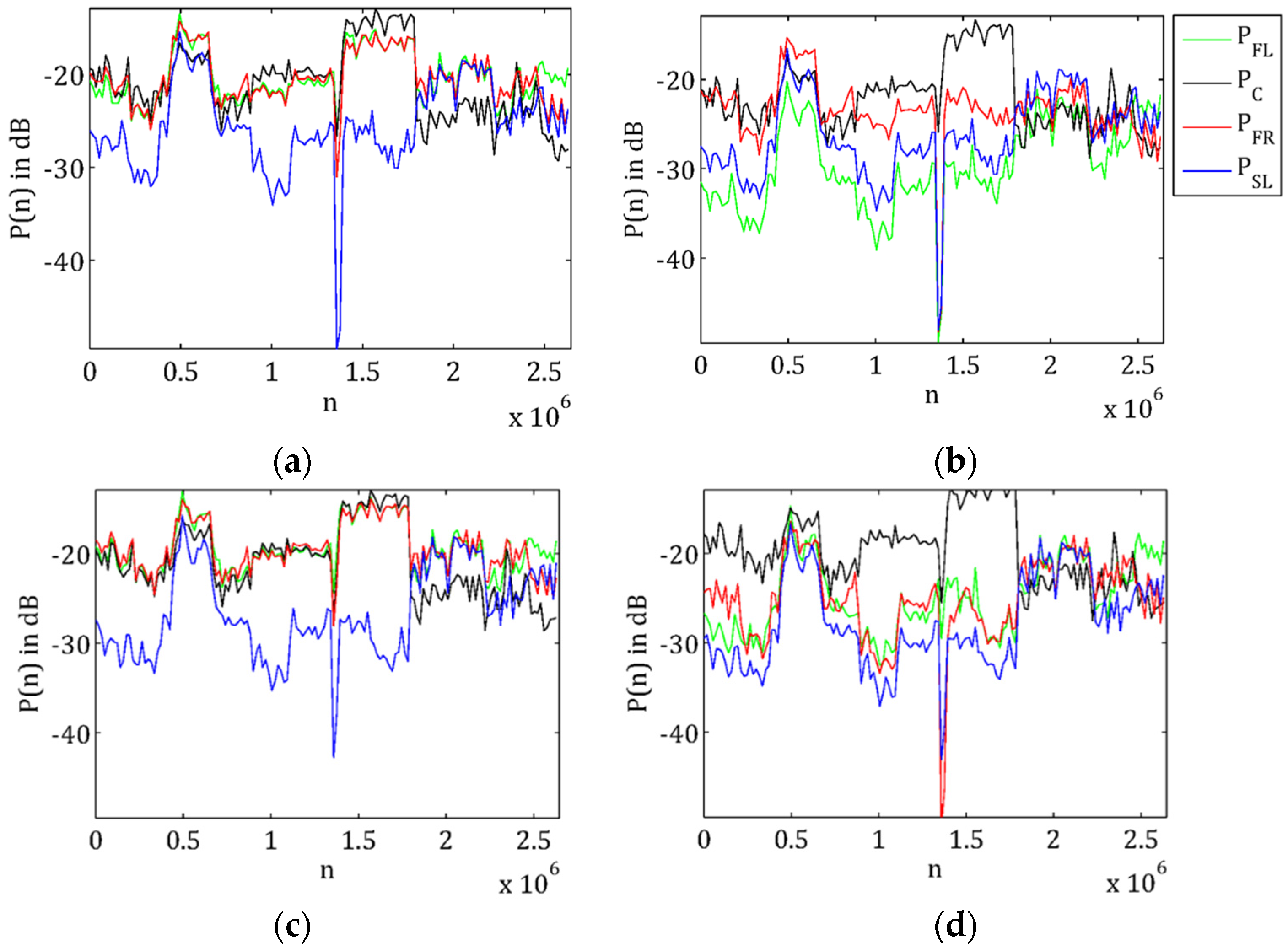
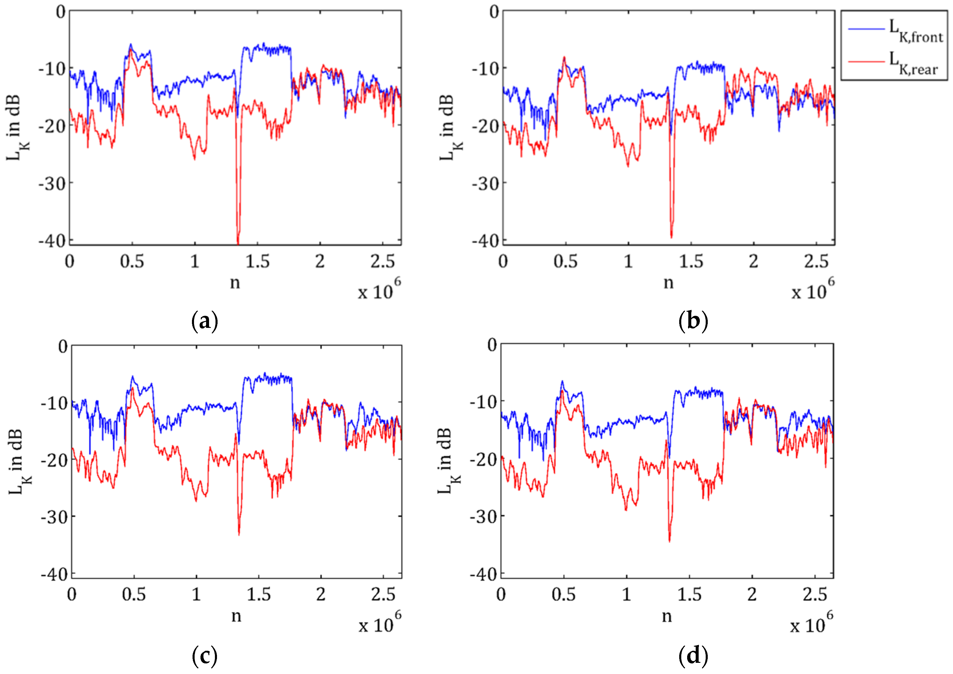
The evaluation allows the comparison of front with surround channel power (see Figure 7). For reasons of clarity only the left surround channel power is used in the following figures.
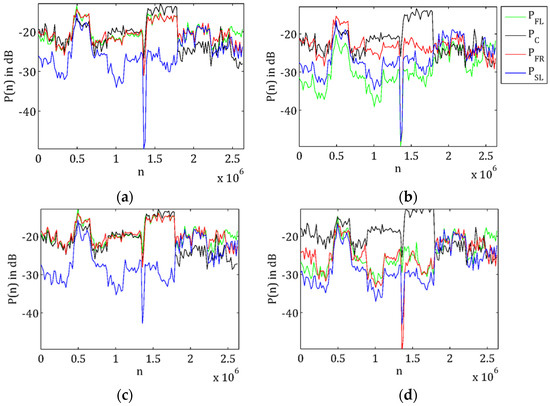
Figure 7.
Power test: (a) Upmix 1(a); (b) upmix 1(b); (c) upmix 2(a); (d) upmix 2(b).
Upmix 1: In mode (a), the power of the left surround channel is basically lower and in some areas partly as high as the power of the front channel with the greatest power. In mode (b), the power of the left surround channel is mostly lower and in some areas partly higher than the power of the front channel with the greatest power. While in mode (a), the power of each front channel is more or less relatively similar, they are mostly considerably different in mode (b). The strong emphasis on the center channel can especially be recognized.
Upmix 2: In mode (a), the power of the left surround channel is basically lower and in some areas partly as high as the power of the front channel with the greatest power. In mode (b), the power of the left surround channel is lower and in some areas partly as high as or slightly higher than the power of the front channel with the greatest power. While in mode (a), the power of each front channel is more or less relatively similar, they are mostly considerably different in mode (b). The strong emphasis on the center channel can especially be recognized.
2.3.2. Loudness Test
The procedure of the loudness test is shown in Figure 8.

Figure 8.
Block diagram: Loudness test.
The defined stereo test signal is used as input signal for the tested upmix. The generated upmix output signals , , , and are considered. The loudness of the three front channels , and is compared with the loudness of both surround channels and . This serves as the basis for the evaluation score of the loudness test . The determination of the loudness is done blockwise according to [14], but separately for the loudness of the front channels and the loudness of the surround channels . The evaluation score is calculated from the mean of the absolute deviations across all blocks in which the loudness of the surround channels is greater than the loudness of the front channels, and is given by
The evaluation allows the comparison of the loudness of the front channels with the loudness of the surround channels (see Figure 9).
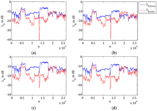
Figure 9.
Loudness test: (a) Upmix 1(a); (b) upmix 1(b); (c) upmix 2(a); (d) upmix 2(b).
Upmix 1: In mode (a), the loudness of the surround channels is basically lower and in some areas partly similar or slightly greater than the loudness of the front channels. In mode (b), the loudness of the surround channels is basically lower and in some areas partly higher than the loudness of the front channels.
Upmix 2: In mode (a) as well as in mode (b), the loudness of the surround channels is basically lower and in some areas partly similar or slightly greater than the loudness of the front channels.
2.4. Phase Test
Criterion: The surround channels of the stereo-to-multichannel upmix should have a certain correlation to prevent uncomfortable perception. If the surround channels would be completely correlated, a mono sound source would be created, which could be perceived as uncomfortable. If the surround channels would be completely decorrelated, two independent sound sources would be created, which could be perceived as uncomfortable, too [15,16,17,18].
The procedure of the phase test is shown in Figure 10. The test signal is identically equal to the test signal of the volume test and is used as input signal for the tested upmix.

Figure 10.
Block diagram: Phase test. Correlation degree is calculated in the block “KOR”.
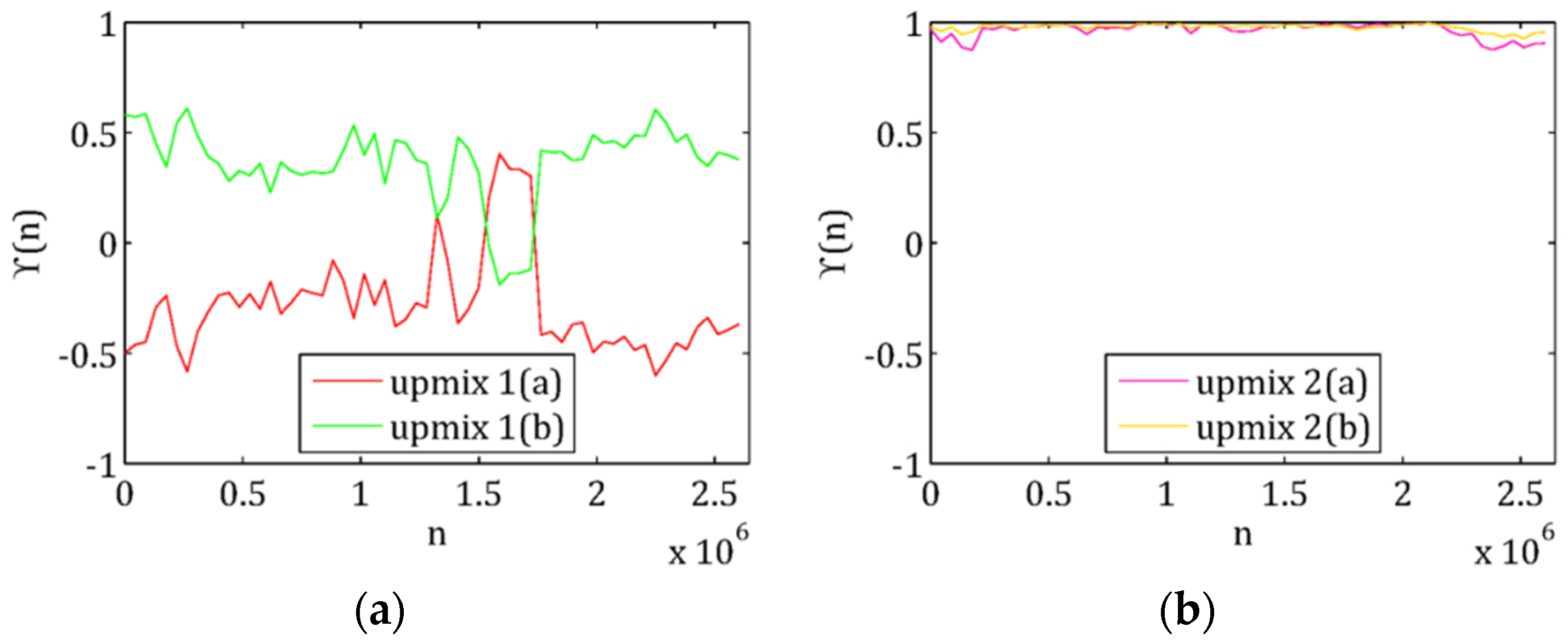
The correlation degree results from the normalized cross-correlation of the generated upmix output signals and for , and leads with
to the evaluation score of the phase test according to
With the requirement that the surround channels and should not be either completely correlated or completely decorrelated, two evaluation limits, and , were defined within which a certain correlation is supposed to be optimal. The tendency for complete correlation and thus the creation of a mono sound source is higher weighted in the evaluation score than the tendency for complete decorrelation. The evaluation allows the comparison of the correlation degrees of the surround channels (see Figure 11).
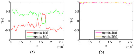
Figure 11.
Correlation degree of surround channels: (a) Upmix 1(a) and 1(b); (b) upmix 2(a) and 2(b).
Upmix 1: In mode (a), the correlation degree of the surround channels is basically negative, in mode (b), basically positive. It is notable that the surround signals of the one mode are a phase-inverted version of the surround signals of the other mode.
Upmix 2: In both modes, the correlation degree of the surround channels is basically approximately one. So, there is the danger that the correlated surround signals are decomposed into a mono signal.
2.5. Perception Test
Criterion: The stereo-to-multichannel upmix should generate a high subjectively perceived spatial quality. This is accompanied with the result that the listening experience is improved compared to the initial stereo configuration, and that the listener feels projected in the middle of the sound events.
The procedure of the perception test is shown in Figure 12. The test signal is identically equal to the test signal of the volume and phase test and is used as input signal for the tested upmix.

Figure 12.
Block diagram: Perception test. IACC: interaural cross-correlation coefficient; LF; lateral energy fraction; LP: low-pass.
The interaural cross-correlation coefficient (IACC) describes the subjectively perceived spatial quality of sound events, and is a measure for apparent source width (ASW). The lateral energy fraction (LF) describes the impression of spatial quality, and is also a measure for listener envelopment (LEV) [7,19,20]. For the determination of IACC, the generated upmix output signals , , , and are used to create a simulated sound field on the basis of head-related impulse responses (HRIR). The binaural signals:
result from the summed generated upmix output signals across all channels of the multichannel configuration convolved with the particular head-related impulse responses and for the left and right ear (with and ).
IACC results from the normalized cross-correlation of the half-wave rectified and with a third-order Butterworth filter () low-pass filtered binaural signals and . The prefiltering ensures that the results correspond better to the subjectively perceived spatial quality [21,22,23].
For the determination of LF, the generated upmix output signals , , , and are used to create another simulated sound field. The signal , which is recorded from a virtual omnidirectional microphone, results from the summed generated upmix output signals across all channels of the multichannel configuration, and is given by
The signal , which is recorded by a virtual bidirectional microphone, results from the summed generated upmix output signals across all channels of the multichannel configuration weighted with the respective loudspeaker directions , and can be written as
LF results, with the signals and , from the ratio of acoustic waves, which are arriving at the listening position laterally and from all directions [7,23], given by
Due to using a simulated sound field, the differentiation between early-and late-arriving signal components is omitted [7].
The evaluation score of the perception test based on IACC results in
and is a direct measure for ASW. The subjectively perceived spatial quality is the higher, the lower IACC is. The evaluation score of the perception test based on LF results in
and is a direct measure for LEV. The impression of spatial quality is the higher, the higher LF is. The evaluation score of the perception test results from the evaluation scores of the perception test based on IACC and LF, and , weighted with and , given by
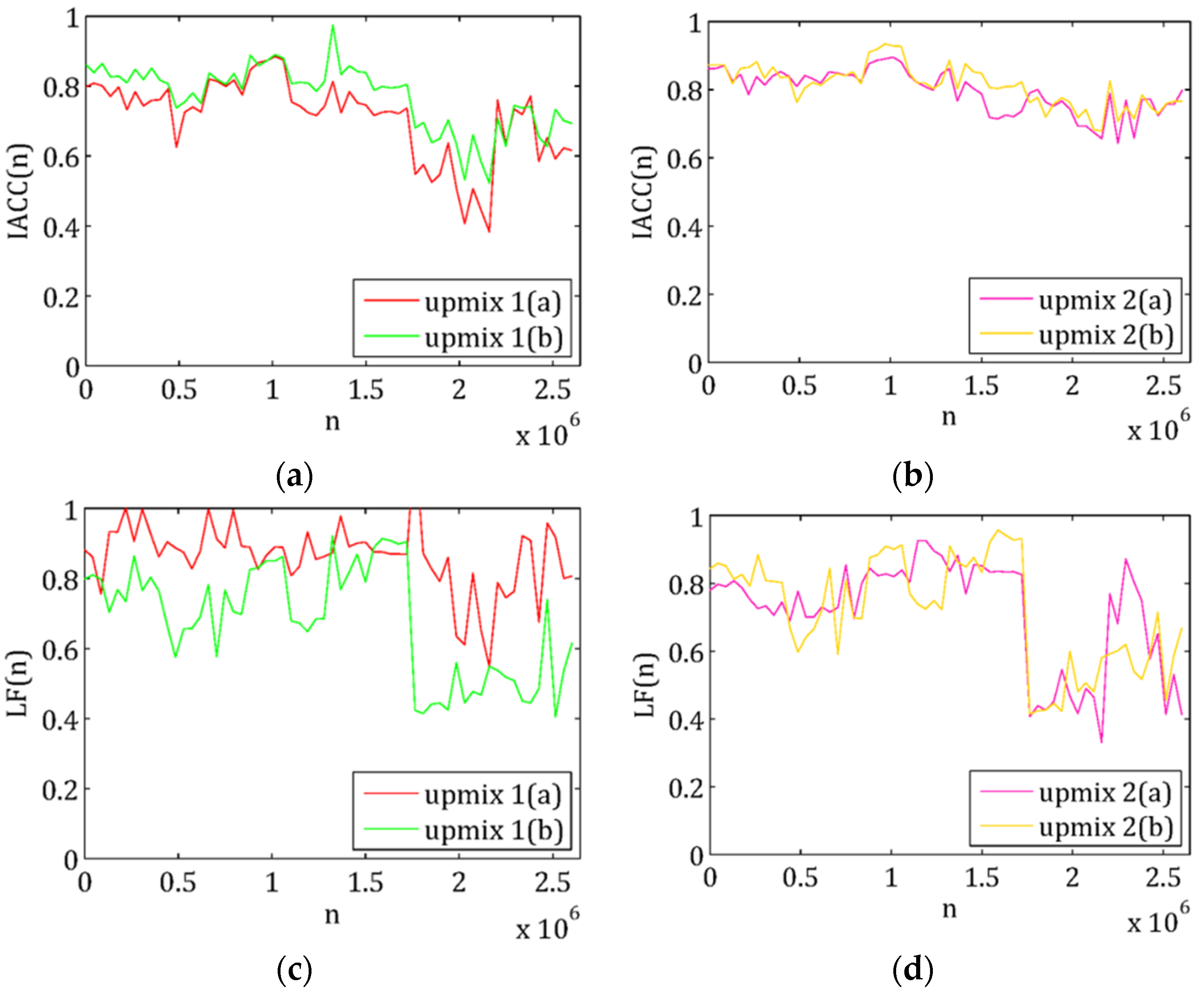
Use of simulated sound fields within the scope of the perception test ensures simplicity because of independence from the properties of room, speakers, microphones, etc., which had to be considered for the determination of IACC and LF based on costly recordings. The evaluation allows the comparison of IACC and LF (see Figure 13).
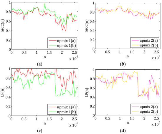
Figure 13.
Perception test: (a) IACC for upmix 1(a) and 1(b); (b) IACC for upmix 2(a) and 2(b); (c) LF for upmix 1(a) and 1(b) IACC; (d) LF for upmix 2(a) and 2(b).
Upmix 1: In mode (a), IACC assumes middle to high values, LF assumes high values (see Figure 13). According to that, middle to low subjectively perceived spatial quality and a high impression of spatial quality occurs. In mode (b), IACC and LF assume middle to high values. According to that, middle to low subjectively perceived spatial quality and middle to high impression of spatial quality occurs.
Upmix 2: In both modes, IACC assumes high and LF middle to high values (see Figure 14). According to that, low subjectively perceived spatial quality and middle to high impression of spatial quality occurs.
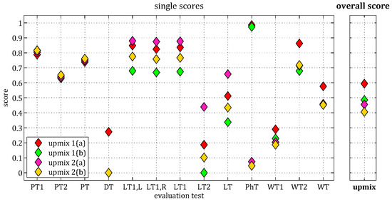
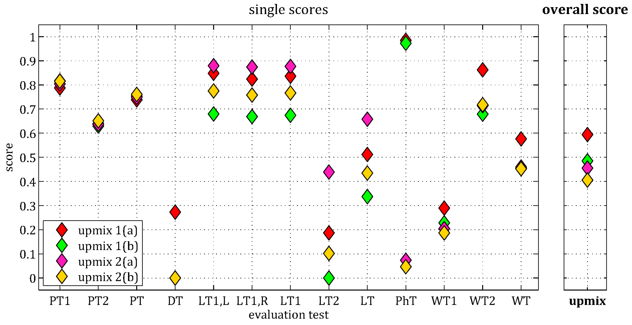
Figure 14.
Evaluation scores of the upmix algorithms—graphical overview.
3. Results
Table A4 (Appendix C) summarizes the single scores of all evaluation tests for the exemplarily tested stereo-to-multichannel upmix algorithms, the used weighting factors and the resulting overall evaluation score. The higher a score, the better the test result of the tested stereo-to-multichannel upmix according to the defined criteria. Zero is the worst, one the best evaluation score. With the help of weighting factors, significance of single tests can be adjusted (see Appendix D). Figure 14 illustrates the evaluation scores according to Table A4. All in all, upmix 1(a) has the best overall evaluation score by far, upmix 1(b) the second best. Upmix 2(b) has the worst overall evaluation score, upmix 2(a) the second worst. Note that two commercial upmix algorithms in two different modes were used to demonstrate the functional principle of the proposed evaluation test and to illustrate how possible results can be visualized. The aim of this paper was not to compare existing upmix algorithms but to introduce an objective evaluation test to gain the possibility of objective comparison. So, an overall evaluation of an upmix algorithm with the proposed evaluation test is appropriate in comparison with other upmix algorithms as references. Therefore, Figure 14 provides an appropriate graphical overview for the comparative evaluation of different upmix algorithms. Note that corresponding results of the single evaluation tests were presented in the end of each section.
For the proposed evaluation test several assumptions about stereo-to-multichannel upmix algorithms were made. Since upmix algorithms are also based on assumptions, the evaluation test will measure how well the assumptions made here were met. Furthermore, a self-contained evaluation of a single upmix algorithm should focus on panning test, direct signal test and volume test. That is because the effects of the correlation of the surround channels (phase test) are perceived subjective. In addition, the impacts of lateral energy fraction and interaural cross-correlation (perception test) on perceived spatiality are subjective, too.
4. Conclusions
In this paper, we proposed an objective evaluation for stereo-to-multichannel upmix algorithms based on defined objective criteria, special test signals and several single evaluation tests. Two upmix algorithms available on the market were used to demonstrate the single tests exemplarily. The panning test checks whether the direction of the virtual sound source in the stereo-to-multichannel upmix corresponds to the direction of the virtual sound source in the initial stereo configuration. The direct signal test checks whether the remaining direct signal in the surround channels is as low as possible. The volume test checks whether the power and the loudness of the surround channels is not greater than these of the front channels. The phase test checks whether the surround channels of the stereo-to-multichannel upmix are not either completely correlated or completely decorrelated, but have a certain correlation. And the perception test checks whether the stereo-to-multichannel upmix generates a high subjectively perceived spatial quality.
The introduced objective evaluation test enables an objective comparative evaluation, which can now provide a measurable quantity for the quality of stereo-to-multichannel upmix algorithms. In addition, the objective evaluation test could be used for the optimization of upmix algorithms and also for the clarification and illustration of the impacts and influences of different modes and parameters. The proposed objective evaluation test is assumed as an appropriate alternative or supplement for time-consuming and expensive subjective listening tests.
Nevertheless, a comparison of the proposed objective evaluation test with subjective test results will be a focus of future work as part of appropriate validation.
Acknowledgments
This research was funded by Helmut Schmidt University, Hamburg, Germany.
Author Contributions
Martin Mieth is the first author, the developer of this research and wrote the paper. Udo Zölzer is the corresponding author, managed the overall research, supervised the complete work and edited the manuscript.
Conflicts of Interest
The authors declare no conflict of interest.
Appendix A
The direct signal used for the direct signal test results (according to Table A1) in
with and . The two-channel test signal results in
The room impulse responses und were taken from the Aachen Impulse Response (AIR) Database [24] with the following parameters:
- type of room impulse response: Binaural; recorded with a dummy head.
- type of room: Stairway.
- distance of sound event to listening position: 3 m.
- angle of sound events: see Table A2.

Table A1.
Used direct signals from MedleyDB.
Table A1.
Used direct signals from MedleyDB.
| Sound Event | File from Database | Variable |
|---|---|---|
| vocals | AClassicEducation_NightOwl_RAW_08_01.wav | |
| bass | AClassicEducation_NightOwl_RAW_01_02.wav | |
| drums | AClassicEducation_NightOwl_RAW_02_01.wav | |
| rattle | AClassicEducation_NightOwl_RAW_11_01.wav | |
| guitar | AClassicEducation_NightOwl_RAW_05_01.wav |

Table A2.
Angle of sound events.
Table A2.
Angle of sound events.
| Sound Event | Angle of Sound Events 1 |
|---|---|
| vocals | 90° |
| bass | 0° |
| drums | 135° |
| rattle | 45° |
| guitar | 180° |
1 Different directions were provided for the single sound events. Here, it is: 0° left, 90° front, 180° right.
Appendix B

Table A3.
Used pieces of music.
Table A3.
Used pieces of music.
| Genre | Interpreter | Title | Time of Title | Time of Test Signal |
|---|---|---|---|---|
| pop | The Human League | Don‘t you want me | 1:18–1:23 | 0:00–0:05 |
| pop | Michael Jackson | Thriller | 1:27–1:32 | 0:05–0:10 |
| pop | Little Talks | Of Monsters and Men | 0:04–0:09 | 0:10–0:15 |
| rock | Metallica | Enter Sandmann | 0:57–1:02 | 0:15–0:20 |
| rock | Motörhead | Ace of Spades | 0:13–0:18 | 0:20–0:25 |
| rock | Black Sabbath | Paranoid | 0:12–0:17 | 0:25–0:30 |
| dance | The Prodigy | Omen | 0:09–0:14 | 0:30–0:35 |
| dance | The Chainsmokers | Selfie | 0:38–0:43 | 0:35–0:40 |
| classic | Antonio Vivaldi | The Four Seasons | 1:10–1:15 | 0:40–0:45 |
| classic | Carl Orff | O Fortuna | 0:08–0:13 | 0:45–0:50 |
| jazz | Louis Armstrong | What a wonderful world | 1:29–1:34 | 0:50–0:55 |
| jazz | Quincy Jones | Pink Panther Theme | 1:48–1:53 | 0:55–1:00 |
Appendix C

Table A4.
Evaluation scores of the upmix algorithms—tabular overview.
Table A4.
Evaluation scores of the upmix algorithms—tabular overview.
| Test Score | Upmix 1(a) | Upmix 1(b) | Upmix 2(a) | Upmix (2b) | Weighting |
|---|---|---|---|---|---|
| 0.7876 | 0.8165 | 0.8045 | 0.8155 | ||
| 0.6393 | 0.6296 | 0.6373 | 0.6510 | ||
| 0.7382 | 0.7542 | 0.7488 | 0.7607 | ||
| 0.2727 | 0 | 0 | 0 | ||
| 0.8484 | 0.6794 | 0.8796 | 0.7751 | ||
| 0.8241 | 0.6686 | 0.8742 | 0.7581 | ||
| 0.8362 | 0.6740 | 0.8769 | 0.7666 | ||
| 0.1866 | 0 | 0.4387 | 0.1019 | ||
| 0.5114 | 0.3370 | 0.6578 | 0.4342 | ||
| 0.9851 | 0.9729 | 0.0737 | 0.0468 | ||
| 0.2894 | 0.2283 | 0.2044 | 0.1867 | ||
| 0.8626 | 0.6788 | 0.7141 | 0.7178 | ||
| 0.5760 | 0.4536 | 0.4593 | 0.4522 | ||
| 0.5938 | 0.4848 | 0.4550 | 0.4055 |
Appendix D
The proposed objective evaluation test uses weighting factors to determine an overall evaluation score from the weighted single-test evaluation scores. With the help of these weighting factors, significance of single tests can be adjusted.
The panning test is conducted in two versions. The aim of the time- and frequency-independent panning test is to test the ability of an upmix algorithm to reproduce the virtual sound sources true to original. Therefore, time- and frequency-independent virtual test sound sources are defined. The aim of the time- and frequency-dependent panning test is to test the ability of the upmix algorithm to respond to fast changes of the virtual sound source. Therefore, time- and frequency-dependent virtual test sound sources are generated independently. Since the focus of the panning test is whether the direction of the virtual sound source in the stereo-to-multichannel upmix corresponds to the direction of the virtual sound source in the initial stereo configuration, the time- and frequency-independent panning test is higher weighted than the time- and frequency-dependent panning test (the time- and frequency-independent panning test counts twice). The evaluation score of the panning test results from the double-weighted time- and frequency-independent panning test () and the single-weighted time- and frequency-dependent panning test (). Due to the assumed high overall importance of the panning test in comparison with the other single tests, the panning test is triple-weighted (). That is because a stereo-to-multichannel upmix should enhance and extend the listening experience without adding artificial effects or contents, and provide virtual sound sources true to original.
The phase test and the perception test are single-weighted (; ) because of the assumed low overall importance in comparison to the other single evaluation tests. That is because the effects of the correlation of the surround channels are perceived subjective. In addition, the impacts of lateral energy fraction and interaural cross-correlation on perceived spatiality are subjective, too. The direct test and the volume test are double-weighted (; ) because of the assumed middle overall importance in comparison to the other single evaluation tests. Thus, they are higher weighted than the phase test and the perception test, but lower weighted than the panning test.
Note that the weighting factors used are not obligatory. They can be used in order to adjust the significance of the single evaluation tests as described above. In addition, they can be used to compare several upmix algorithms with a focus on a special issue.
References
- Avendano, C.; Jot, J.-M. Frequency Domain Techniques for Stereo to Multichannel Upmix. In Proceedings of the 22nd International Conference on Virtual, Synthetic and Entertainment Audio (AES), Espoo, Finland, 15–17 June 2002. [Google Scholar]
- Faller, C. Multiple-Loudspeaker Playback of Stereo-Signals. Jt. Audio Eng. Soc. 2006, 54, 1051–1064. [Google Scholar]
- Goodwin, M.M.; Jot, J.-M. Primary-Ambient Signal Decomposition and Vector-Based Localization for Spatial Audio Coding and Enhancement. In Proceedings of the 2007 IEEE International Conference on Acoustics, Speech and Signal Processing, Honolulu, HI, USA, 16–20 April 2007; pp. 9–12. [Google Scholar]
- Vickers, E. Frequency-Domain Two-to-Three-Channel Upmix for Center Channel Derivation and Speech Enhancement. In Proceedings of the AES 127th Convention, New York, NY, USA, 9–12 October 2009. [Google Scholar]
- Jeon, S.-W.; Park, Y.-C.; Lee, S.-P.; Youn, D.-H.H. Robust Representation of Spatial Sound in Sterei-to-Multichannel Upmix. In Proceedings of the AES 128th Convention, London, UK, 22–25 May 2010. [Google Scholar]
- Usher, J.S. Subjective Evaluation and Electroacoustic Theoretical Validation of a New Approach to Audio Upmixing. Ph.D. Thesis, McGill University, Montreal, QC, Canada, September 2006. [Google Scholar]
- Choisel, S.; Wickelmaier, F. Relating Auditory Attributes of Multichannel Sound to Preference and to Physical Parameters. In Proceedings of the AES 120th Convention, Paris, France, 20–23 May 2006. [Google Scholar]
- Barry, D.; Kearney, G. Localization Quality Assessment in Source Separation-Based Upmixing Algorithms. In Proceedings of the AES 35th International Conference, London, UK, 11–13 February 2009. [Google Scholar]
- ITU-R BS 1116-0. Methods for the Subjective Assessment of Small Impairments in Audio Systems Including Multichannel Sound Systems; Recommendation ITU-R BS 1116-0; International Telecommunication Union: Geneva, Switzerland, July 1994. [Google Scholar]
- ITU-R BS.775-3. Multichannel Stereophonic Sound System with and without Accompanying Picture; Recommendation ITU-R BS.775-3; International Telecommunication Union: Geneva, Switzerland, August 2012. [Google Scholar]
- Pulkki, V. Virtual sound source positioning using vector base amplitude panning. Jt. Audio Eng. Soc. 1997, 45, 457. [Google Scholar]
- Bittner, R.; Salamon, J.; Tierney, M.; Mauch, M.; Cannam, C.; Bello, J.P. MedleyDB: A Multitrack Dataset for Annotation-Intensive MIR Research. Proceeding of the 15th International Society for Music Information Retrieval Conference, Taipei, Taiwan, 27–31 October 2014. [Google Scholar]
- Röbel, A.; Rodet, X. Efficient Spectral Envelope Estimation and Its application to Pitch Shifting and Envelope Preservation. In Proceedings of the 8th International Conference on Digital Audio Effects (DAFx05), Madrid, Spain, 20–22 September 2005; pp. 30–35. [Google Scholar]
- ITU-R BS.1770-3. Algorithms to Measure Audio Programme Loudness and True-Peak Audio Level; Recommendation ITU-R BS.1770-3; International Telecommunication Union: Geneva, Switzerland, August 2012. [Google Scholar]
- Riekehof-Böhmer, H.; Wittek, H. Prediction of perceived width of stereo microphone setups. In Proceedings of the AES 130th Convention, London, UK, 13–16 May 2011. [Google Scholar]
- Theile, G. Multichannel Natural music Recording Based on Psychoacoustic Principles. In Proceedings of the AES 19th International Conference, Schloss Elmau, Germany, 21–24 June 2001. [Google Scholar]
- Damaske, P. Subjektive Untersuchung von Schallfeldern. Acta Acust. 1967, 19, 68. [Google Scholar]
- Usher, J.S. Design Criteria for High Quality Upmixers. In Proceedings of the AES 28th International Conference, Piteå, Sweden, 30 June–2 July 2006. [Google Scholar]
- Hirst, J.M. Spatial Impression in Multichannel Surround Sound Systems. Ph.D. Thesis, University of Salford, Salford, UK, 2006. [Google Scholar]
- Bradley, J.S.; Soulodre, G.A. The influence of late arriving energy on spatial impression. J. Acoust. Soc. Am. 1995, 97, 2590–2597. [Google Scholar] [CrossRef]
- Mason, R.; Brooks, T.; Rumsey, F. Frequency dependency of the relationship between perceived auditory source width and the interaural cross-correlation coefficient for time-invariant stimuli. J. Acoust. Soc. Am. 2005, 117, 1337–1350. [Google Scholar] [CrossRef] [PubMed]
- Neher, T.; Brookes, T.; Mason, R. Musically representative test signals for interaural cross-correlation coefficient measurement. Acta Acoust. 2006, 92, 787–796. [Google Scholar]
- Bradley, J.S. Comparison of concert hall measurements of spatial impression. J. Acoust. Soc. Am. 1994, 96, 3525–3535. [Google Scholar] [CrossRef]
- Jeub, M.; Schäfer, M.; Vary, P. A Binaural Room Impulse Response Database for the Evaluation of Dereverberation Algorithms. In Proceedings of the 2009 16th International Conference on Digital Signal Processing (DSP), Santorini, Greece, 5–7 July 2009. [Google Scholar]
© 2017 by the authors. Licensee MDPI, Basel, Switzerland. This article is an open access article distributed under the terms and conditions of the Creative Commons Attribution (CC BY) license (http://creativecommons.org/licenses/by/4.0/).


