1. Introduction
Additive manufacturing (AM), also known as three dimensional (3D) printing, has been noticeably growing over the last 30 years [
1].
All metal AM technologies are based on the principle of slicing a solid model in multiple layers to create a tool path, uploading these data in the machine, and building the part up, layer by layer, following the sliced model data, using a heat source (laser, electron beam or electric arc) and feed stock (metal powder or wire) [
2]. On the other hand, for large volume the manufacturing speed in AM has not enabled this technology to develop as an economical technique. Thus, the integration of AM processes with the production chain of conventional manufacturing is part of recent research, called hybrid processing [
3,
4,
5]. The most common integration is AM by a deposition process together with a subtractive process like milling. In fact, both deposition and milling processes need a 5-axis machine for full 3D processing [
6]. The DMG MORI SEIKI AG is one of the first producers of a hybrid machine which combines the directed energy deposition (DED) and milling process together in a hybrid machine. A ready to use turbine housing with connection ports for the fuel feed was presented as their demonstration part which was built by the hybrid process within 5 h [
3].
DED, which is a manufacturing technique to build metallic and functional components, is a layer by layer AM process. In principle, in contrast to the powder bed fusion (PBF) processes in which a powder bed is selectively melted, DED is carried out by simultaneously feeding of powder or wire and a concentrated energy source [
7]. In this method a melt pool is formed on the surface of the substrate or last deposited layer by using a relatively high powered laser, such as Nd:YAG or CO
2, or other energy sources and at the same time powder is blown through the laser beam and into the melt pool. In particular, each layer is generated track by track by using a user-defined tool path. Thereafter, the process is repeated layer by layer according to a sliced 3D computer aided drawing (CAD) file, building the component. In this process, the delivery of powder can be carried out by using either a single nozzle or multi-nozzle configuration of the deposition head. Different technologies are generally labeled as DED processes [
8], such as Laser Engineering Net Shaping (LENS), which is a common technology of deposition with multi-nozzle, and others are outlined in
Table 1.
Among the AM processes, DED has a unique position because of its potential to fabricate functionally graded and pure metal components as well as its potential for repairing and cladding of valuable parts that cannot be repaired by other traditional methods. This great potential of fabrication of net shape components and repairing of valuable parts have broadened the applications of DED in the aerospace, medical, and defense industries. Some common materials which have been processed by this technique are listed in
Table 2.
Apart from the aforementioned advantages of the DED process, in-situ alloying, like the other AM processes, can be obtained by feeding the different powders at the same time into the melt pool [
37,
38,
39,
40]. In particular, by adjusting the nozzle feed rate, it is feasible to achieve desirable microstructural features and chemical compositions by alloying in the melt pool of the starting powders [
41]. Furthermore, by changing the process parameters or raw materials during the building process it is also possible to produce functionally graded materials. Moreover, the DED process presents a higher deposition rate and relatively wider process window with respect to the other AM techniques [
42]. Apart from the manufacturing of metallic components, DED is a great tool for repairing high value parts, mainly because of the rather small heat affected zone on the component, very high density, metallurgical bonding, minimal effects such as distortion or cracks in the part, and accurate deposition [
43,
44]. Turbine blades, engine cylinder heads, and blocks are examples of the application of DED as a repairing technique [
45]. Despite all the merits, low powder efficiency and final rough surface are the main disadvantages of this process [
42]. In addition, a large number of studies have shown that the thermal history of a component within the DED has a significant influence on the homogeneity of the microstructure and final mechanical properties of the components [
46,
47,
48].
Ti-6Al-4V is the most commonly used Ti alloy in the aerospace, aircraft, automotive and biomedical industries because of its excellent strength, fracture toughness, low specific gravity, and corrosion resistance [
49,
50]. However, its further exploitation in other applications is challenging owing to its low thermal conductivity and high reactivity features which result in its poor machinability characteristics [
51]. Moreover, due to the heat hardening phenomena during cutting, specific heat treatment operations are generally required. Finally, the high cost of titanium alloys with respect to other competitive materials, highlighted by the comparison of the cost of titanium, aluminum, and steel in the different forms of
Table 3, remarkably affects their widespread use. For these reasons, it is necessary to reduce the cost of fabrication by using economic or near net shape processes: for example, AM technologies have been used to produce net shape components by reducing the cost of fabrication and broadening the applications of this alloy [
52].
The aim of this work is to provide an overview of the additive manufacturing of Ti-6Al-4V alloy by direct laser deposition in terms of microstructural development, mechanical performances, and process optimization. At the beginning, the influence of different factors such as thermal history and process parameters on microstructural evolution within the DED is explained and afterwards, the mechanical characteristics of manufactured components are described. Indeed, the target here is not to assemble all the existing literature about DED of Ti-6Al-4V alloy, but to clarify the importance and opportunities of this innovative process in this field.
2. Microstructure
In general, in a DED process the thermal history of a deposited component has a significant influence on the microstructural features (such as morphology and grain size), in particular due to high heating/cooling rates, significant temperature gradients, and bulk temperature increment. Notwithstanding this, the prediction of the microstructural characteristics of a DED component using the knowledge of many process variables/parameters is still an important challenge [
42,
53]. The best mechanical properties of the final component can be achieved by addressing this main challenge. A large and growing body of literature investigated the correlation between some specific process parameters, microstructure, and mechanical properties of the final components. Although, the relationship between these findings and the fabrication of complicated components with different shapes is not still clear [
54,
55,
56,
57,
58,
59,
60,
61].
Generally speaking, the solidification rate of the melt pool, the ratio between the cooling rate and the gradient of temperature (R), and the thermal gradient at the interface solid–liquid (G) define the microstructure of a deposited part after solidification. Two main critical parameters of solidification can be identified: the ratio G/R affects the shape of the solidification front and cooling rate, whereas the product G × R affects the microstructure dimensions [
42,
53].
Inside DEDed titanium-based components three main microstructures can be observed: in particular, columnar, mix of columnar, and equiaxed and equiaxed microstructures are formed at different G and R values [
47]. It is found that by increasing the ratio G/R the columnar structure is the predominant morphology of grains, while low G/R values promote the equiaxed morphology of grains [
42]. For instance, according to the literature, the appropriate range of G and G × R for the fabrication of thin walls by means of LENS are 100–200 K/mm and 200–6000 K/s, respectively [
62,
63]. However, the optimum values of G and R are strongly affected by several factors such as machine condition, material features, part geometry, and other process parameters. In addition, it is reported that by increasing the solidification rate the microstructure of a component is altered from columnar to equiaxed grains and a cooling rate increment results in a finer microstructure [
42].
Considering the direct laser deposition of titanium alloys, a considerable amount of literature has focused on the attention on production of critical structural parts for aircraft applications, to produce near net shaping components with superior mechanical properties [
64]. Prior beta grain structure is one of the vital structural factors which have a direct effect on the mechanical properties of as-deposited components produced by the layer-by-layer AM process. In recent years, there has been an increasing amount of literature focused on the correlation of the as-deposited grain size and morphology, post heat treatment, and mechanical properties of titanium parts [
65,
66,
67,
68,
69]. It has been found that in the DED of titanium alloys large prior β grains grow epitaxially in the building direction from the parent grains in the melt pool, as a consequence of the rapid solidification due to the high thermal gradient [
13,
27,
58,
70,
71,
72]. This kind of epitaxial growth results in a strong solidification texture and in anisotropic properties. In fact, the tensile ductility and toughness of components in the building direction are higher than the transversal ones [
71,
73,
74]. Previous research has established that epitaxial grain growth and consequently columnar grains is the common mechanism in most of the titanium alloys such as Ti-6Al-4V, Ti-6.5Al-3.5Mo-1.5Zr-0.3Si and so on, and even in titanium aluminides alloys such as Ti-48Al-2Cr-2Nb [
75,
76,
77]. However, in various direct laser deposited parts, different morphologies of prior beta grains were reported in near-alpha, α + β, and near-β titanium alloys. For instance, in laser deposited near-β titanium alloys such as Ti-5Al-5Mo-4V-1Cr-1Fe a “bamboo-like” grain morphology developed in the building direction, including olive-like arrays (coarse short column) and fine equiaxed grains inside the short columns. On the other hand, it was demonstrated that in DED Ti-6.5Al-3.5Mo-1.5Zr-0.3Si by tailoring the parameters it is possible to obtain a mix of columnar and equiaxed grains perpendicular to the building direction [
28,
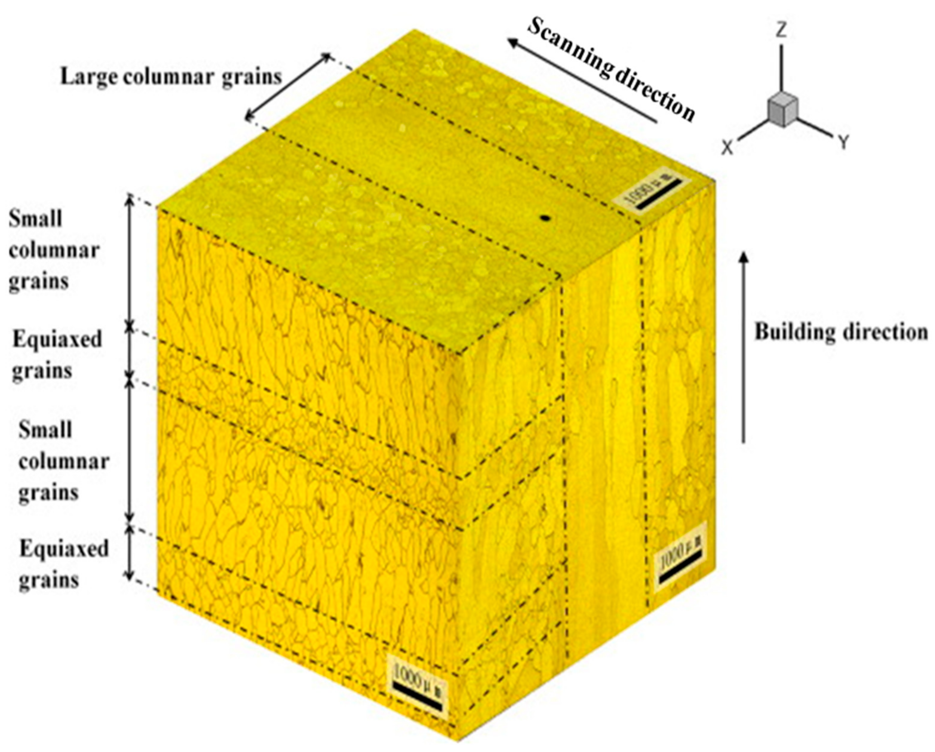
78]. However, it seems there is a lack of experiment and proof to explain the diversity of prior beta grain morphology. Liu et al. observed that the microstructure of layer bands of Ti-5Al-5Mo-4V-1Cr-1Fe near beta titanium alloy produced by direct laser deposition is duplex with low hardness, whereas between the layers the microstructure is ultra-fine basket-weave with very high hardness [
28]. Indeed, they used a 8 kW continuous wave CO
2 laser material system with a four axis Computer Numerical Controlled (CNC) work station and the pre-alloyed powder was fed into the melt pool through a coaxial nozzle. An argon purged processing chamber with oxygen content less than 50 ppm was employed to avoid oxidation. They showed the typical microstructure of beta grain morphology which includes three sorts of grains: large columnar grains, small columnar grains, and equiaxed grains (
Figure 1). The mixture of small columnar and equiaxed grains is defined as “bamboo-like” grain morphology, in which the equiaxed grains are revealed between the small columnar grains in the building direction. This kind of grain morphology evolution during the DED process is in line with the other works [
79,
80,
81]. In this study, it was found that the large columnar and bamboo-like grains are arranged alternatively in the front and top view. It was also shown that at the opposite direction of laser scanning, small columnar grains with a zigzag pattern and 20° orientation with respect to the building direction are grown. This specific orientation is explained by the direction of heat conduction during the direct laser deposition [
28]. It was found that the different processing and post-process conditions were expected to result in various microstructures and a wide range of mechanical properties [
82,
83,
84]. For instance, the microstructure of components produced by laser or electron beam based DED in as deposited condition exhibited a lamellar α + β structure. Despite a similar microstructure in both laser and electron beam DED, the scale of these microstructure characteristics varied depending on the AM process. It was reported that the microstructure of electron beam based DED is coarser with respect to the laser based one [
59,
82].
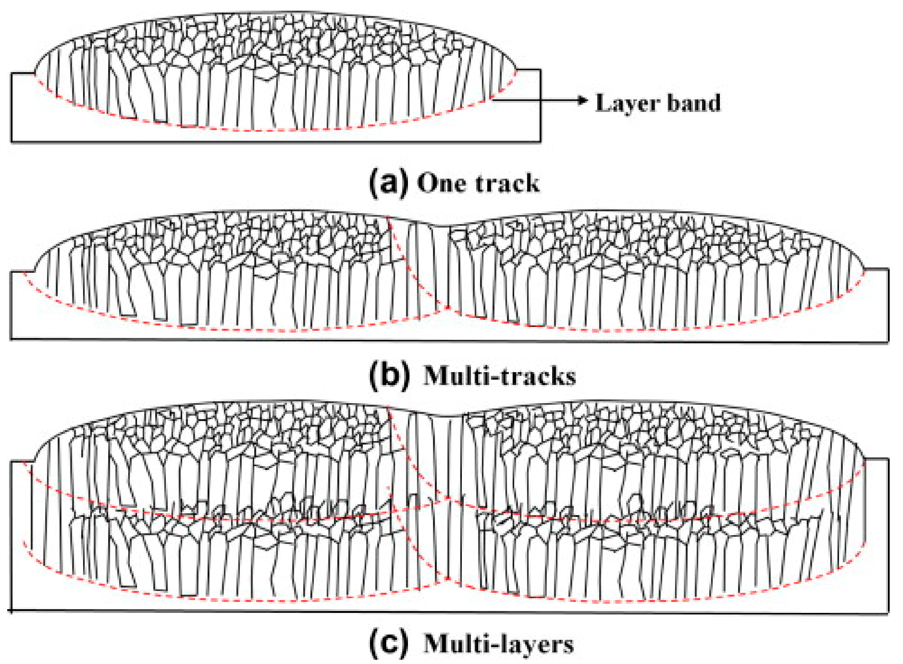
Liu et al. suggested the development of grain morphology during the direct laser deposition of different geometries (
Figure 2). As can be seen in
Figure 2a, when a single scan track is deposited, columnar grains at the bottom of the melt pool are formed as a consequence of high thermal gradient and rapid cooling undergone by the substrate. By increasing the height of the melt pool, the thermal gradient and cooling rate decreased up to the top of the melt pool. These variations in thermal gradient and cooling rate result in the formation of equiaxed grains on top of the melt pool. In the case of multi tracks (
Figure 2b), in the overlapped areas between consecutive scans the equiaxed grains remelt and then solidify in the form of columnar grains. This change in the grain morphology in the overlapped zones was reported as a consequence of the lower depth of melt pool in these regions which results in higher thermal gradient and cooling rate that promote the epitaxial grain growth. Regarding multi layer deposition (
Figure 2c), it was reported that the partially remelted, equiaxed grains act as nuclei for the epitaxial grain growth, resulting in the formation of columnar grain morphology. Thereafter, the grain structure of the new deposited layer becomes similar to the previous layer and this grain structure repeats in every layer up to the last deposited layer. However, it was concluded that the variation of direct laser deposition parameters changes the evolution of grain morphology, thus further investigations about the effect of LMD process parameters on the development of grain morphology are still required.
Figure 3 shows the formation of a fine basket-weave microstructure in the area between the bands and a duplex microstructure including ultra-fine and coarse alpha laths within the layer bands. It was thus concluded that high cooling rates involved in DED result in the formation of ultra-fine alpha laths that are much finer than the Widmanstätten microstructure which forms in the α or α + β alloys [
28,
85].
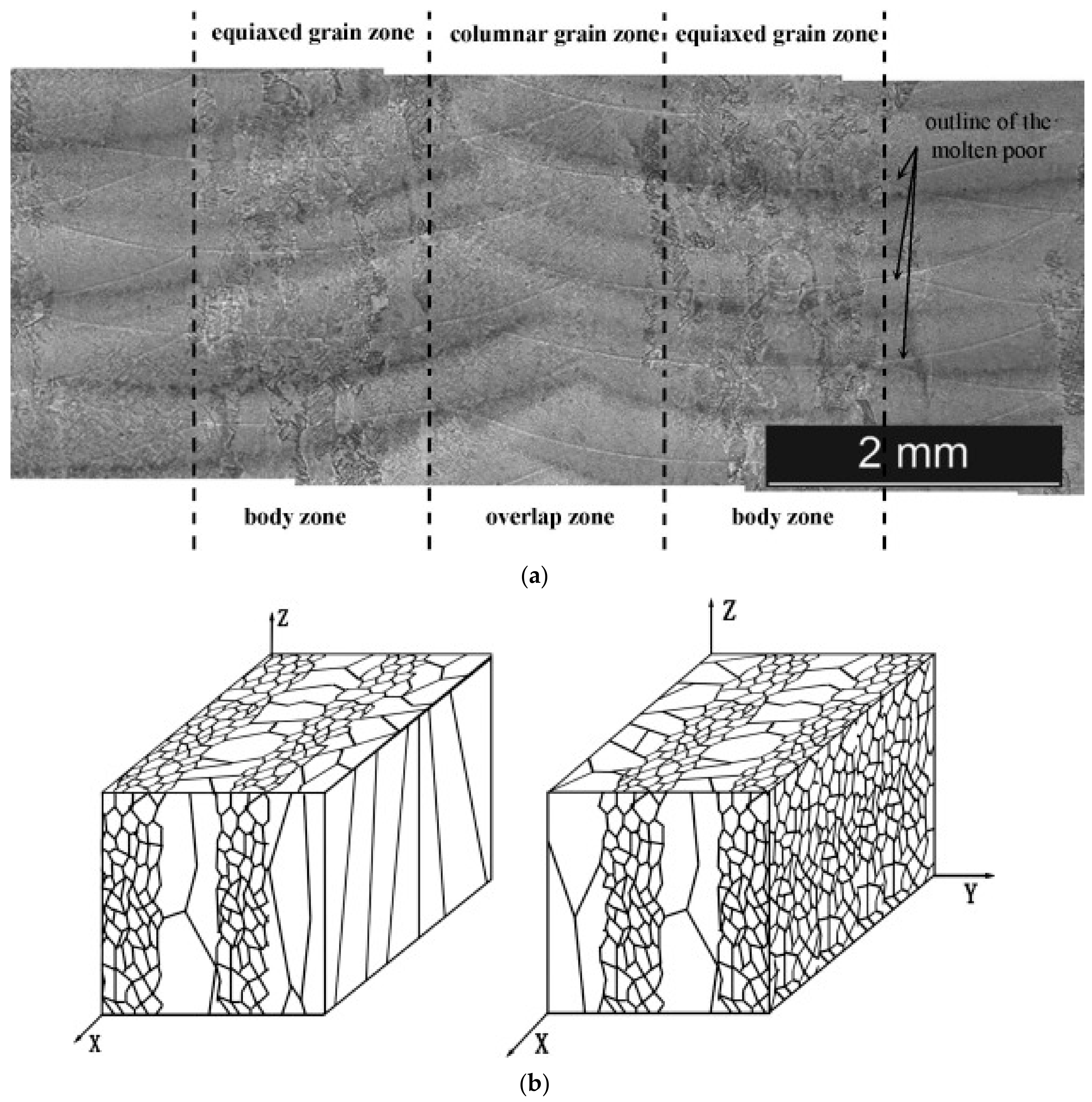
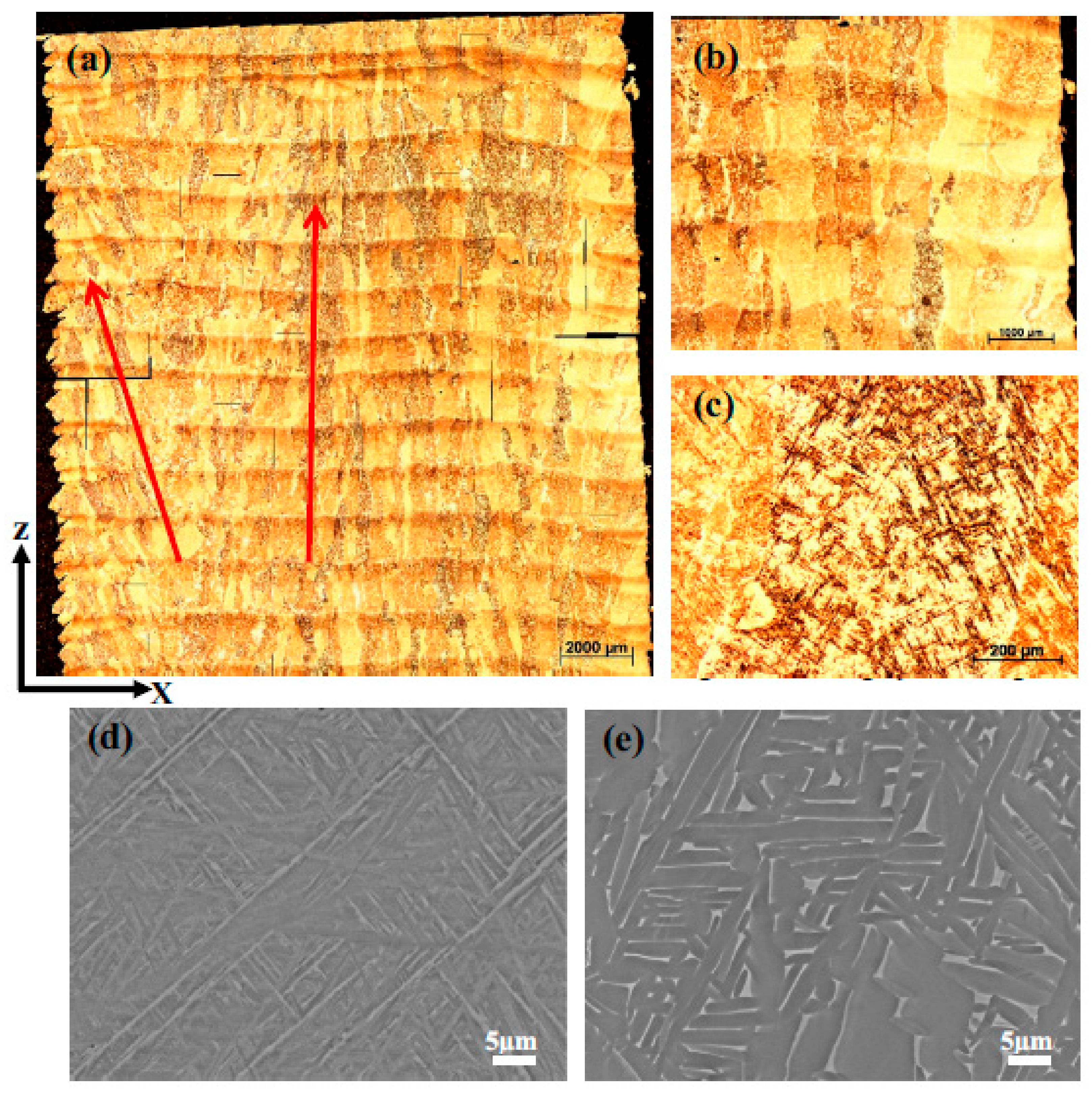
Zhu et al. investigated the microstructure and mechanical properties of laser metal deposited Ti-6.5Al-3.5Mo-1.5Zr-0.3Si, an α + β titanium alloy [
25]. In this work, to fabricate the specimens a 6 kW fiber laser melting deposit manufacturing system with an argon purged processing chamber was used. The oxygen content was kept less than 50 ppm to prevent any oxidation. In this research, laser power 6 kW, laser beam diameter 5 mm, scan speed 800 mm/m, powder feed rate 500 g/h were chosen as optimum parameters and the starting powder was fed by means of a coaxial nozzle. In these materials the columnar grains are presented in the overlapping zones whereas the equiaxed grain structures are located in the body zones. Zho et al. correlated this kind of microstructure with the temperature gradient (G) and solidification rate (V). Indeed, they observed that at high G and low V, columnar grains are predominant, while at low G and high V equiaxed grains form [
86]. Thus, they concluded that the values of G and V at various locations of a melt pool should be different, although the geometry and size of melt pool is dynamically stable while it keeps moving [
25].
They also demonstrated schematically the 3D grain morphology of Ti-6.5Al-3.5Mo-1.5Zr-0.3Si titanium alloys obtained after direct laser deposition (
Figure 4), with a particular microstructure consisting of alternative arrays of columnar and equiaxed grains [
25].
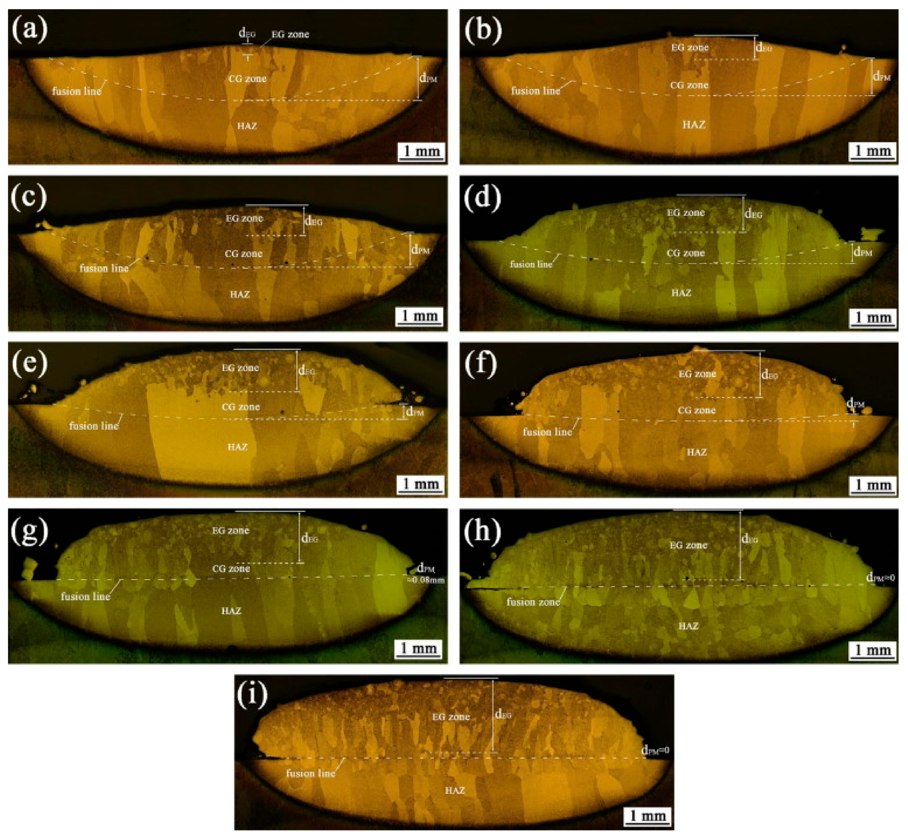
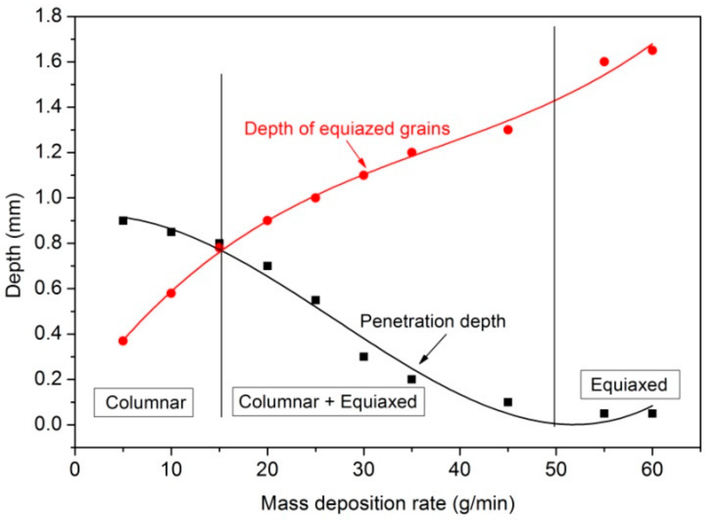
Wang et al. investigated the solidification nucleation and growth mechanisms of the local melt pool over direct laser deposition, evaluating the effect of mass deposition rate (m) on the area fraction of equiaxed and columnar grains [
87]. In this research a 10 kW fiber coupled diode laser with a beam wavelength of 980–1020 nm, a 4-axis mechanical work station, an argon-purged processing chamber, a coaxial powder feeding was employed to fabricate the component. To avoid any possible oxidation the oxygen content was kept less than 80 ppm. It was reported that by increasing the m values the area fraction of equiaxed grains increases whereas the area fraction of columnar grains decreases significantly (
Figure 5). In fact, when the mass deposition rate is increased to a very high value, the mechanism of grain evolution changes: in these conditions the epitaxial growth of parent grains is prevented and new nucleated equiaxed grains cover more than 80% of the whole deposited layer. However, a short distance from the pool fusion line some short-columnar or olive-like morphology can be detected. Moreover, it was stated that by increasing the mass deposition rate the penetration melting depth significantly decreases and after a critical point no penetration melting occurs, making layer by layer additive manufacturing impossible [
87].
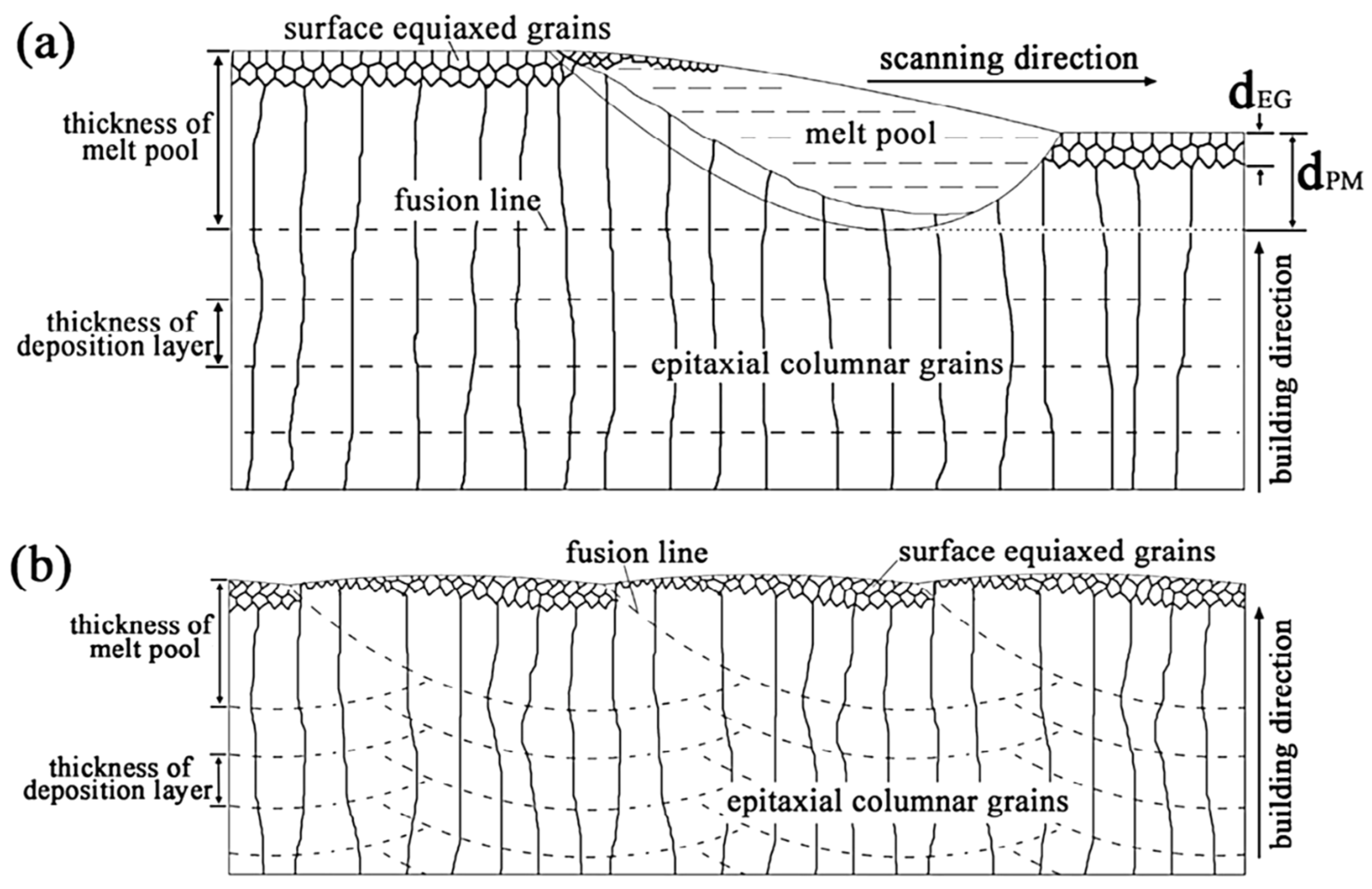
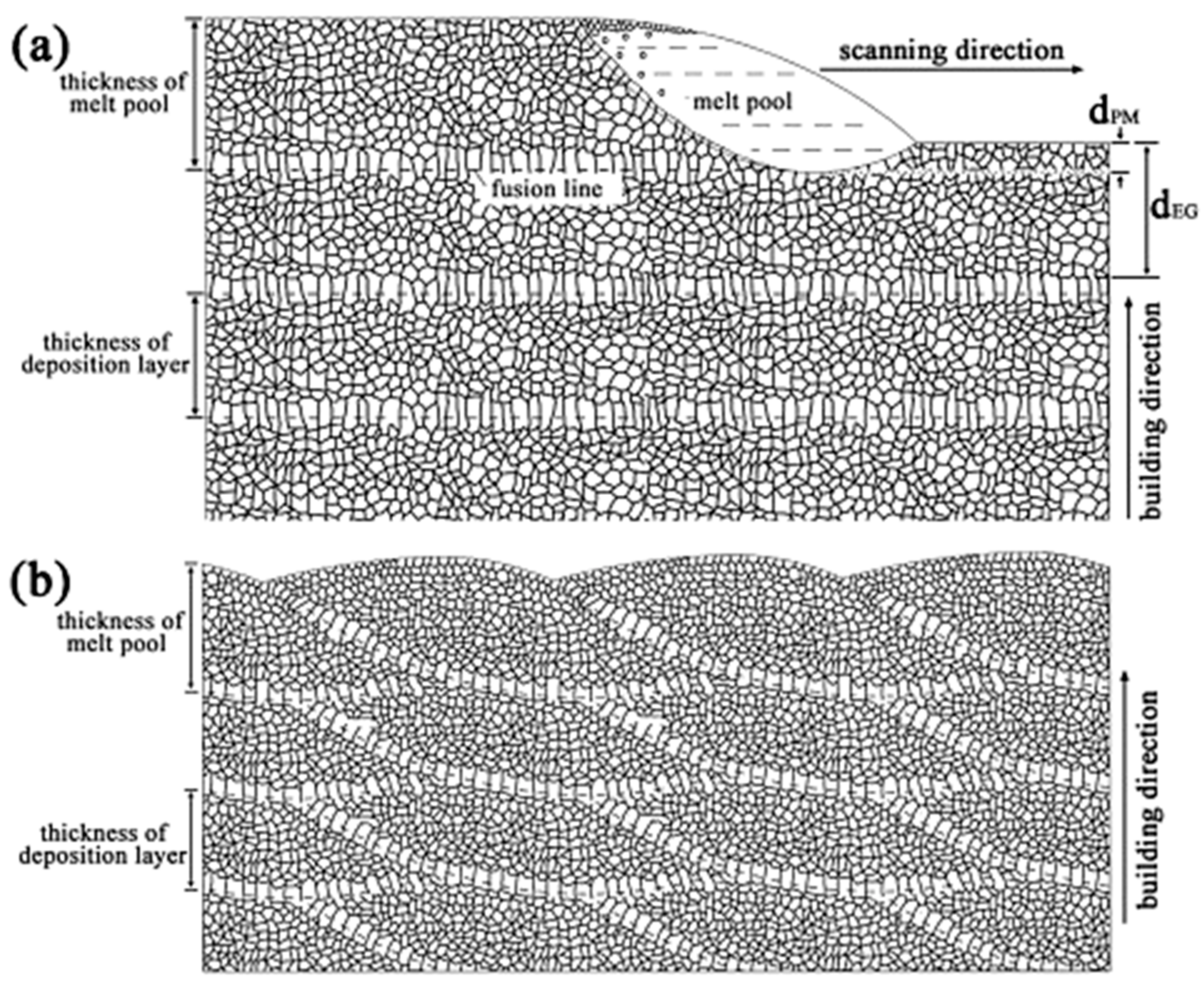
It was found that there is a critical threshold for the “m” values, below which a full columnar grain structure can be achieved (
Figure 6 and
Figure 7). Beyond the upper value of this threshold, the penetration melting depth is lower than mass deposition rate and a fully equiaxed grain structure will be obtained. Indeed, in this region the excessive laser power is very low to melt all the delivered powder, thus these partially melted particles either in the melt pool or on the surface of the melt pool promote a heterogeneous nucleation and growth mechanism that results in the formation of a fully equiaxed grain structure (
Figure 8) [
87].
On the other hand, in titanium materials deposited with the mass deposition rate between the lower and upper values of threshold (m
CL < m < m
CU) a mix of columnar and equiaxed grain structure is achieved. This type of microstructure is formed on the basis of the geometry of the melt pool, in which at the lateral bottom metal grains hardly re-melt during the pool formation of the subsequent layer. This evolution occurs because in this zone, grains start to grow epitaxially owing to the different thermal gradient with respect to the center of the melt pool. In general, the authors concluded that a low specific mass deposition rate results in high melt superheating, large penetration re-melting, and a high thermal gradient, promoting the epitaxial growth. As a consequence, columnar grain structure is observed in the final microstructure. On the other hand, a high specific mass deposition rate implies low melting temperature, insufficient powder melting, and high superficial and endogenous heterogeneous nucleation sites, leading to the formation of a near equiaxed grain structure [
87].
In the case of fabrication of large Ti-6Al-4V structures produced by the DED process, Qiu et al. found that it was feasible to produce a porosity free component by using a combination of high laser power together with a reasonably low powder feed rate [
88]. According to their studies, the height of deposition is correlated to the Z steps: under-build phenomena or excessive building can occur with high or low values, respectively, and columnar grain structure with martensitic needles is observed.
In addition, the authors also evaluated the effect of Hot Isostatic Pressing (HIP) on the microstructures of DED specimens, as presented in
Figure 9. First, it is possible to underline that columnar grains and martensitic are the dominant structure in the as-DED condition. The formation of columnar grains can be explained by the heat dissipation phenomenon during the DED process. In particular, the columnar grains start to grow epitaxially in the middle section in the opposite direction of heat dissipation. On the other hand, in the peripheral areas the grains grow at a slant angle with respect to the building direction owing to the participation of radiation in the heat dissipation. After HIP, the transformation of martensite into lamellar α + β was suggested [
88].
Several studies have shown that in general a different thermal gradient and cooling rate which result in different microstructures have influence on the microhardness of Ti-6Al-4V components [
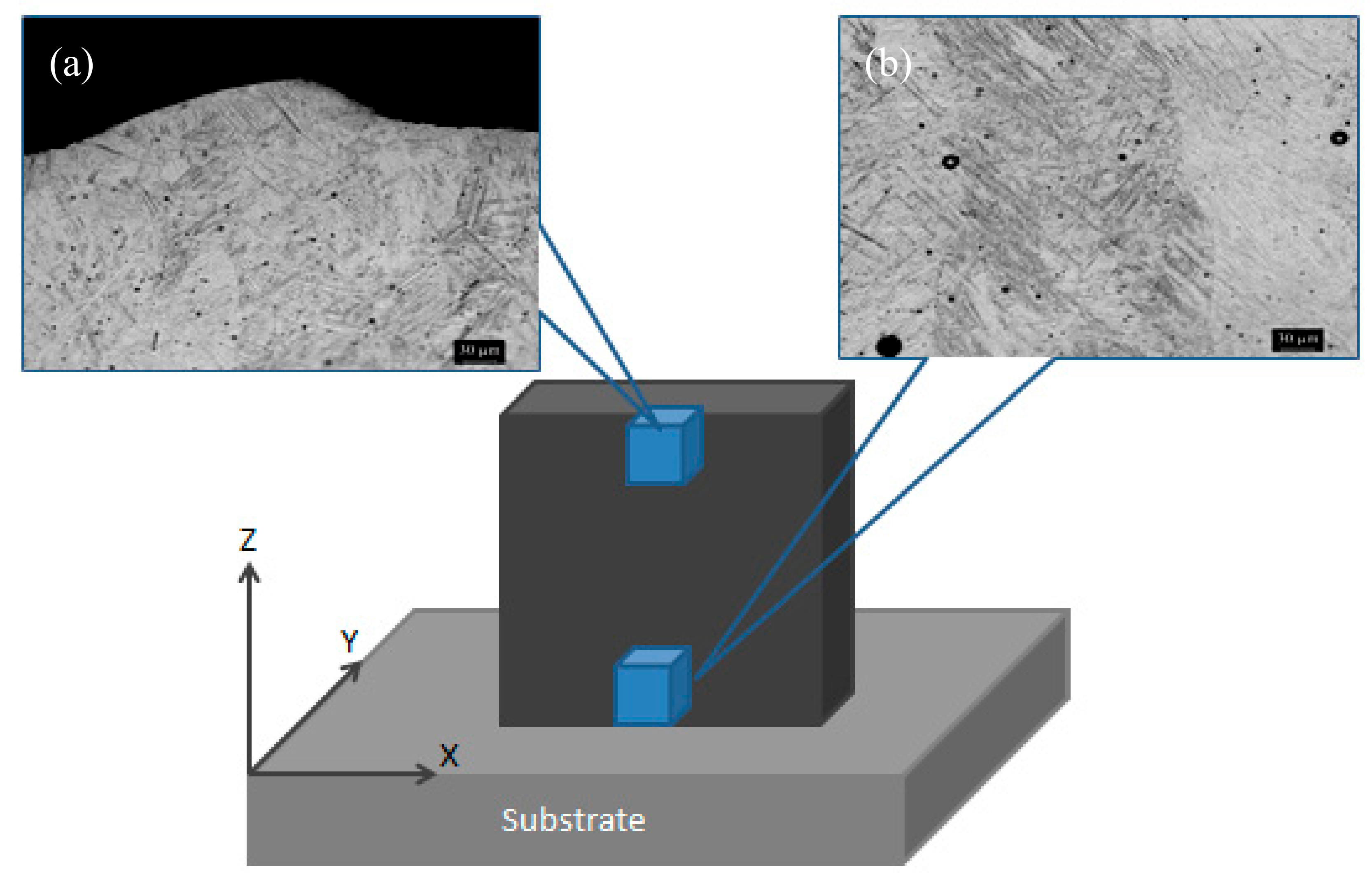
18]. In the case of DEDed Ti-6Al-4V components, as discussed earlier the microstructure of the part in both the top and bottom includes the Widmanstätten structure, although the morphology varies in each area. In fact, at the top of the sample the colonies of parallel, very fine lamellae, and larger laths is revealed whereas in the bottom region the lamellae become thicker (
Figure 10). This discrepancy can be related to the thermal gradients, cooling rates, and cycling thermal treatments during the laser deposition step [
42,
89].
A residual stress is a stress produced in a body in a mechanical and thermal equilibrium condition without external forces [
90]. The main sources of residual stress after DED are the dynamic temperature distribution and cooling/heating rate within the component that contains high thermal gradients and repetitious/rapid local heat transfer rates [
91,
92]. Therefore, it is very important to study the thermal history of a component during the DED process because of its significant effects on the anisotropy of microstructure and level of residual stress inside the part. Another significant effect of tensile residual stress inside the component is on the tensile and fatigue resistance. A reduction of mechanical performance and dimensional inaccuracies are the other consequences of the presence of residual stress after the process.
Thermal conductivity, coefficient of thermal expansion, Young’s modulus, and yield stress together with phase transformation, part geometry, process parameters during fabrication, and scanning pattern all affect the level and type of the residual stress inside the sample [
91,
93].
It was found that materials with higher strain mismatch during the cooling step, high Young’s modulus, and yield stress usually show the formation of higher level of residual stresses [
91].
Several lines of evidence suggest that in Ti-6Al-4V alloy there is a correlation between residual stresses within the building plane and the laser scanning direction in which there is a compressive residual stress at the center and tensile stress at the edges of the component. Moreover, it was reported that at the starting point of laser scanning the level of residual stresses is lower and finally reach their maximum at the end of the laser scanning path [
94]. On the other hand, it was detected that in the first deposited layers the level of compressive stress was very high and by increasing the number of layers this compressive stress transit to tensile residual stress. According to previous works, it would be possible to reduce the residual stresses through the optimization of the process parameters, using an appropriate melt pool size and morphology, employing a proper scan strategy, and preheating of the substrate or last deposited layer [
91,
92,
95,
96,
97,
98].
Laser power, laser scanning speed, powder feeding rate, and scanning strategy are the main important process and design parameters that can affect the thermal history, microstructure and level of residual stresses within the laser deposited component. Indeed, these parameters affect the cooling rate and local temperature gradient by changing the melt pool geometry and incident energy [
42,
47].
A low energy density which is a combination of high scanning speed and low laser power results in a fine microstructure whereas, at low laser scan speed and high laser power (high energy density) a coarse microstructure consisting of columnar grains is the predominant microstructure [
47,
48].
Bontha et al studied the effect of process parameters of DED on the microstructure of thin wall components of Ti-6Al-4V alloy produced by a LENS
TM system. They found that by increasing the energy density the size of DEDed components increased. Moreover, they showed that the effect of powder feeding rates at higher laser powers is less so that at higher powder feeding rates the microstructure turns into a columnar microstructure. On the other hand, by increasing the laser scan speed the size of α and β laths decreases and the level of porosity increases [
48].
Li et al. studied the correlation between the powder feeding rate and powder density in the melt pool. A laser rapid forming system with a 5 kW continuous wave CO
2 laser, a 4-axis numerical working table, and a powder feeder with latheral nozzle were chosen to deposit the components. They showed that the powder feeding rate does not have a serious effect on the distribution of powder density in the melt pool [
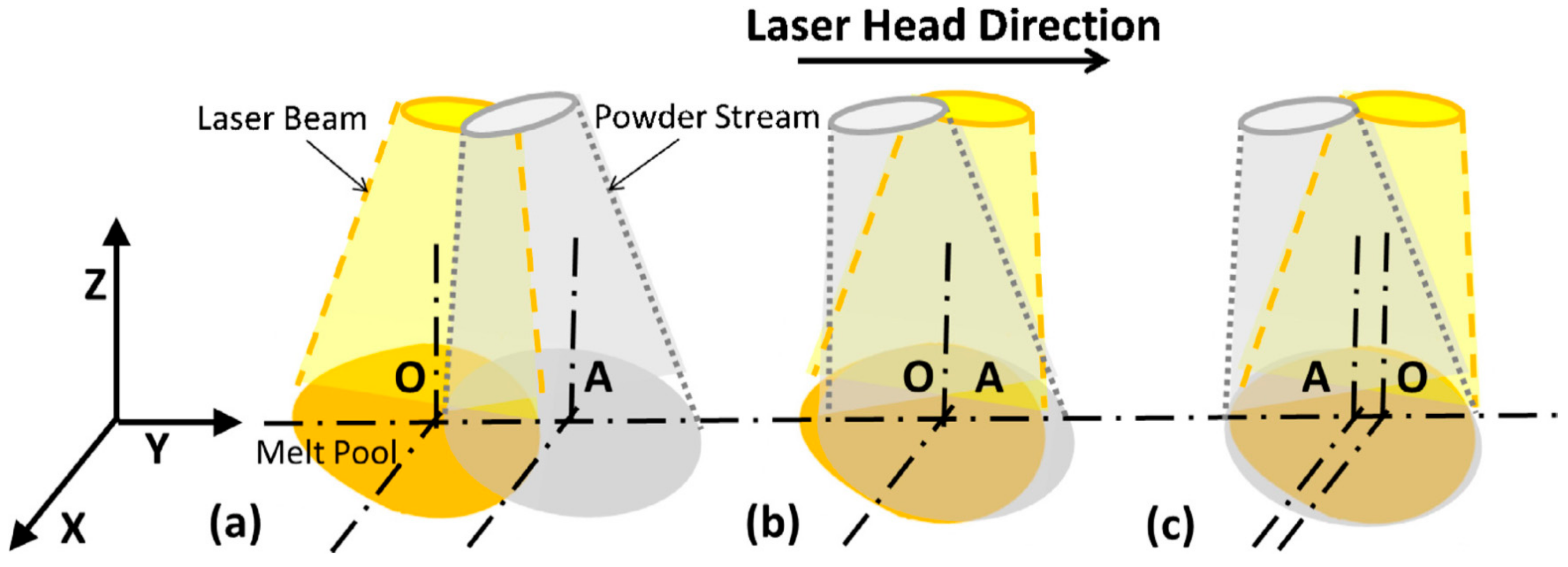
99]. They reported that the layer height increases linearly on increasing the powder feeding rate. For a given powder feeding rate, the amount of powder which is delivered into the melt pool varies in different directions of laser scanning. This discrepancy is likely related to the different distance between the powder feeding stream and the laser spot. By changing the direction of laser scanning the point of powder delivery changes and it can be ahead, in line or behind the laser spot (
Figure 11). This variation will affect the geometry of the melt pool, boundary, and solidification heat transfer and consequently the height of deposition. As can be seen in
Figure 11, when the powder delivery point (A) is in front of laser spot (O) the amount of delivered powder into the melt pool is less while, this amount is slightly higher in the case when the powder stream is behind the laser spot. Thus, in order to have a constant mass flow rate of deposition the powder feeding rate and laser scan speed should be set according to the laser scan direction and the distance between the laser spot and nozzle. The amount of powder that is delivered into the melt pool is also varied according to the flow rate of the shielding gas so that by increasing the gas flow rate the layer height increases significantly. The high flow rate of shielding gas results in a higher level of porosity and also higher spreading out of the particles and thus affects adversely the deposition.
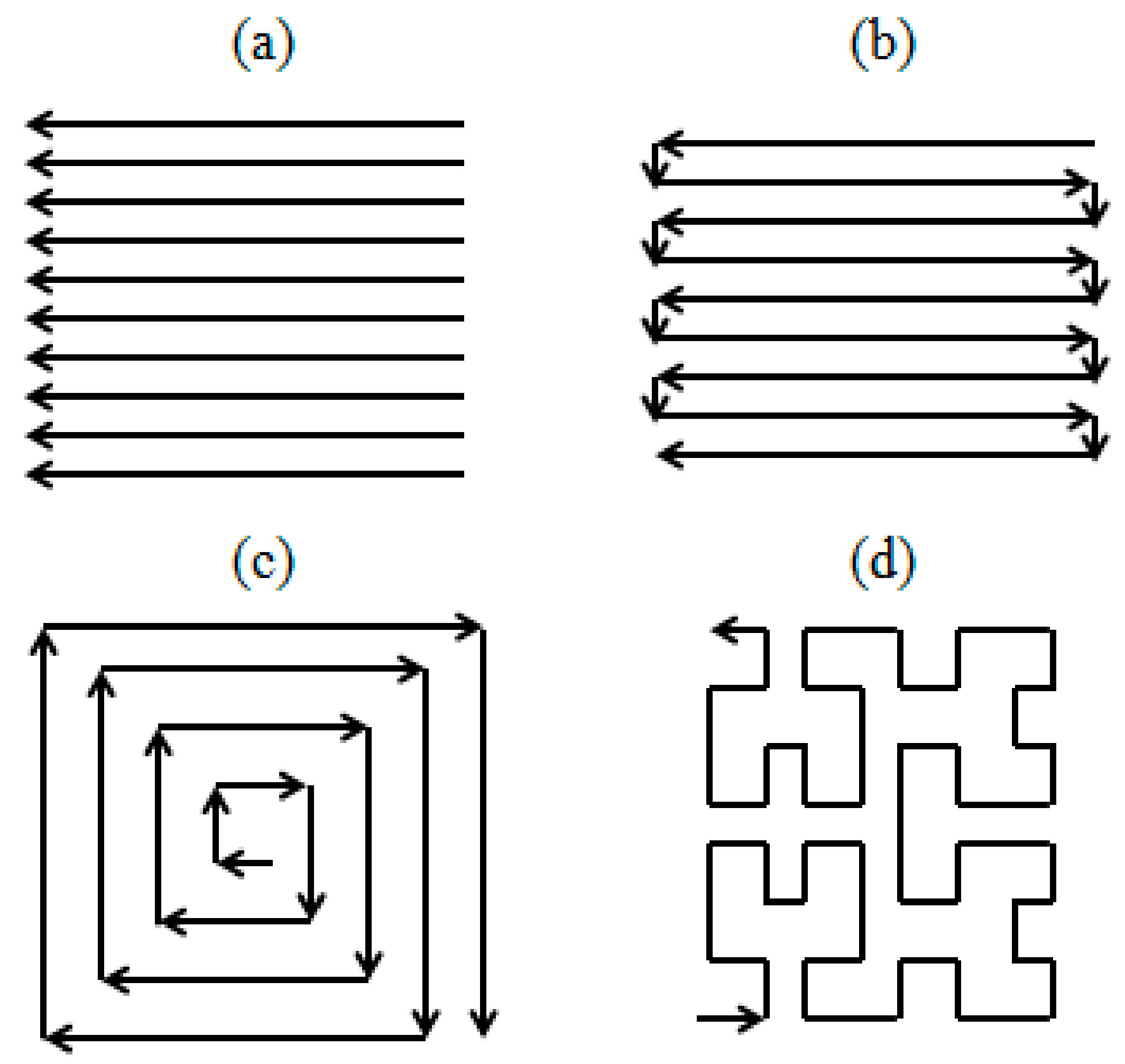
Generally speaking, raster, bi-directional, offset and fractal patterns are the main four deposition strategies (
Figure 12) [
100]. In addition to these scan strategies, some sub-strategies can be used to deposit the component. For instance, in the case of the offset strategy, offset-out and offset are considered as other deposition strategies. In general, as discussed earlier various scanning strategies remarkably affect the final properties and amount of residual stress within the component after the deposition [
93,
95]. For example, Dai and Shave reported that by using the offset-out strategy it would be possible to reduce the residual stress to one third of the one produced by the bi-directional scanning strategy [
93]. On the other hand, Nickel et al. have found that by using the raster strategy which is the simplest and most common strategy and rotation of 90° for any subsequent layer it would be possible to build different components with less part deflections [
101]. The selection of the deposition strategy is still a key challenge for the complex geometries. Nonetheless, fractal and offset strategies could attract more attention owing to their features of geometry accuracy and less energy consumption [
18].
3. Mechanical Properties
Characterization of DED parts in terms of mechanical properties plays a relevant role in the exploitation of this innovative process in industrial applications of complex shaped and high performing metallic components. Tensile, hardness, fracture toughness, creep, and fatigue are the common tests performed to evaluate the mechanical characteristics of DED components. Since a huge number of failures is related to the cyclic fracture or excessive deformation, tensile and fatigue tests are widely employed to characterize the behavior of DED parts.
In general, owing to high cooling rates and consequently finer microstructures, DED components are characterized by tensile properties and hardness equal or higher than the components produced by conventional methods like casting. As highlighted in
Table 4 for annealed Ti-6Al-4V components produced by DED and conventional processes, the ultimate tensile (UTS) and yield (YS) strengths of DED parts is higher than the conventionally processed ones [
42]. Although, in the case of DED parts the elongation at break (ε) is lower than that of wrought materials, because of the presence of microporosity and oxide inclusions inside the component [
41,
42].
Several studies have shown that the tensile properties of a component strongly depend on the orientation of the building of the component [
18,
85,
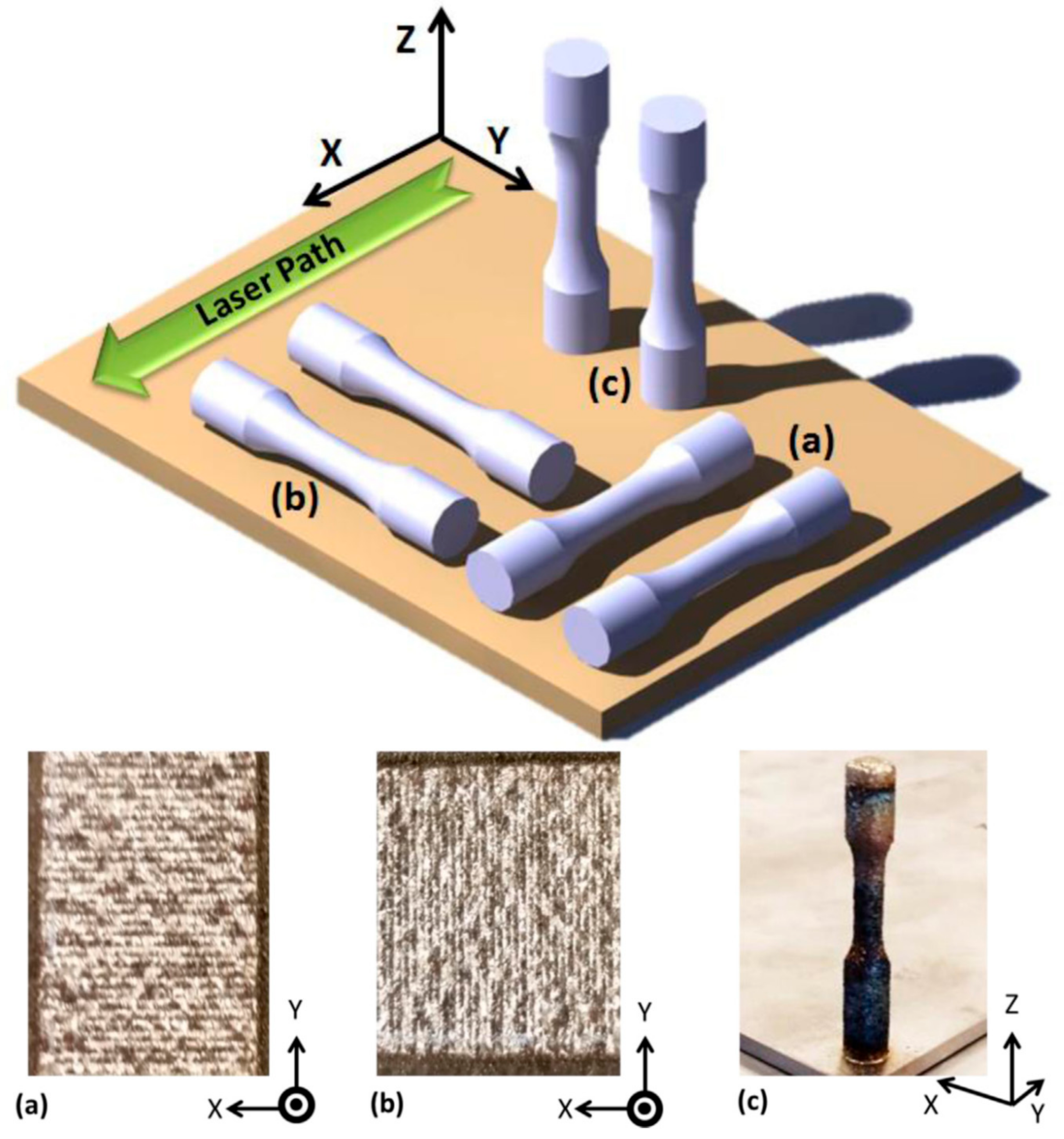
104]. For instance, Shamsaei et al. produced tensile samples in different directions (
Figure 13), building in the direction along the length of the tensile sample (X-direction) or depositing perpendicular to the length of tensile samples (Y- or Z-direction) [
18]. They observed that the tensile strength of samples produced in the X-direction is higher than those fabricated in other directions, as underlined by the comparison of data listed in
Table 5.
This anisotropic behavior of DED Ti-6Al-4V is attributed to the presence of different interfacial layers in different directions, implying the easy formation of shear bands during the testing of the corresponding samples [
65,
105]. These results provide further support for the hypothesis that various cooling rates in two different directions lead to the formation of different microstructures and consequently different mechanical properties. For example, in the X-direction the time between consecutive layers is longer than in other directions because of the presence of a long deposition path that results in higher cooling rates and consequently a finer microstructure and higher tensile strength [
31].
The effect of post treatment on the tensile properties of Ti-6Al-4V parts was investigated by Kobryn et al. [
65]. They demonstrated that by HIPing the components at 900 °C and 100 MPa for 2 h it would be possible to densify the DED components and improve the ductility and elongation at break of the part. Indeed, the growth of alpha laths at high temperature during HIP implies a decrease in the tensile strength of the part and an increase in its elongation.
By understanding the effect of the thermal history on microstructure and mechanical properties of the DED samples, it is possible to limit their anisotropy, for instance by using different scanning strategies. In fact, Koborn and Semiatin measured the tensile properties of Ti-6Al-4V samples produced by using 90° rotation between the layers. Under these conditions, the tensile properties of DED components in the X- and Y-direction are almost equal (
Figure 14) [
65]. Koborn et al. used gas atomized pre-alloyed Ti-6Al-4V powder. In order to evaluate the effect of various building systems on microstructure evolution during the DED process a low power Nd:YAG based system and a high power Co
2 system was used. The influence of power and scan speed on the microstructure and consequently the mechanical properties of the DED component was undertaken by employing ±20% variation from the manufacturer’s recommended setting.
On the basis of these results, the anisotropy in mechanical properties of DED components may be attributed to the columnar grain morphology and also to the limited grain growth that generally takes place in the direction perpendicular to the columnar grain [
65].
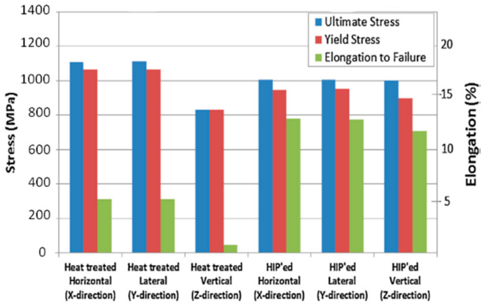
Furthermore, Qiu et al. demonstrated that UTS and YS of DED Ti-6Al-4V samples which are built at the optimum parameters (1360 W as laser power, 800 mm/min as a laser scanning speed, 7 g/min as a powder feeding rate and 0.84 mm as a Z step) are high while their elongations are low (
Table 6). Indeed in this work, a 6.5-axis TRUMPF blown powder system with a 4 kW disc laser were used to deposit the parts and the gas atomized powder was delivered into the melt pool by means of a coaxial nozzle. The fine microstructure and residual stress remained within the specimen were indicated as the main factors responsible for the strength of the DED samples. In addition, the evaluation of the fracture surfaces suggested that the main source of failure is the lack of fusion pores which are very harmful for mechanical properties [
88].
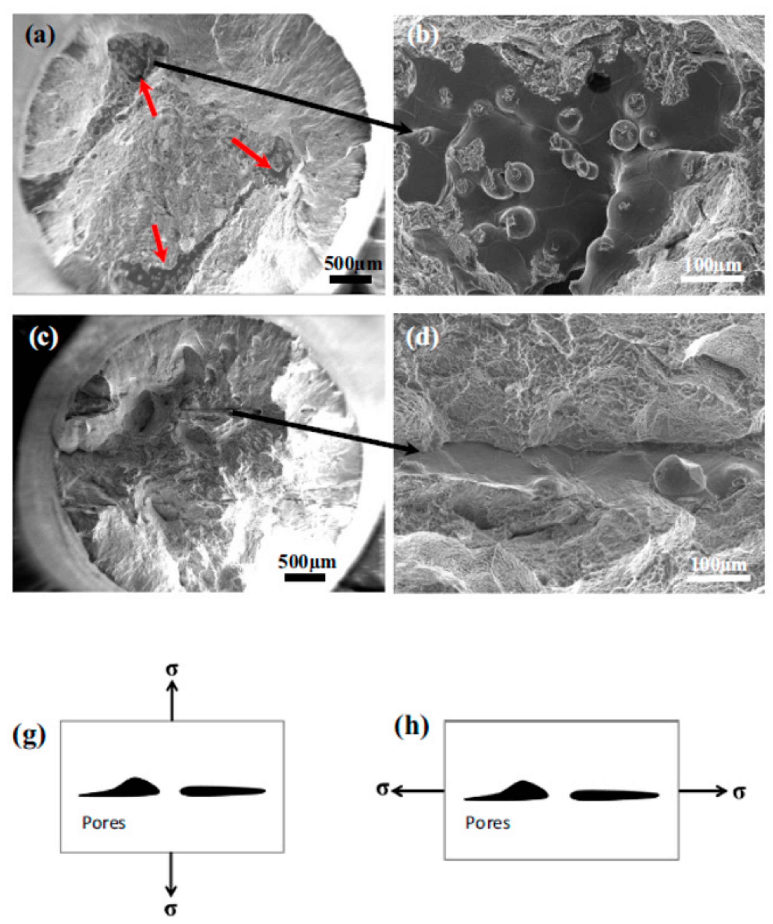
The fracture surface of as-DED samples built in the vertical direction is completely different from that of the horizontal specimens (
Figure 15). In the vertical direction it is possible to recognize a few large opened-up voids with smooth surfaces that consist of some un-melted or partially melted powder particles. This type of fracture surface implies that the fractured layer was not completely remelted during the consecutive deposition. On the other hand, the fracture surface of horizontal samples consists of closed pores or seams that are typical features of fracture surfaces. It was concluded that this significant discrepancy in the fracture surfaces could be attributed to the relation between the direction of loading during the tensile tests and the orientation of pores usually placed at the inter layer boundaries. Several studies have shown that , in the case of DEDed horizontal samples, since loading is nearly parallel to the flat pores, the pores are sealed and closed during the loading whereas, in the case of vertical ones, the pores start to be torn apart along the loading direction [
88,
104].


