Article

Design of Wing Root Rotation Mechanism for Dragonfly-Inspired Micro Air Vehicle

Robotics Group, Korea Institute of Industrial Technology, Ansan-si 15588, Gyeonggi-do, Korea
*
Author to whom correspondence should be addressed.
Appl. Sci. 2018, 8(10), 1868; https://doi.org/10.3390/app8101868
Submission received: 7 August 2018 / Revised: 28 September 2018 / Accepted: 29 September 2018 / Published: 10 October 2018
(This article belongs to the Special Issue Advanced Mobile Robotics)

Abstract

:
This paper proposes a wing root control mechanism inspired by the drag-based system of a dragonfly. The previous mechanisms for generating wing rotations have high controllability of the angle of attack, but the structures are either too complex or too simple, and the control of the angle of attack is insufficient. In order to overcome these disadvantages, a wing root control mechanism was designed to improve the control of the angle of attack by controlling the mean angle of attack in a passive rotation mechanism implemented in a simple structure. Links between the proposed mechanism and a spatial four-bar link-based flapping mechanism were optimized for the design, and a prototype was produced by a 3D printer. The kinematics and aerodynamics were measured using the prototype, a high-speed camera, and an F/T sensor. In the measured kinematics, the flapping amplitude was found to be similar to the design value, and the mean angle of attack increased by approximately 30° at a wing root angle of 0°. In the aerodynamic analysis, the drag-based system implemented using the wing root control mechanism reduced the amplitude of the force in the horizontal direction to approximately 0.15 N and 0.1 N in the downstroke and upstroke, respectively, compared with the lift-based system. In addition, at an inclined stroke angle, the force in the horizontal direction increased greatly when the wing root angle was 0° at the inclined stroke angle, while the force in the vertical direction increased greatly at a wing root angle of 30°. This means that the flight mode can be controlled by controlling the wing root angle. As a result, it is shown that the wing root control mechanism can be applied to the MAV (micro air vehicle) to stabilize hovering better than the MAV using a lift-based system and can control the flight mode without changing the posture.

1. Introduction

Small birds and insects are good objects to mimic for developing a micro air vehicle (MAV) for stable flight at low Reynolds fluid [1,2,3,4,5,6,7]. The RoboBee developed by researchers at Harvard [1], the robot hummingbird of DARPA [2], the beetle robot of Konkuk University [3], and the tailless aerial robot inspired by the flies of Delft [7] are representative robots developed by mimicking the flight of small birds and insects. Among the insects mimicked, the dragonfly has the most stable hovering ability, the ability to switch flight modes without changing posture, and ability to fly backwards [8,9]. In order to achieve this high maneuverability, the dragonfly uses characteristics such as the phase difference between the forewing and hind wing [8,10,11,12], independent control of each wing [13], and a drag-based system in hovering flight [14,15].
Among these characteristics, we focus on the drag-based system. Most insects, except the dragonfly, use a lift-based system in which they stroke their wings in the horizontal direction of the body during hovering. On the other hand, dragonflies use a drag-based system in which they stroke their wings in an inclined direction to the body. This drag-based system not only provides more stable flight but also improves maneuverability by maintaining posture when changing flight mode [14,15]. Dragonflies that use a drag-based system rely on drag force for 76% of the force required for hovering, and most vertical forces for hovering flight are obtained on the downstroke [15]. For this reason, in order to maximize their vertical force, dragonflies increase the drag force through a large angle of attack during the downstroke, while minimizing the drag force through a small angle of attack in the upstroke [16,17].
The aforementioned angle of attack is an important factor that enables most insects, including dragonflies, to control the magnitude and direction of the force generated when flapping their wings [18]. Most small birds and insects produce an angle of attack by rotating their wings in the longitudinal direction when the direction of the flapping stroke is reversed, such as from the upstroke to the downstroke, or from the downstroke to the upstroke [19,20]. These wing rotations are divided into passive rotation using aerodynamic force and inertial force and active rotation that is directly controlled through the muscles. It is not known exactly what type of wing rotation insects use, but it has been proven that passive rotation explicitly occurs during flapping [21]. A variety of mechanisms for generating wing rotation for the FW-MAV (flapping wing micro air vehicle) have been proposed in studies mimicking the flight characteristics of insects.
These mechanisms are divided into passive [22] and active rotation mechanisms [23,24] like insect wing rotation. A passive rotation mechanism has been produced by creating a wing frame using a flexible material or loose membrane. For the active rotation mechanism, a method of artificially generating rotation using a spring, and a method of simultaneously implementing flapping and rotation with a single actuator using a spatial four-bar link mechanism have been presented. Various attempts have been made to develop a wing rotation mechanism, but there is a clear limit to mimicking the drag-based system of dragonflies. In the case of the active rotation mechanism, since wing rotation is directly generated using the power of an actuator, it is suitable to implement the desired movement through mechanical design. Moreover, the flapping pattern is easily switched from an asymmetric flapping pattern to a symmetric flapping pattern or vice versa by adding degrees of freedom to the MAV. However, this mechanism is difficult to apply in practical MAV development. The reason is because not only is the structure complex, such that the weight of the airframe increases, and friction and torsion occur to a large extent, but additional energy is also required to generate wing rotation. On the other hand, the passive rotation mechanism has a relatively simple structure and is widely used in the development of MAV [1,2,3,4,5,25,26]. A passive rotation mechanism has also been developed to control the magnitude of the angle of attack by adding degrees of freedom to the wing roots in a passive rotation mechanism in which the wing’s membrane is loosely constructed. The passive rotation mechanism, which depends on the proposed external force, is suitable for developing an MAV with the same angle of attack in the up-down stroke, such as a symmetric flapping pattern. However, it is not suitable for developing MAVs with asymmetric flapping patterns that require a different angle of attack in up-down strokes. Thus, both proposed wing rotation mechanisms have limitations in terms of mimicking the drag-based system of a dragonfly.
The study proposes a mechanism that mimics the flight characteristics of dragonflies, using a drag-based system for hovering flight and a lift-based system for forward flight. The mechanism can be applied to an MAV using a passive rotation mechanism and can implement an asymmetric flapping pattern by changing the mean angle of attack. The proposed mechanism consists of a slide-crank mechanism designed to operate independently of flapping. The flapping motion was implemented using a spatial four-bar link mechanism, while the passive rotation mechanism was fabricated using the design parameters of the wing, optimized for the symmetric flapping pattern from previous research [27]. A high-speed camera was used for kinematic analysis of the prototype, and force measurement tests were conducted to determine whether the horizontal force amplitude of the drag-based system implemented by the proposed mechanism was reduced compared with that of the lift-based system, as well as the force direction variations with respect to changes in the wing root angle.

2. Flight Characteristics of Dragonflies

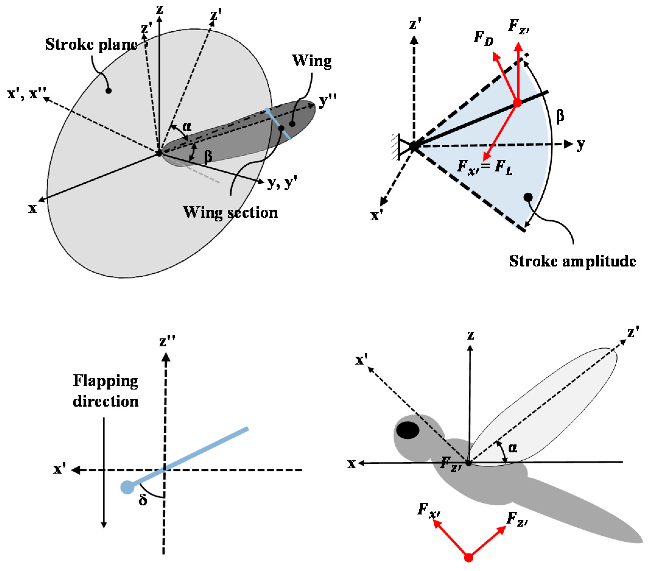
2.1. Kinematics of Dragonfly Flight

The kinematics [28,29] and aerodynamics [14,15,16,20,30,31] of dragonflies have been studied extensively in the past. Wang analyzed the stroke amplitude and wing angle of attack placed at 70% from the wing root in forward flight using an ultrahigh-speed camera [28]. In the same way, Azuma measured the stroke amplitude and angle of attack in hovering flight of the dragonfly [29]. However, the maximum and minimum stroke angle and mean angle of attack must be clearly defined in order to proceed with the aerodynamic experiment on the MAV. In this study, these parameters were defined as listed in Table 1, and the coordinate system of the kinematics is shown in Figure 1. The figure shows the flapping motion in the relative coordinate system x′y′z′ rotated by α with respect to the absolute coordinate system xyz, where α is the stroke angle, β is the stroke amplitude, and δ is the angle of attack.

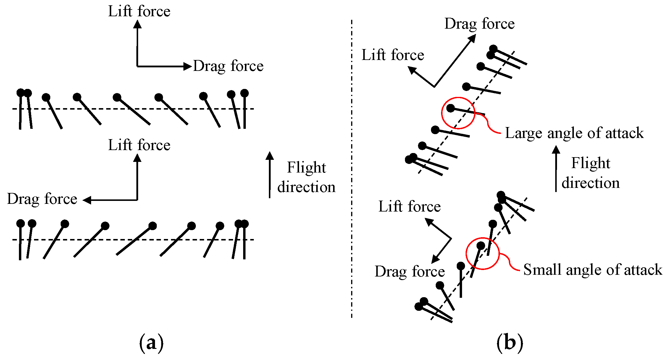
2.2. Aerodynamics of Dragonfly Flight

The systems used by organisms for swimming or flying are divided into drag-based systems and lift-based systems, depending on the type of force [14,15]. The lift-based system uses lift force in the manner of most fish or flying insects. Lift forces are obtained through up-down strokes, whereas drag force is generated in the opposite direction with the each up-down stroke, and the net force generated for one cycle is close to zero, as shown in Figure 2a. The drag-based system is based on the drag force, used in rowing locomotion or jellyfish swimming. In order to generate enough drag force to fly or swim, dragonflies flap their wings, and with each down-stroke maintain a large angle of attack to increase the drag force. In contrast, the upstroke minimizes the drag force by flapping with a small angle of attack, as shown in Figure 2b. This method allows the creature to generate force in the direction of movement through the drag force.
Wang [14] mentioned that the drag-based system is more stable than the lift-based system in stationary flight, while the lift-based system has superior performance in forward flight. In addition, Vogel [15] experimentally proved that the drag-based system is more stable in stationary flight. Unlike most insects that use a lift-based system, dragonflies use both a drag-based system in hovering flight and lift-based system in forward flight. This system conversion is achieved by changing their angle of attack, which gives them more stable and superior flight abilities.
Dickinson experimentally defined lift and drag coefficients for when the thin wing moves in low Reynolds fluid as the following equations.
C L = 0.225 + 1.58 sin ( 2.13 α 7.20 ) ,
C D = 1.92 1.55 sin ( 2.04 α 9.82 ) .
where C L is the lift coefficient, C D is the drag coefficient, and α is the angle of attack. The equation shows that the drag coefficient is a function of the angle of attack. In the relationship between the angle of attack and drag force, in order to use the drag-based system at hovering, the dragonfly increases the drag force using a large angle of attack at the downstroke and minimizes the drag force using a small angle of attack at the upstroke. On the other hand, in forward flight, the dragonfly flies by generating lift force using the same angle of attack in the up-down stroke like other insects. Thus, the rapid conversion from a drag-based system to a lift-based system without changing the stroke angle is achieved by changing the mean angle of attack.

3. Development of a Wing Root Rotation Mechanism

3.1. Passive Wing Rotation Mechanism

In the flight of insects, wing rotation is an essential factor for a positive angle of attack at flapping. To generate the wing rotation passively, this study used a wing rotation mechanism using a loose wing membrane, as shown in Figure 3 [27]. The proposed wing rotation mechanism was fabricated with a wing membrane larger than the designed wing membrane to generate wing rotation, and this changes the angle of attack by rotating the wing root. This wing rotation made by the loose wing membrane not only generates more lift force by the camber wing structure in flight but also increases the efficiency while gliding [32,33,34,35].
The frame of the wing is made of carbon rods to reduce the weight, and the wing membrane is made of 25 μm thick polypropylene film. For the passive rotation of the wing, a polyolefin tube attached at the leading edge and root of the wings reduce the friction at wing rotation. In addition, two 0.6 mm carbon rods attached to the wing membrane maintain the rigidity of the wing after rotation, as shown Figure 3a.

3.2. Concept of Wing Root Rotation Mechanism

The purpose of this study is to develop a passive wing rotation mechanism that mimics the flight characteristics of dragonflies and can change the mean angle of attack by rotating the wing root. The mean angle of attack changes by wing root rotation with respect to the horizontal direction of the wing when the wing has the same angle of attack at each up-down stroke. Figure 4 shows the variation of the wing angle of attack range with this passive wing rotation mechanism. We developed the mechanism for changing the mean angle of attack based on a slide-crank link mechanism, where the crank is the wing root and rotates on the y″-axis.
To obtain a lift-based system with the same angle of attack at each up-down stroke, the wing root direction should be perpendicular to the stroke direction. However, the lift-based system of the wing root rotation mechanism has a singularity position problem when designed using a general slide-crank link mechanism. In order to solve this problem, we designed a slide-crank link mechanism with a three-bar link, as shown Figure 5. The wing root of the crank link with the three-bar link is located below the general slide-crank link mechanism’s wing root. Therefore, the crank link is located above the singularity position when the wing root direction is perpendicular to the stroke direction. As a result, the wing root can rotate without singularity.

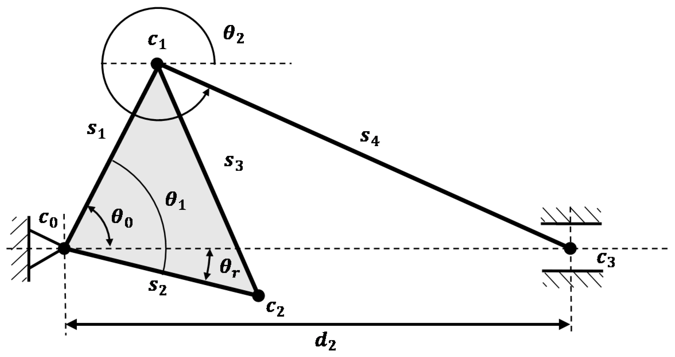
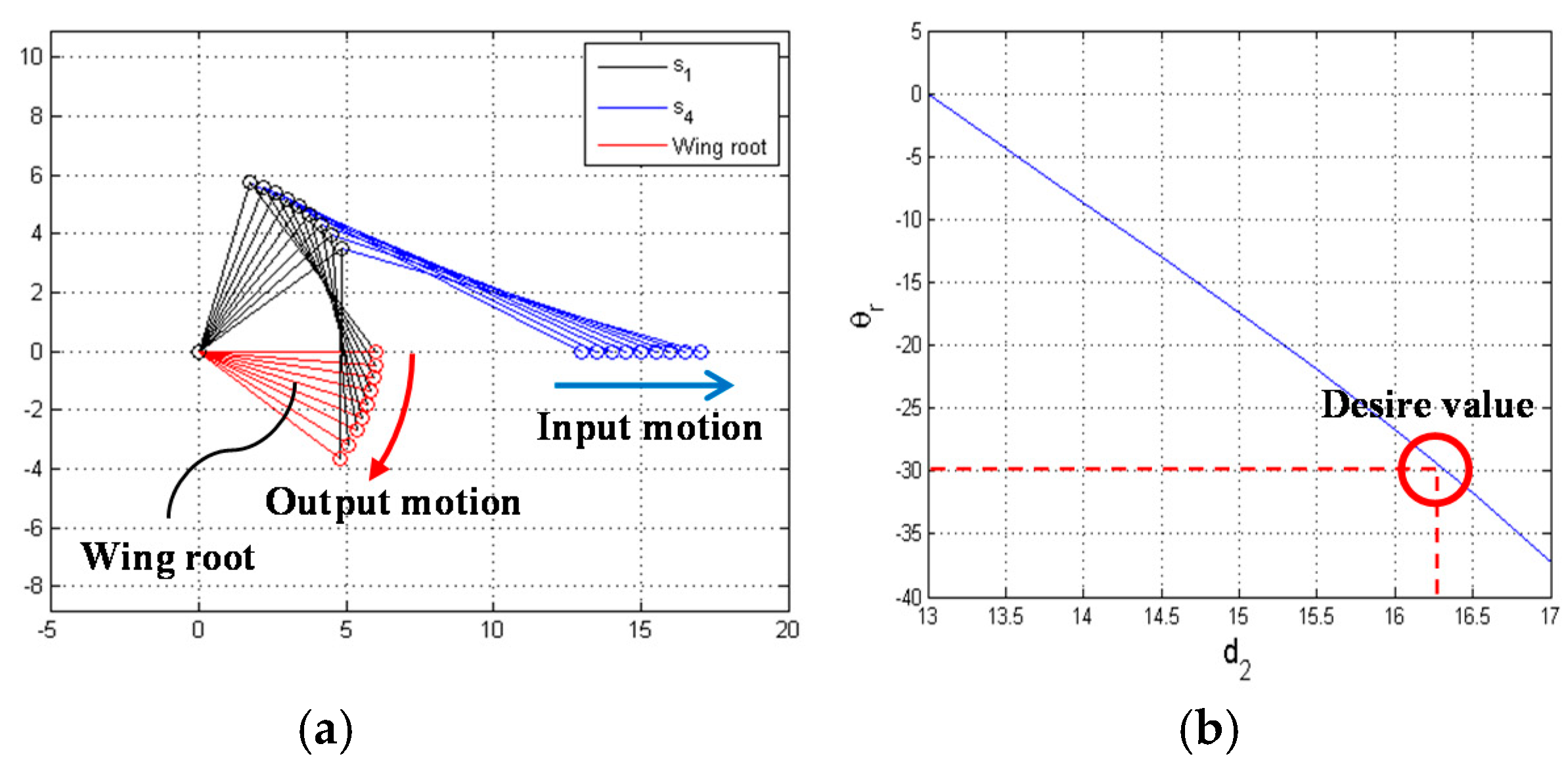
3.3. Kinematics of Wing Root Rotation Mechanism

Figure 6 shows a schematic of the proposed slide-crank mechanism with the three-bar link to define the relationship among variables, and the kinematics of this mechanism was analyzed by vector analysis.
The wing root angle θ r is defined by θ 0 and θ 1 , as in Equation (3).
θ r = θ 1 θ 0
where θ 1 is a constant value, and θ 0 is a dependent variable described by d 2 , which is an independent variable.
θ 0 = cos 1 ( d 2 2 + s 1 2 s 4 2 2 s 1 d 2 )
As a result, θ r can be obtained as Equation (5) by substituting (4) into (3).
θ r = θ 1 cos 1 ( d 2 2 + s 1 2 s 4 2 2 s 1 d 2 )
After the kinematic analysis, each variable was defined for the design of the wing root control mechanism in Table 2. s 1 , minimum value of d 2 , and θ 2 ( θ 0 + 180 ° ) are the values to avoid physical collision. These design parameters were obtained by trial and error in 3D modeling. s 4 was obtained by applying the proposed values to (6).
s 4 = d 2 2 + s 1 2 cos 2 ( θ 2 ( θ 0 + 180 ° ) ) s 1 2 + s 1 cos ( θ 2 ( θ 1 + 180 ° ) )
Lastly, θ 1 , which makes θ r equal to zero when d 2 is the minimum, is defined by (7).
θ 1 = cos 1 ( s 1 2 + d 2 2 s 2 2 2 s 2 d 2 )
Figure 7 shows the results of the kinematics calculated by the defined design parameters. Figure 7a shows the simulation output motion ( θ r ) with respect to input motion ( d 2 ) and describes that the output motion is normally driven by input motion. The blue line is the s 4 link, the red line is the s 4 link, the blue dot is the input motion of linear motion, and the red dot is output motion of the wing root.
To implement the lift-based system and drag-based system of the dragonfly, each mean angle of attack should be 0° and 30°. Therefore, it is necessary to define the input variable for each system. The wing root angle for the lift-based system was defined as 0 at the above link optimization, but d 2 for the drag-based system, which is −30°, was not defined. Figure 7b shows relationship between d 2 and θ r , and the desired value of d 2 when θ r is −30°. As a result, we confirmed that the MAV implements a drag-based system when d 2 is 16.25 mm. Table 2 lists the design parameters of the wing root rotation mechanism.

4. Design of Flapping Mechanism

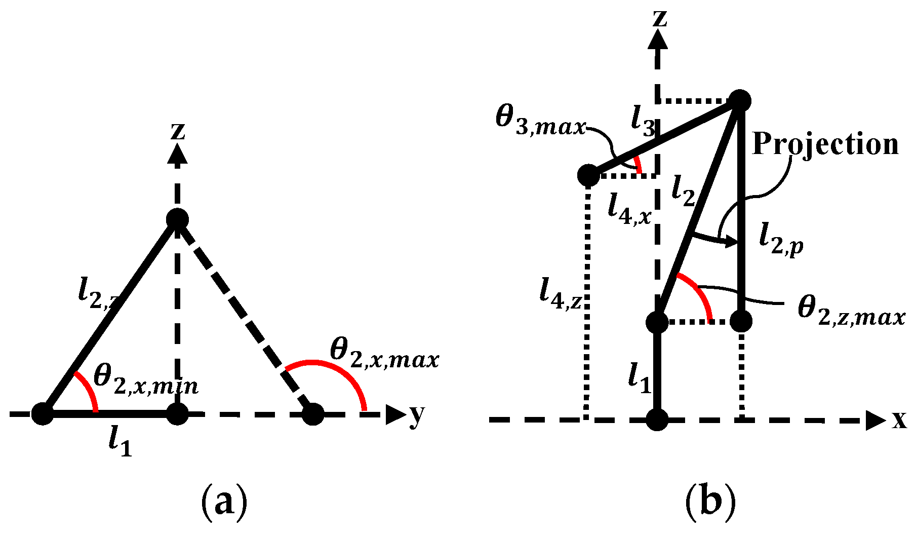
4.1. Analysis of Kinematics

In this work, we used the spatial four-bar-based flapping mechanism to convert from rotational motion to a couple of flapping motions using a rotary actuator. The spatial four-bar-based flapping mechanism consists of two spherical joints, a crank link, and a flapping link. In this mechanism, the factor considered for the design is the limited range of spherical joints. Figure 8 shows the angle limit of the spherical joint; when the y-axis is the joint axis, it has an angle limit of −30° to 30° in the x-axis direction and z-axis direction.
The schematic of the flapping mechanism is shown in Figure 9, where O 1 , O 2 are the three-axis spherical joints, O 0 , O 3 are one-axis joints; θ 1 is the crank angle; θ 3 is the flapping angle; and θ 2 , x , θ 2 , z are the angles of the spherical joint. The kinematics of the flapping mechanism was analyzed by vector analysis; the input variable is θ 1 , which is the crank angle. The flapping angle ( θ 3 ) is defined by the crank angle and expressed as (8).
θ 3 = sin 1 ( l 2 2 ( k x 2 + k y 2 + k z 2 + l 3 2 ) 2 l 3 k x 2 + k z 2 ) sin 1 ( k x k x 2 + k z 2 )
In the equation, k x = l 4 , x , k y = l 4 , y l 1 cos ( θ 1 ) , and k z = l 4 , z l 1 sin ( θ 1 ) . Then, using the defined θ 3 , the spherical joint angles θ 2 , x , and θ 2 , z are described by (9) and (10), respectively.
θ 2 , x = cos 1 ( k x + l 3 cos ( θ 3 ) l 2 )
θ 2 , z = cos 1 ( k y l 2 sin ( θ 2 , z ) )

4.2. Define Link Length of Flapping Mechanism

We defined the link length of the flapping mechanism so that the stroke amplitude is within a given range, and θ 2 , z , θ 2 , x are within the angle limits of the spherical joint. The mechanism was determined to have a stroke amplitude of −40° to 40°, an angle of the x-axis of the spherical joint within 60–120°, and an angle of the z-axis of the spherical joint within 60–90°. In the processing, the limit of the z-axis angle of the spherical joint was set as 90° rather than 120° to avoid physical collision at 90°. The link length was defined in three steps: (1) the determination of l 2 , p with respect to the x-axis limit of the spherical joint; (2) the calculation of l 3 , l 4 , z with respect to the stroke amplitude; and (3) the determination of l 4 , x with respect to the z-axis limit of the spherical joint.
To determine the link length with respect to the θ 2 , x range, l 2 , p , which is projected on the y-z plane of l 2 , as shown in Figure 10a, is defined as (11).
l 2 , p = l 1 cos ( θ 2 , x )
The maximum and minimum values of θ 2 for calculating l 2 , p are the same because the central axis of the crank link and flapping link are located on the same plane, as shown in Figure 10b. This means that if the link value is determined for one of the maximum and minimum values, then the other value is also defined. Therefore, l 2 , p was obtained by applying θ 2 , m i n to (11), after θ 2 , m i n was defined as 77°.
Second, in order to calculate l 3 and l 4 , z , and having the stroke amplitude defined in Table 1, the relation between l 3 and l 4 , z is expressed as (12) and (13) when θ 3 is the maximum and minimum, respectively.
l 3 , max = ( l 2 , p + l 1 l 4 , z ) sin ( θ 3 , max )
l 3 , min = ( l 2 , p l 1 l 4 , z ) sin ( θ 3 , min )
In addition, to determine l 3 and l 4 , z for the desired stroke amplitude, the object function was defined as (14), which is the absolute value of the difference between (12) and (13).
O ( l 3 , l 4 ) = | l 3 , max l 3 , min |
Afterwards, l 3 and l 4 , z were determined by the defined object function and line search method. l 2 , p is different from the previously defined value, but the defined l 2 , p was used because the difference in values is within the tolerance range. Finally, we defined the link length for the angle limit of θ 2 , z , as shown in Figure 10b; θ 2 , z has the maximum value when θ 3 is the maximum. The maximum value of θ 2 , z was defined as 80°, and l 4 , x was obtained by applying the variables to (15).
l 4 , x = l 3 cos ( θ 3 ) l 2 , p tan ( θ 2 , z , max )
The values of θ 3 , θ 2 , x , θ 2 , z , and the link lengths obtained from the kinematic equations are summarized in Table 3. Figure 11 shows each angular value according to the crank angle change. In the graph, we confirmed that θ 2 , x and θ 2 , z are within the angle limit of the spherical joint, and θ 3 is within the desired stroke amplitude.

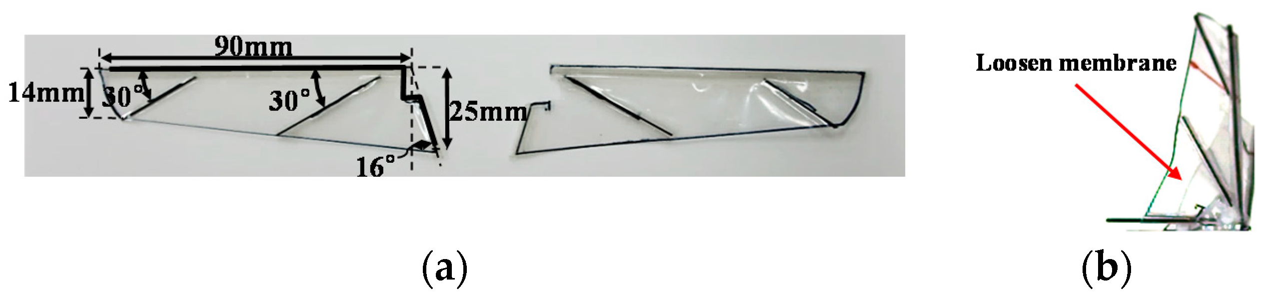
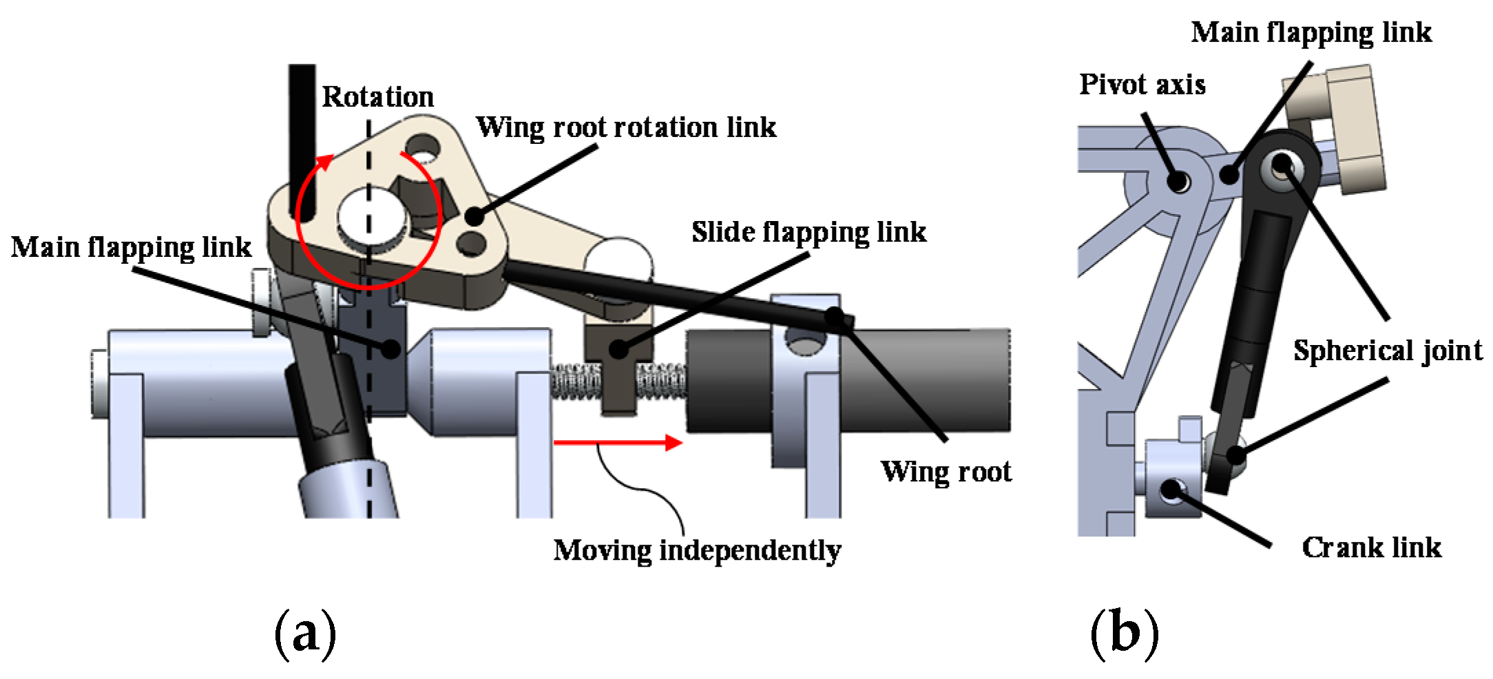
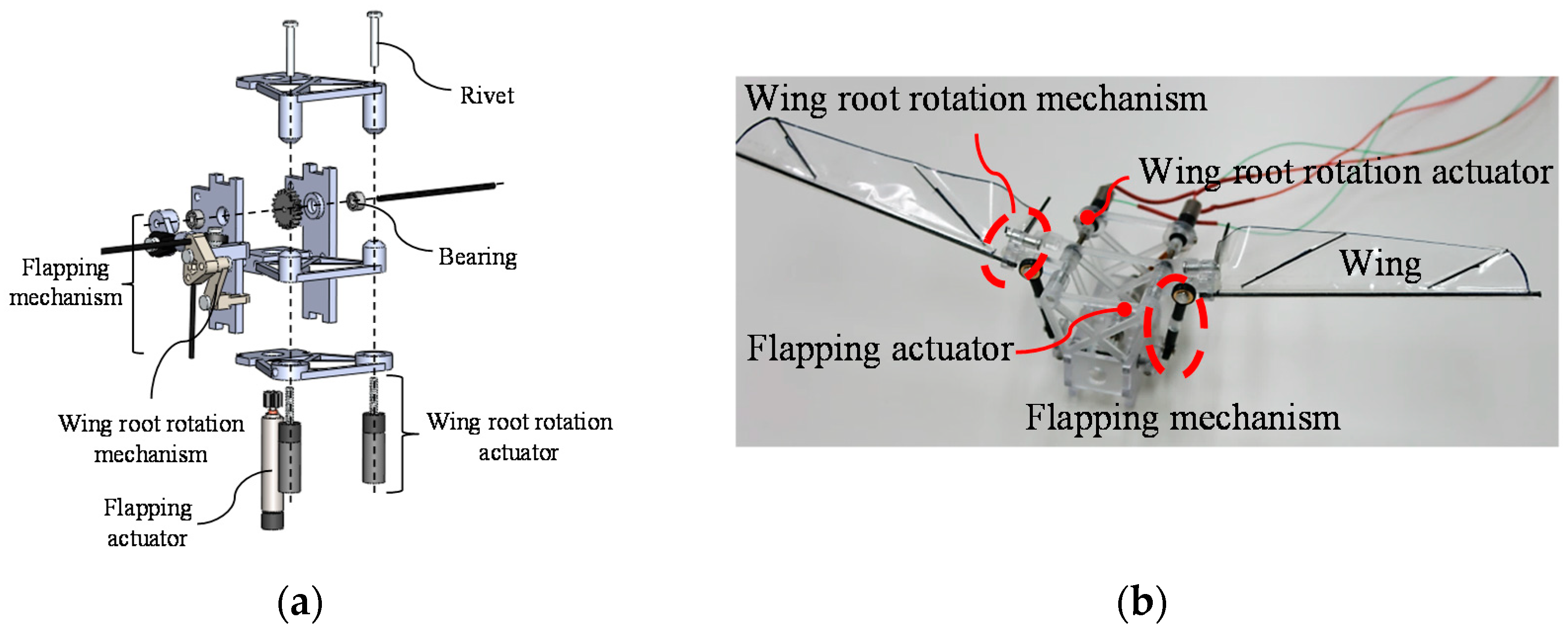
5. Design and Fabrication of Prototype

In order to combine the wing mechanism using a rotary actuator and the wing root rotation mechanism using a linear actuator, both mechanisms must be designed to move independently. Figure 12a shows the side view of the prototype design for the rotation mechanism, and Figure 12b shows the front view of the prototype design for the flapping mechanism. Figure 12a shows the main flapping link, slide flapping link, and wing root rotation link for independently driving two actuators. The wing root rotation link rotates with two flapping links as pivot axes and always moves in the same plane as the flapping link. The slide flapping link rotates with the spindle of the ball screw as the pivot axis and performs linear motion as the nut of the ball screw. Because the slide flapping link can simultaneously implement rotary motion and linear motion as the nut of the ball screw, the designed prototype has both independent flapping motion and wing root rotation motion.
Figure 13a,b shows the designed prototype and fabricated prototype, respectively. The prototype was designed using 3D CAD (Solidworks 2013, Dassault Systemes, France) software and design parameters determined for link optimization. The parts of the prototype, except a spherical joint link, were manufactured by an SLA (stereo lithography apparatus)-type 3D printer (ProJet 5000, resolution: 100 μm, 3D Systems, Rock Hill, SC, USA) using PC (polycarbonate). The joints were fixed with a 2 mm rivet for low friction and to affix without additional processing. The actuator for flapping is an EC6 (φ6, brushless, 2-watt, Hall sensors, maxon motor, Suisse, www.maxon-motor.com), the controller is a DEC 24/2, and a 37.5:1 gearbox ratio was used for the flapping mechanism. The LCP06-A03V-0026(D&J WITH Co., Geumcheon-Gu, Seoul, Korea) was used as the actuator of the wing root rotation mechanism, and 2 mm bolt was used for the spindle.

6. Experiment and Analysis

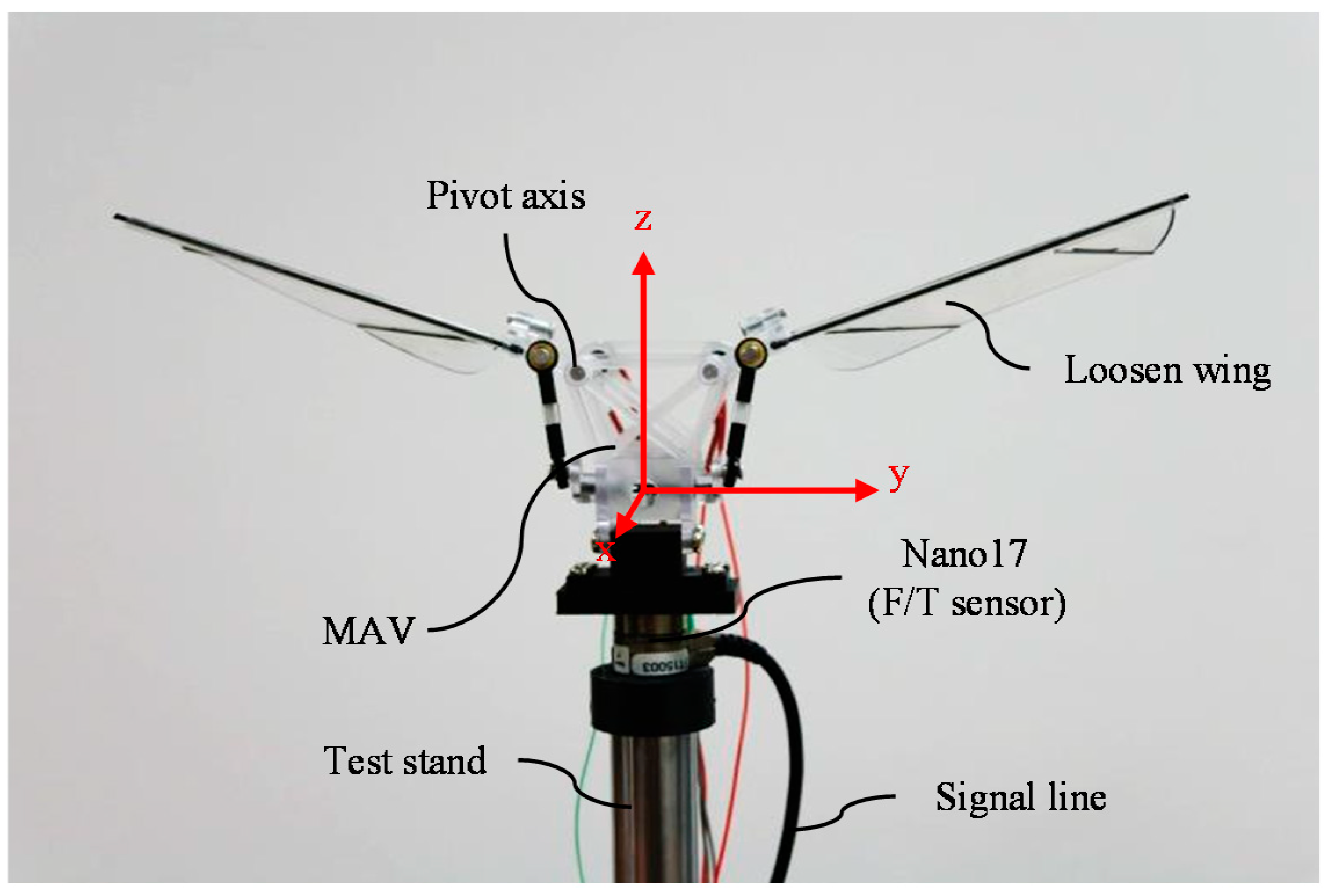
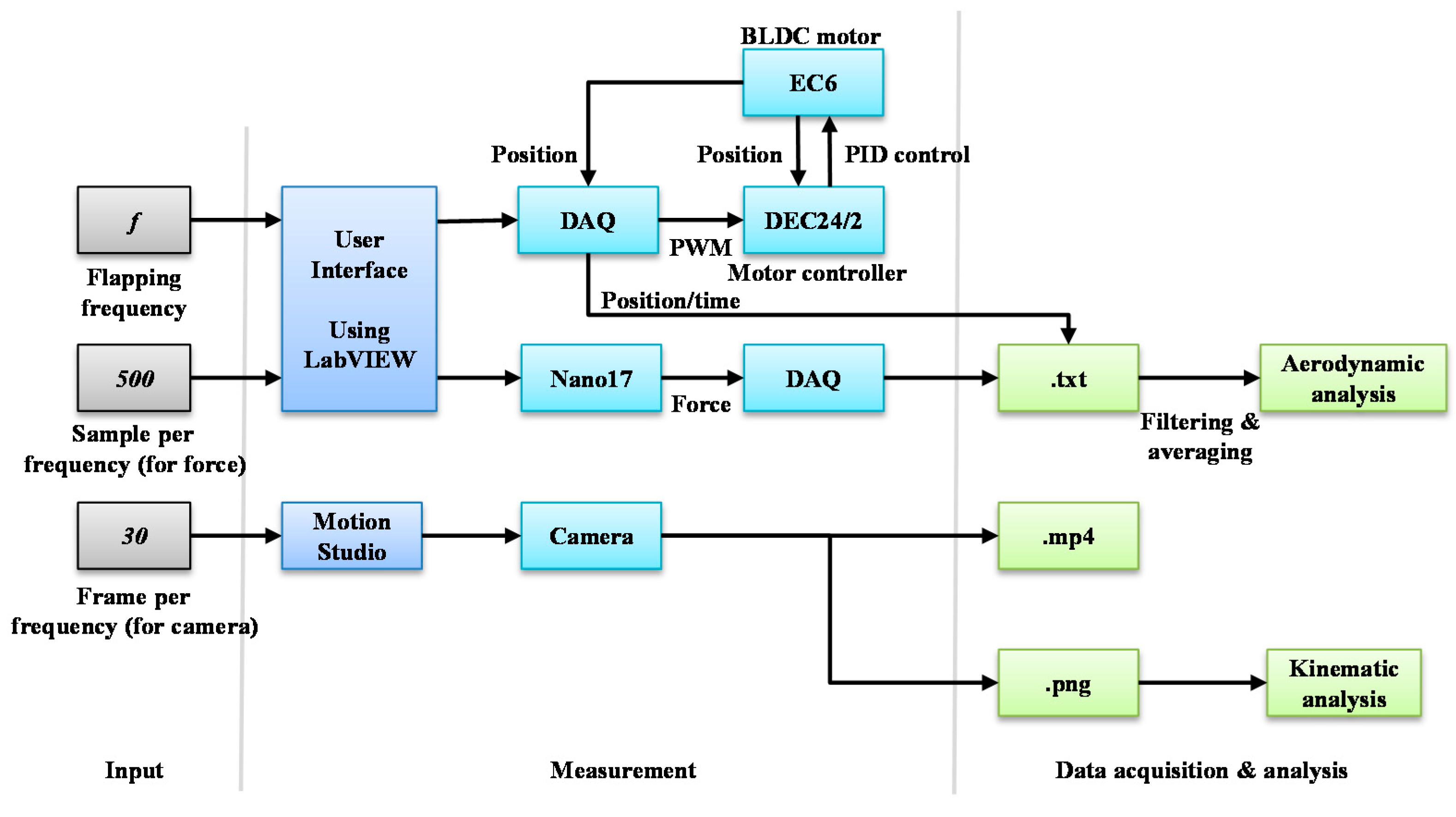
6.1. Experimental Setup

This study proposes a mechanism for using the drag-based system in a hovering and lift-based system in forward flight by varying the mean angle of attack. We measured two factors to verify whether the drag-based and lift-based systems were implemented according to wing root rotation changes in the proposed mechanism. First, we took the front and side views of the MAV using a high-speed camera and measured the kinematics using the photographs. To obtain 30 images per cycle of flapping, the MAV was taken at a rate of 450 FPS (frames per second) at flapping frequency of 15 Hz. The angle of attack at flapping was obtained by measuring the length of the wing membrane at 70% from of wing root of the image.
Second, the aerodynamic force was measured by a force sensor. Figure 14 shows the force sensor, test stand, and signal line. High sampling rates and high resolution were required for force measurements during flapping. Therefore, the Nano 17 F/T sensor (resolution: 1/80 N, ATI Industrial Automation, Apex, NC, USA) was used for force measurement. The x-axis of the force sensor was installed at the front of the MAV and the z-axis was installed along the vertical direction of the MAV to measure data from each lift and drag. The tests proceeded at a flapping frequency of 10–15 Hz, and to obtain 500 data points per flapping cycle, the data was measured at 5000 RPS (rate per second) at 10 Hz and 7500 RPS (rate per second) at 15 Hz. Figure 15 shows the entire flowchart of the force and image data.
According to Caetano et al. [36], it has been determined that the frequency of the aerodynamic force is 2 times higher than flapping frequency, and the inertial force frequency is 3 times higher than the flapping frequency. Therefore, in this study, the measured data were filtered by a lowpass filter with a cutoff frequency 2 times larger than the flapping frequency to estimate the aerodynamic force.

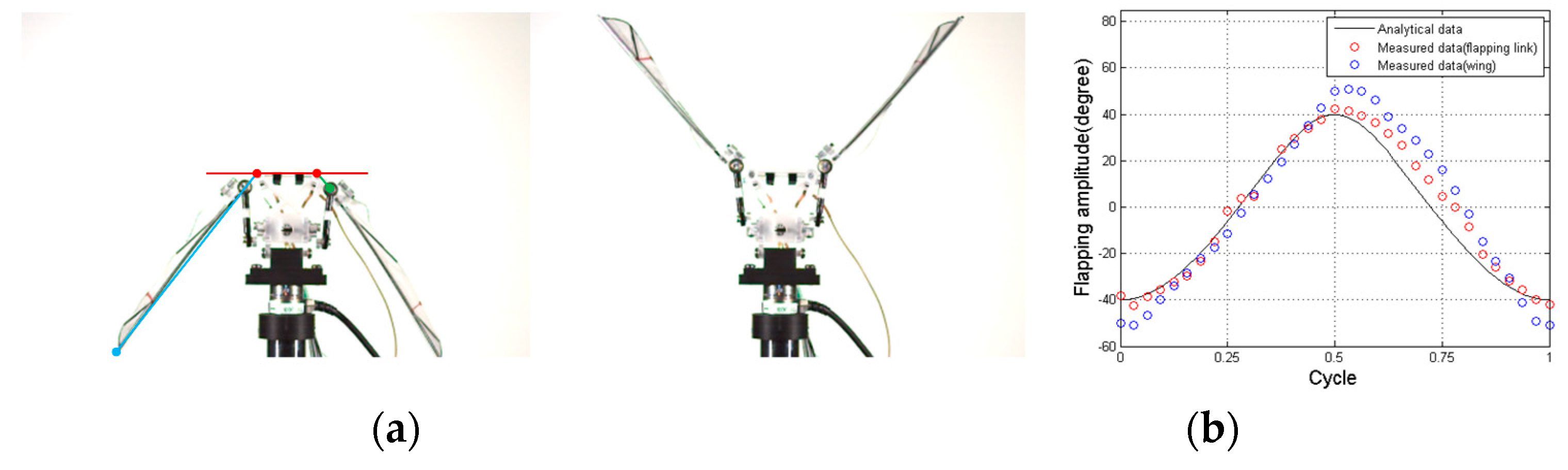
6.2. Analysis of Kinematics

6.2.1. Stroke Amplitude

Figure 16a shows the MAV at the minimum and maximum amplitudes taken with a high-speed camera. Figure 16b shows the measured amplitude during one cycle of the flapping link and wing by analyzing the image taken. In order to extract the kinematics from the image, the pivot, spherical joint tip, and wing tip were marked. Then, each mark was connected by a line, as shown in the left image in Figure 16a. The kinematics was extracted by measuring the angle between the connected lines. The amplitude of the flapping link has an error of approximately 4° with the designed amplitude by the joint’s tolerance. On the other hand, the wing amplitude has an error of approximately 20° and is caused by the flexion of the wing frame.

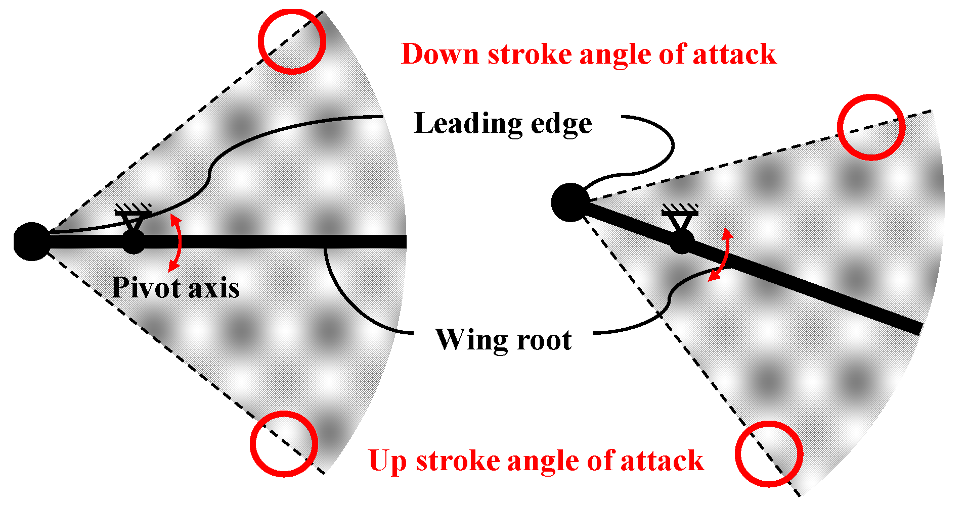
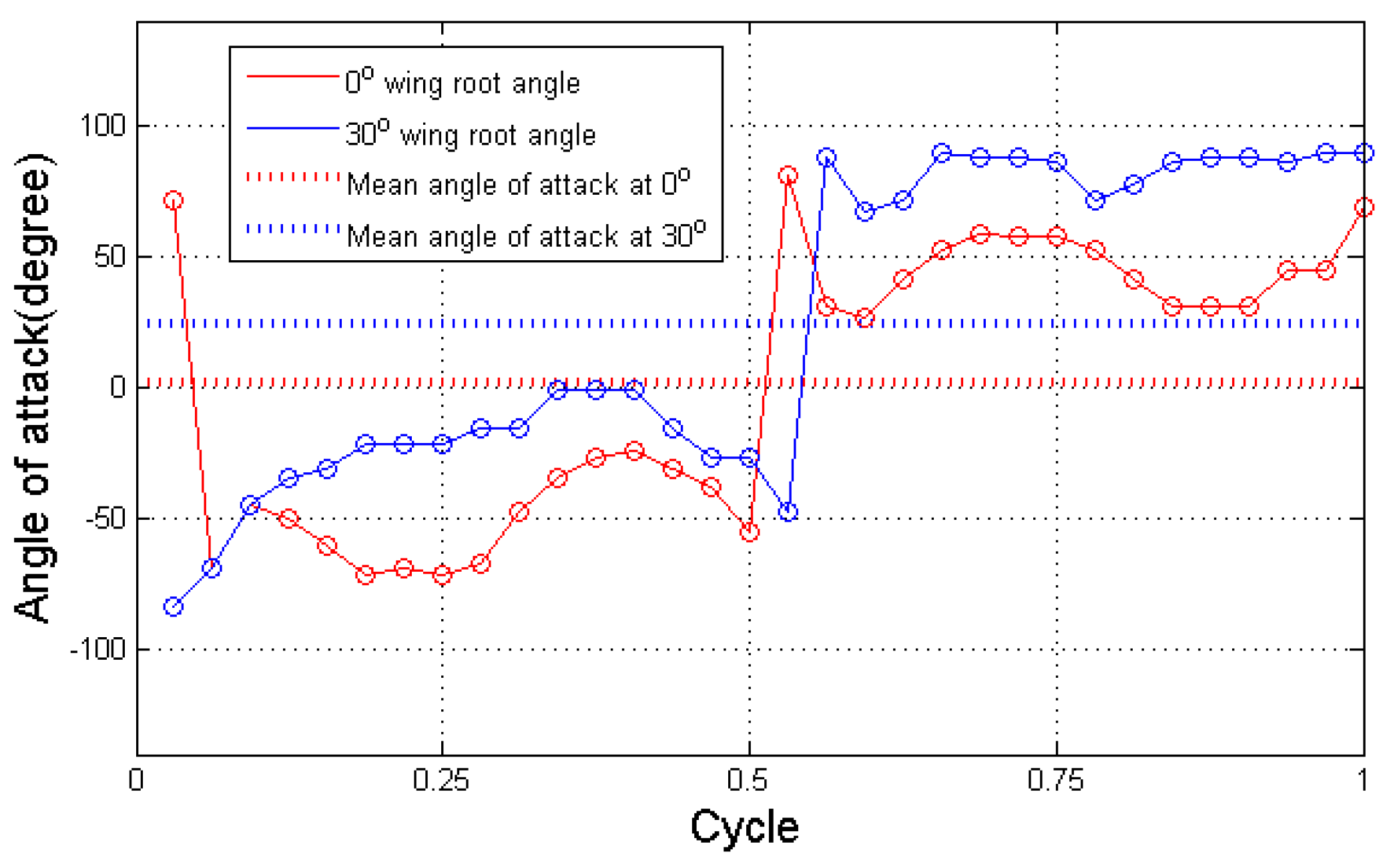
6.2.2. The Wing Angle of Attack

Figure 17 shows each angle of attack at upstroke and downstroke when the wing root angle is 0° and 30°.
Figure 18 shows the angle of attack of each wing at wing root angles of 0° and 30°. The red straight line is the wing root angle of 0°, the blue straight line is the wing root angle of 30°, and the dotted line is the mean of each angle of attack. Since the angle of attack is defined based on the wing root, it has a negative value in the upstroke and a positive value in the downstroke. The angle of attack at a wing root angle of 0° was symmetric with respect to the angle of attack of 0°, and the mean angle of attack was measured close to 0°. On the other hand, the angle of attack at the wing root angle of 30° had a large angle of attack in the downstroke and a small angle of attack in the upstroke, with mean angle of attack of 30°. These results indicate that the wing root angle and mean angle of attack have a linear relationship and that the angle of attack at the flapping of the MAV is similar to that of a real dragonfly.

6.3. Analysis of Aerodynamics

The lift and drag forces acting on the object are given by (16) and (17), respectively, in the quasi-steady model.
F L = 1 2 ρ C L S U 2
F D = 1 2 ρ C D S U 2
where F L and F D are the lift force and drag force, respectively, ρ is the density of air, S is the area of the object, U is the velocity of the object, and C L and C D are the lift and drag coefficients, respectively. Lift force and drag force were defined with respect to wing, and the wing generates a drag force in the opposite direction of the moving direction and a lift force in the vertical direction of the moving direction. In the equation, the lift and drag are proportional to the velocity squared of the object because all parameters except the velocity are constant. F x and F z , which were measured in the experiment, have the relationship indicated in (18) and (19) with F L and F D as shown Figure 1b. Therefore, F x and F z should increase with the flapping frequency squared of the object.
F x = F L
  F z = F D sin ( θ s )  
Figure 19a shows the relationship between each F x , F z and flapping frequency of the MAV for wing root angles of 0° and 30° during flapping. The red dotted line ( F t ) denotes the estimated value of F x and F z of the wing over the flapping frequency square through the characteristics of (16) and (17). The blue straight line is the measured lift force, and the black straight line is F z . Figure 19b shows the difference between the estimated and measured values. The difference between the measured force and estimated value is not over 0.006 N regardless of the flapping frequency, as shown in the figure. Therefore, F x and F z in the proposed MAV wing are proportional to the flapping frequency squared, and it is possible to estimate the force generated by increasing the flapping frequency.
In the left graph in Figure 19a, F x at a 0° wing root angle increases in the positive direction with flapping frequency, while F z increases in the negative direction or appears near 0. On the other hand, F x at a wing root angle of 30°, shown in the right graph, is lower than that of the wing root angle of 0° but has a similar tendency, and F z increases with increasing flapping frequency. A comparison of the two results shows that the magnitude of F x and F z that occurs in the wing changes when the wing root angle changes.
The top graph in Figure 20 shows F z at a 0° wing root angle when the MAV flaps at a frequency of 15 Hz, while the bottom graph shows F z at a 30° wing root angle. The top and bottom image in Figure 20 show the angle of attack when the wing is horizontal to the ground. The top two images indicate the angle of attack at a 0° wing root angle, while the bottom two images indicate the angle of attack at a 30° wing root angle. The force generated is an aerodynamic force, which is F z of the MAV wing. The aerodynamic force at a 0° wing root angle does not show a significant difference when up-down strokes are compared. In contrast, the peak value after vibration due to the inertial force in the downstroke at a 30° the wing root angle means that the wing receives a large average F z . The decreasing tendency after the vibration due to the inertial force in the upstroke means that the wing receives a small average F z . The experimental results demonstrate that flapping at a wing root angle of 30° produces a reasonable average F z in the up-down stroke.

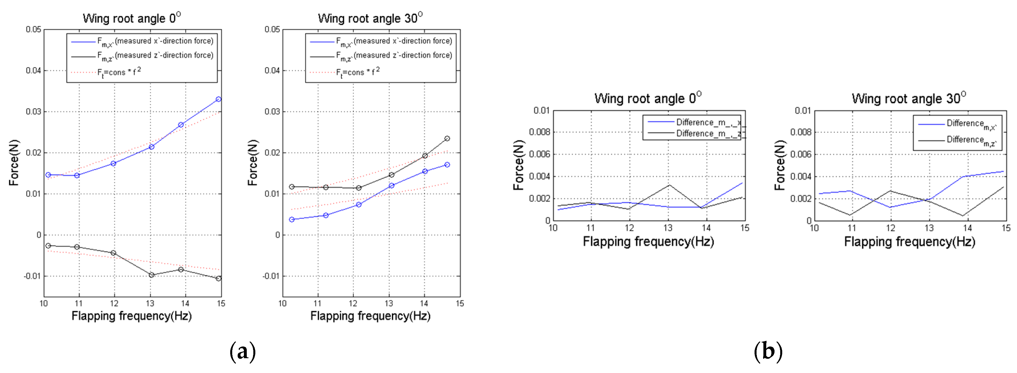
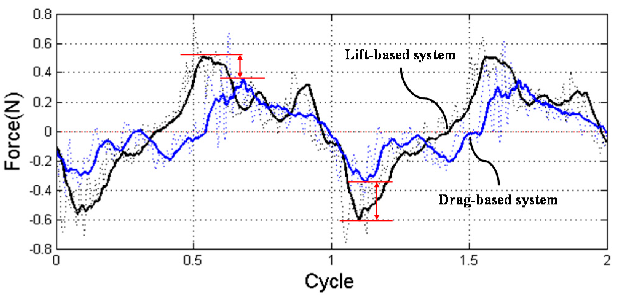
6.3.1. Comparison between Horizontal Force Amplitude

The drag-based system used in hovering by a real dragonfly flaps in the inclined stroke angle direction of 60°, as shown in Figure 21. On the other hand, the direction of F x measured in the study was generated toward the vertical direction of the stroke angle, and the direction of the drag force was generated toward the horizontal direction of the stroke angle. To measure the horizontal force generated by the wing root rotation mechanism at the same stroke angle as the drag-based system of a real dragonfly, the horizontal force was calculated by applying F x and F z measured at the wing root angle of 30° to (21).
F V = F x cos ( θ s ) + F z sin ( θ s )
F H = F x sin ( θ s ) F z cos ( θ s )
where F V is the vertical force, F H is the horizontal force, and θ s is the stroke angle. Since the lift-based system used for hovering has a horizontal directional stroke angle, the horizontal force generated during flapping of the MAV was defined as the F z of the 0° wing root angle.
Figure 22 shows the horizontal forces of the two systems defined by the measured force. The black line is the horizontal force of the lift-based system implemented at a 0° the wing root angle, and the blue line is the horizontal force of the drag-based system implemented at a 30° wing root angle. The dotted line is the raw data and the straight line is the graph after applying the moving average filter, which averages a window of 30 data points. In drag-based systems, the MAV generated a large horizontal force in the upstroke because the lift force has more effect on horizontal force, and lift force was generated more at the upstroke. In contrast, the lift-based system has the same horizontal force amplitude in both the upstroke and downstroke. Comparison of the amplitudes of the two forces indicates that the horizontal force amplitude of the lift-based system is approximately 1.8 times larger than the horizontal force amplitude of the drag-based system. The difference between the two amplitudes is 0.15 N and 0.1 N in each downstroke and upstroke, respectively.

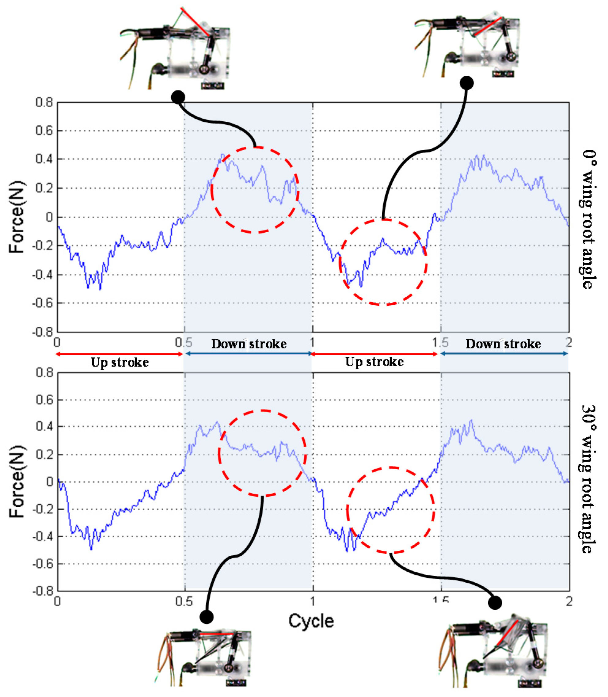
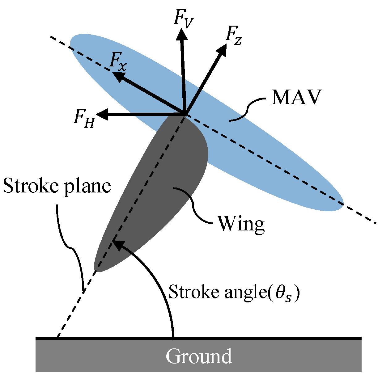
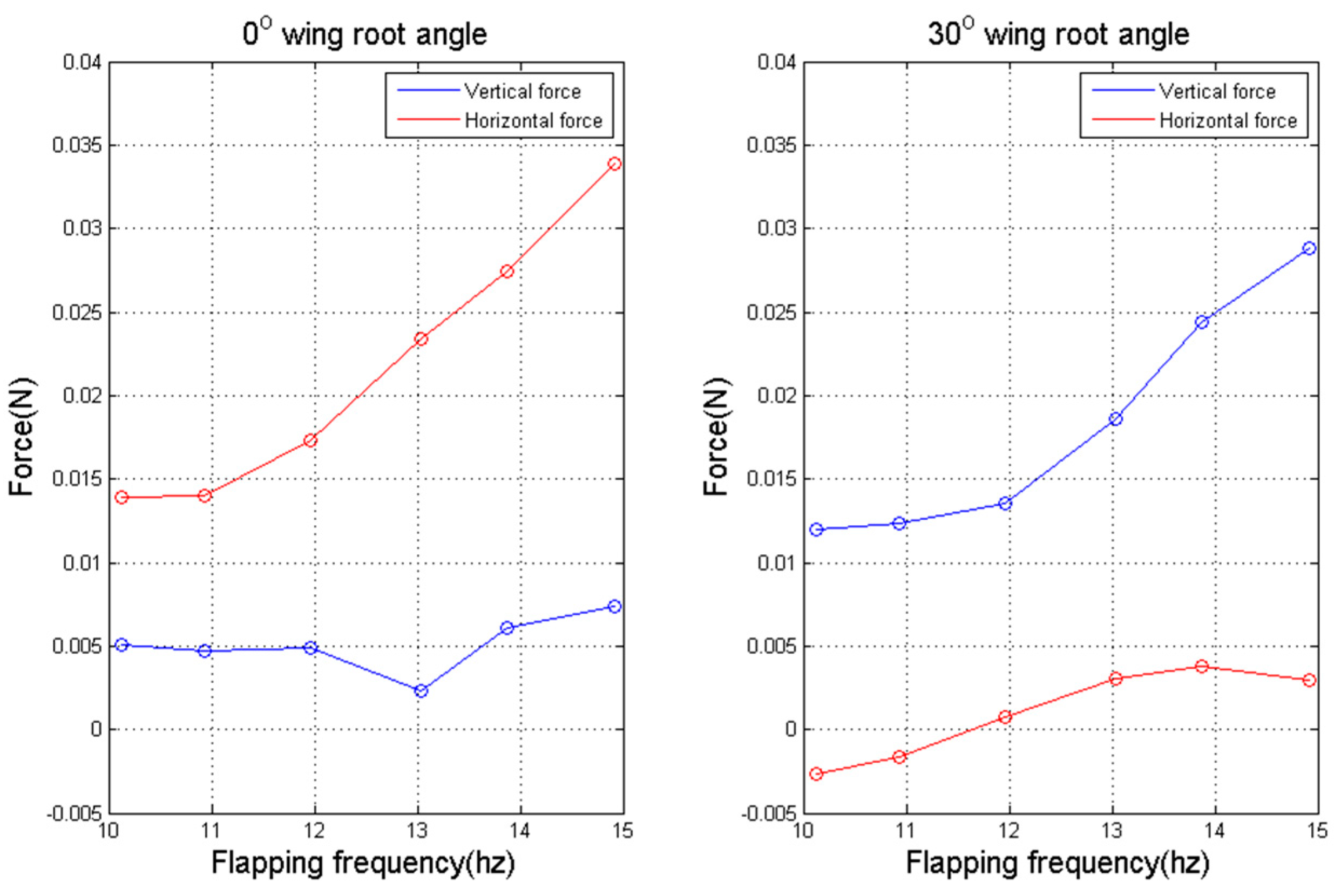
6.3.2. Force Direction Change with Respect to Wing Root Angle

Figure 23 shows the vertical and horizontal forces generated in the wing during flapping at a stroke angle of 60°. The vertical and horizontal forces were calculated by Equations (17) and (18), respectively. The graph on the left shows the force generated at a wing root angle of 0° and the graph on the right shows the force generated at a wing root angle of 30°. At a wing root angle of 0°, the horizontal force increased with increasing flapping frequency, and the vertical force is 0.005 N, which is lower than the horizontal force. This means that the MAV generates force in the appropriate direction for forward flight when it has a wing root angle of 0° at flapping. Comparison with a 0° wing root angle shows that the vertical force at a wing root angle of 30° increases with increasing flapping frequency, and the horizontal force has a value close to 0 N. Therefore, when MAV flaps with a wing root angle of 30°, the wing generates a force in the direction for hovering. Thus, the wing root angle is an important factor in determining the flight mode of the MAV, and the flight mode can be changed by changing the wing root angle.

7. Conclusions

In this study, we propose a mechanism to change the mean angle of attack of MAVs by rotating the wing roots. The links used in the flapping mechanism and the wing root rotation mechanism were optimized, and the graphs show the motion of the optimized mechanism. To confirm whether the proposed mechanism has stable hovering ability and can change flight mode without a posture change, a prototype incorporating the flapping mechanism and wing root rotation mechanism was fabricated, and the force generated by the MAV was measured. The prototype was designed using a ball-screw mechanism to independently control the wing root rotation mechanism and flapping mechanism. The measured force showed that the MAV with the wing root rotation mechanism can fly more stably when hovering and can change the flight mode by changing only the wing root angle. In the future, the wing root rotation mechanism is expected to fly more stably than the MAV with a lift-based system, and it will be possible to develop an MAV that mimics the interaction between the forewing and hindwing of an actual dragonfly.

Author Contributions

Supervision and Funding Acquisition, G.-H.Y.; Writing-Review & Editing, G.-H.Y.; Conceptualization, J.J.; Writing-Original Draft Preparation, J.J.; Design and Fabrication J.J.; Data acquisition and analysis, J.J.

Funding

This work was supported in part by the Korea Institute of Industrial Technology as under “Development of Soft Robotics Technology for Human-Robot Coexistence Care Robots (KITECH EO180026).”

Conflicts of Interest

The authors declare no conflict of interest.

References

  1. Wood, R.J. Design, fabrication, and analysis of a 3DOF, 3 cm flapping wing mav. In Proceedings of the 2007 International Conference on Intelligent Robots and Systems, San Diego, CA, USA, 29 October–2 November 2007; pp. 1576–1581. [Google Scholar]
  2. Keennon, M.; Klingebiel, K.; Won, H.; Andriukov, A. Development of the Nano Hummingbird: A tailless flapping wing micro air vehicle. In Proceedings of the 50th AIAA Aerospace Sciences Meeting, Nashville, TN, USA, 9–12 January 2012; p. 588. [Google Scholar]
  3. Phan, H.V.; Park, H.C. Generation of Control Moments in an Insect-link Tailless Flapping-wing Micro Air Vehicle by Changing the Stroke-plane Angle. J. Bionic Eng. 2016, 13, 449–457. [Google Scholar] [CrossRef]
  4. Rosen, M.H.; Pivain, G.L.; Sahai, R.; Jafferis, N.T.; Wood, R.J. Development of a 3.2 g Untethered Flapping-Wing Platform for Flight Energetics and Control Experiments. In Proceedings of the 2016 IEEE International Conference on Robotics and Automation (ICRA), Stockholm, Sweden, 16–21 May 2016; pp. 3227–3233. [Google Scholar]
  5. Ramezani, A.; Shi, X.; Chung, S.J.; Hutchinson, S. Bat Bot (B2), A Biologically Inspired Flying Machine. In Proceedings of the 2016 IEEE International Conference on Robotics and Automation (ICRA), Stockholm, Sweden, 16–21 May 2016; pp. 3219–3226. [Google Scholar]
  6. Hsiao, F.Y.; Yang, L.J.; Lin, S.H.; Lin, S.H.; Chen, C.L.; Shen, J.F. Autopilots for Ultra Lightweight Robotic Birds: Automatic Altitude Control and System integration of a Sub-10g Weight Flapping-Wing Micro Air Vehicle. IEEE Control Syst. Mag. 2012, 14, 35–48. [Google Scholar]
  7. Karásek, M.; Muijres, F.T.; Wagter, C.D.; Remes, B.D.W.; de Croon, G.C.H.E. A tailless aerial robotic flapper reveals that flies use torque coupling in rapid banked turns. Science 2018, 361, 1089–1094. [Google Scholar] [CrossRef] [PubMed]
  8. Alexander, D. Unusual phase relationships between the forewing and hindwings in flying dragonflies. J. Exp. Biol. 1984, 109, 379–383. [Google Scholar]
  9. Norberg, R. Hovering flight of the dragonfly: Aeschna juncea L. Kinematics and aerodynamics. Swim. Fly. Nat. 1975, 2, 763–780. [Google Scholar]
  10. Wang, J.K.; Sun, M. A computational study of the aerodynamics and forewing-hindwing interaction of a model dragonfly in forward flight. J. Exp. Biol. 2005, 208, 3785–3804. [Google Scholar] [CrossRef] [PubMed] [Green Version]
  11. Hu, Z.; Deng, X.Y. Aerodynamic interaction between forewing and hindwing of a hovering dragonfly. Acta Mech. Sin. 2014, 30, 787–799. [Google Scholar] [CrossRef]
  12. Usherwood, J.R.; Lehmann, F.O. Phasing of dragonfly wings can Improver aerodynamic efficiency by removing swirl. J. R. Soc. Interface 2008, 5, 1303–1307. [Google Scholar] [CrossRef] [PubMed]
  13. Wang, Z.J. Dissecting insect flight. Annu. Rev. Fluid Mech. 2005, 37, 183–210. [Google Scholar] [CrossRef]
  14. Wang, Z.J. The role of drag in insect hovering. J. Exp. Biol. 2004, 207, 4147–4155. [Google Scholar] [CrossRef] [PubMed] [Green Version]
  15. Vogel, S. Lift in Moving Fluids; Princeton University: Princeton, NJ, USA, 1996. [Google Scholar]
  16. Ellington, C.P. The aerodynamics of Hovering Insect Flight. III. Kinematics. Philos. Trans. R. Soc. Lond. B 1984, 305, 41–78. [Google Scholar] [CrossRef]
  17. Ellington, C.P. The Novel Aerodynamics of Insect Flight: Applications to Micro-air Vehicles. J. Exp. Biol. 1999, 202, 3439–3448. [Google Scholar] [PubMed]
  18. San, S.P.; Dickinson, M.H. The Control of Flight Force by a Flapping Wing: Lift and Drag Production. J. Exp. Biol. 2001, 204, 2607–2626. [Google Scholar]
  19. Dickinson, M.H. The Effects of Wing Rotation on Unsteady Aerodynamic Performance at Low Reynolds Numbers. J. Exp. Biol. 1994, 192, 179–206. [Google Scholar] [PubMed]
  20. Dickinson, M.H. Wing rotation and the Aerodynamic Basis of Insect Flight. Science 1999, 284, 1954–1960. [Google Scholar] [CrossRef] [PubMed]
  21. Bergou, A.J.; Xu, S.; Wang, J. Passive wing pitch reversal in insect flight. J. Fluid Mech. 2007, 591, 321–337. [Google Scholar] [CrossRef]
  22. Whitney, J.P.; Wood, R.J. Aerodynamics of passive rotation in flapping flight. J. Fluid Mech. 2010, 60, 197–220. [Google Scholar] [CrossRef]
  23. McIntosh, S.H.; Agrawal, S.K.; Khan, Z. Design of a Mechanism for Biaxial Rotation of a Wing for a Hovering Vehicle. IEEE/ASME Trans. Mechatron. 2006, 11, 145–153. [Google Scholar] [CrossRef]
  24. Fenelon, M.A.A.; Furukawa, T. Design of an active flapping wing mechanism and a micro aerial vehicle using a rotary actuator. Mech. Mach. Theory 2010, 45, 137–146. [Google Scholar] [CrossRef]
  25. Karásek, M.; Hua, A.; Nan, Y.; Lalami, M.; Preumont, A. Pitch and Roll Control Mechanism for a Hovering Flapping Wing MAV. Int. J. Micro Air Veh. 2014, 6, 253–264. [Google Scholar] [CrossRef] [Green Version]
  26. Nguyen, Q.V.; Park, H.C.; Goo, N.S.; Byun, D. Characteristics of a Beetle’s Free Flight and a Flapping-Wing system that Mimics Beetle Flight. J. Bionic Eng. 2010, 7, 77086. [Google Scholar] [CrossRef]
  27. Karásek, M. Robotic Hummingbird: Design of a Control Mechanism for a Hovering Flapping Wing Micro Air Vehicle. Ph.D. Thesis, Department of Mechanical, Engineering and Robotics, Delft University, Delft, The Netherlands, 2014. [Google Scholar]
  28. Wang, H.; Zeng, L.; Liu, H.; Yin, C. Measuring wing kinematics, flight trajectory and body attitude during forward flight and turning maneuvers in dragonflies. J. Exp. Biol. 2003, 206, 745–757. [Google Scholar] [CrossRef] [PubMed] [Green Version]
  29. Azuma, A.; Azuma, S.; Watanabe, I.; Furuta, T. Flight Mechanics of a Dragonfly. J. Exp. Biol. 1985, 116, 79–107. [Google Scholar]
  30. Okamoto, M.; Yasuda, K.; Azuma, A. Aerodynamic Characteristics of the Wings and Body of a Dragonfly. J. Exp. Biol. 1996, 199, 281–294. [Google Scholar] [PubMed]
  31. Hu, Z.; McCauley, R.; Schaeffer, S.; Deng, X. Aerodynamics of Dragonfly Flight and Robotic Design. In Proceedings of the 2009 IEEE International Conference on Robotics and Automation (ICRA), Kobe, Japan, May 12–17 May 2009; pp. 3061–3066. [Google Scholar]
  32. Koehler, C.; Lisang, Z.; Gaston, Z.; Wan, H.; Dong, H. 3D reconstruction and analysis of wing deformation in free-flying dragonflies. J. Exp. Biol. 2012, 215, 3018–3027. [Google Scholar] [CrossRef] [PubMed] [Green Version]
  33. Agrawal, A.; Agrawal, S.K. Design of Bio-inspired Flexible Wings for Flapping-Wing Micro-sized Air Vehicle Applications. Adv. Robot. 2009, 23, 979–1002. [Google Scholar] [CrossRef]
  34. Du, G.; Sun, M. Effects of wing deformation on aerodynamic forces in hovering hoverflies. J. Exp. Biol. 2010, 213, 2273–2283. [Google Scholar] [CrossRef] [PubMed] [Green Version]
  35. Pelletier, A.; Mueller, T.J. Low Reynolds Number Aerodynamics of Low-Aspect_Ratio, Thin/Flat/Cambered-Plat Wings. J. Aircr. 2000, 37, 825–832. [Google Scholar] [CrossRef]
  36. Caetano, J.V.; Percin, M.; van Oudheusden, B.W.; Remes, B.; de Wagter, C.; de Croon, G.C.H.E.; de Visser, C.C. Error Analysis and Assessment of Unsteady Forces Acting on a Flapping Wing Micro Air Vehicle: Free-Flight versus Wind Tunnel Experimental Methods. Bioinspir. Biomim. 2015, 10, 056004. [Google Scholar] [CrossRef] [PubMed]
Figure 1. Coordinate system of flapping motion.
Applsci 08 01868 g001
Figure 2. Stroke motion of a (a) lift-based system and (b) drag-based system.
Applsci 08 01868 g002
Figure 3. (a) Passive wing rotation mechanism using a loose wing membrane and (b) loosen membrane in moving wing.
Applsci 08 01868 g003
Figure 4. Range of angle of attack with respect to the wing root angle.
Applsci 08 01868 g004
Figure 5. Slide-crank mechanism with three-bar link.
Applsci 08 01868 g005
Figure 6. Schematic kinematics of wing root rotation mechanism.
Applsci 08 01868 g006
Figure 7. (a) Kinematics of input motion (slide motion) and output motion (wing root rotation). (b) Graph of relationship between θ r and d 2 to define d 2 with respect to desired θ r (30°).
Applsci 08 01868 g007
Figure 8. Limitation of spherical joint.
Applsci 08 01868 g008
Figure 9. Schematic kinematics of spatial four-bar link-based flapping mechanism.
Applsci 08 01868 g009
Figure 10. (a) Projected on the y-z plane; (b) projected on the x-z plane of flapping mechanism.
Applsci 08 01868 g010
Figure 11. Values of θ 2 , x , θ 2 , z , and θ 3 with respect to the crank angle.
Applsci 08 01868 g011
Figure 12. (a) Side view of the prototype design for the rotation mechanism; (b) front view of prototype design for the flapping mechanism.
Applsci 08 01868 g012
Figure 13. (a) Designed prototype and (b) front view of fabricated prototype.
Applsci 08 01868 g013
Figure 14. Experimental setup.
Applsci 08 01868 g014
Figure 15. Flowchart of force and image data.
Applsci 08 01868 g015
Figure 16. (a) Flapping amplitude image of prototype; (b) flapping amplitude comparison between designed and measured value.
Applsci 08 01868 g016
Figure 17. Angle of attack at each upstroke and downstroke at wing root angles of 0° and 30°.
Applsci 08 01868 g017
Figure 18. The measured angles of attack.
Applsci 08 01868 g018
Figure 19. (a) Measured F x and F z and (b) difference with respect to flapping frequency.
Applsci 08 01868 g019
Figure 20. Drag force comparison between 0° and 30° wing root angle at 15 Hz flapping frequency.
Applsci 08 01868 g020
Figure 21. Force direction at an inclined stroke angle.
Applsci 08 01868 g021
Figure 22. Horizontal force comparison between drag-based system and lift-based system at hovering.
Applsci 08 01868 g022
Figure 23. Vertical force and horizontal force with respect to flapping frequency at an inclined stroke angle.
Applsci 08 01868 g023
Table 1. Kinematics of dragonfly for experiment.
Angle of AttackStroke AmplitudeStroke Angle
Angle HoverForward−40°~40°60°
Down stroke75°45°
Up stroke15°45°
Mean angle of attack30°
Table 2. Design parameters of wing root rotation mechanism.
Design Parameters s 1 s 2 s 4 θ 1 d 2 , min
Value6 mm6 mm12.62 mm72.97°13 mm
Table 3. Value of design parameters of the flapping mechanism.
l 1 l 2 l 3 l 4 , x l 4 , z θ 2 , x θ 2 , z θ 3
6 mm26.8 mm9.331 mm−4.43 mm26.67 mm76.85°~103.1°79.46°~84.19°−40°~39.91°

