Abstract
In this study, to investigate the performance characteristics of a seawater ice-making device, using a scraped surface double tube evaporator, experiments were conducted under various operating conditions, including inlet temperature and flow rate of seawater, evaporating temperature, and scraper rotation speed. The main results are summarized as follows: (1) The section where stable ice making is possible, is determined by the inlet temperature and the flow rate range of seawater. By controlling the flow rate of seawater, the ice packing factor (IPF) of the device can be adjusted from 0.3 to 14.7%. (2) The IPF increases in cases where the evaporating temperature decreases linearly, until −13 °C. As the temperature of refrigerant that flows into the evaporator changes, the IPF is changed. Consideration is required for these connections. (3) The IPF increases when speeding up the scraper. The minimum rotating speed of the scraper was 350 rpm in these experiments. Optimum operating conditions for the seawater ice slurry maker are established through experiments. These results will be considered as important data for designing a slurry type seawater ice-making device.
1. Introduction
Low-temperature storage is essential for aquatic products because the freshness rapidly decreases immediately after the catch. The decline of aquatic products relates not only to quality, but also to consumers’ health, resulting in a large difference in the value of the product depending on the freshness [1]. In addition, in recent years, because of the enrichment of the public consciousness, there is a demand for fresher or even live catch [2,3]. Therefore, to meet future demands, it is important to improve the quality of the catch rather than the quantity.
However, it is difficult to install a suitable freezing device for each size of fishing vessel in Korea, because most of the fishing vessels are less than 30~100 tons [4]. Therefore, fishing and transport vessels are using crushed ice which is made of fresh water, and in a fishing area, the catches are mixed with the pre-loaded ice and stored in the fish storage hold. In this case, since crushed ice is used for the storage of the catch, there is a problem of osmotic pressure due to the difference in salt salinity with the catch, and can be damaging to the catch due to the large and sharp shapes of ice during storage and transportation. In addition, when mixed with seawater, ice is deposited at the top of the seawater due to the difference in density of seawater and ice, resulting in a temperature gradient in the storage. Due to the large shape of the crushed ice, air pockets occur when cooling small catches such as anchovies and shrimps, and the ice does not come in close contact with the catch, thereby interfering with the low-temperature maintenance of the catch. Because of the above reasons, using crushed freshwater ice has limitations in keeping the quality of the catch and maintaining the best quality of the catch. Therefore, there is a need for a new cooling method.
The ice slurry shown in Figure 1 is a solid–liquid two-phase fluid in which small ice particles are mixed with water or a low-concentration aqueous solution and is called ice slurry, snow ice, flow ice, sherbet ice and so on. Since the size of the ice particles is as small as a few micrometers, the contact area with the object to be cooled can be increased; therefore the cooling rate is fast, and the ice particles are mixed with the liquid so that it can be easily transferred to the general pump and piping. It also contains the latent heat of ice, so it has more than 80 times the amount of cold capacity compared to the same amount of water. The temperature of the ice slurry has the same freezing point as the liquid, and therefore a lower temperature can be obtained from the ice slurry than that of the fresh water by controlling the concentration of the aqueous solution.
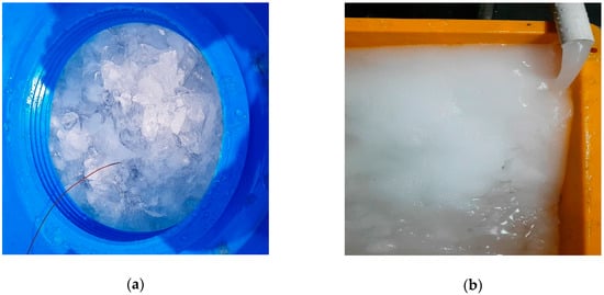
Figure 1.
Photograph of crushed ice and ice slurry: (a) Crushed freshwater ice; (b) Seawater ice slurry.
As described above, the slurry type ice-making device has been studied since the late 1990s [5,6,7,8]. Due to the advantages of the ice slurry, and the heat transfer characteristics of the ice-making device using brine without phase change, research on ice packing factor (IPF) measurement methods have been carried out. However, studies on the ice-making device with seawater for cooling of the catch and the performance characteristics of the ice-making device are insufficient. Traditional studies related to this study are as follows.
First, Lakhdar et al. [9] experimentally investigated the effect of different parameters on heat transfer in SSHE (Scraped Surface Heat Exchanger) where freezing of the water/ethanol mixture and aqueous sucrose solution occurs. Ethanol solutions were used as a secondary refrigerant on the outside of the ice maker. The internal heat transfer coefficient has been found to have the greatest effect on the rotational speed of the wing included in the SSHE.
Stamatiou et al. [10] showed the basic theory of ice slurry production and the practical use of two types of ice-makers, namely, scraped surface type and orbital rod type. The product was presented and reviewed. Recent research has concentrated on obtaining the heat transfer coefficient in an ice slurry maker, but due to the complex fluid flow and heat transfer resulting from forced convection, including phase change and agitation, the heat transfer correlation does not exist yet. Therefore, in order to compete with existing HVAC (Heating, Ventilation and air conditioning) and refrigeration technologies, the current ice slurry-making technology needs to be optimized for smaller, more efficient, and less costly processes by understanding basic crystal theories and heat transfer mechanisms.
Qin et al. [11] calculated the heat transfer coefficient in the SSHE heat exchanger during freezing of the aqueous sucrose solution and measured the amount of power required to rotate the scraper. As a secondary refrigerant, a solution of ethylene glycol was used. As a result, the heat transfer coefficient at the beginning of ice formation was 3 to 5 times larger than without phase change. When the ice growth started, the torque for driving the scraper continued to increase until the scraper stuck and stopped, and this was presented by numerical modeling.
Martı’nez et al. [12] compared the heat transfer phenomena during ice-making of a sodium chloride aqueous solution using plate-type SSHE according to the arrangement, speed and logarithmic temperature difference of the scraper. The heat transfer coefficient decreases as the logarithmic temperature difference increases, which is explained with the result of ice layer growth as the speed of the scraper slows down.
Park et al. [13] proposed an ice-maker in which a spiral scraper was inserted into a rotating type ice maker to scrape ice produced on the inside of a copper tube. The critical heat flux and the critical temperature at which it is possible to dehydrate the ice slurry continuously are collected through experiments and then modeled and verified.
Pamitran et al. [14] reported the characteristics of seawater ice formation using an evaporator including a wing type scraper and an orbital rod for fish cooling using seawater. The freezing point of seawater is lower than water because of its high salinity. The higher the salinity, the longer the time and the lower the temperature required for crystal nucleation. Therefore, when the salinity increases, the size of the ice decreases, and the enthalpy increases.
Jeong et al. [15] investigated the optimum ratio of the expansion valve and the optimum operating condition of the drum rotation speed in order to develop an automation system capable of high-efficiency operation of the sea ice maker using the drum type evaporator. The Coefficient of Performance (COP) increases and the superheat decreases with the increase of the opening. The ice output is not influenced by the increase of the opening. Also, the rotational speed of the evaporator drum does not have a significant effect on COP and superheat.
Although many research results have been reported on the heat transfer shape of various types of scraper type ice makers, the refrigerant used in the ice making is a secondary refrigerant without a phase change process, and therefore, it cannot be generally used due to its shape of the heat exchanger and the type of solution. In addition, data on the actual ice amount and the system according to the parameters affecting the heat transfer in the actual seawater application system are also insufficient. Therefore, the purpose of this paper is to provide basic data of the slurry type ice-making device using seawater by experimentally examining performance characteristics according to various conditions.
2. Ice Packing Factor of Ice Slurry with Seawater
Ice slurry is a liquid in which fine particles of ice are mixed. The ratio of the ice contained in the liquid, that is called the IPF, can be adjusted according to the purpose of use. It can be adjusted from 0 to 30% at the outlet of the manufacturing equipment and is up to 40% when using an ice storage tank, and is up to 80% if ice and liquid are separated. In particular, the use of ice slurry with seawater as the raw water in the fishery industry can provide the following advantages:
- It can be transferred to a pump and general piping.
- It has much cooling capacity.
- No air layer occurs due to small particles, and there is no damage to the catch due to the shape and weight of ice.
- Cooling speed is fast because of its wide heat transfer area.
- Since the ice is made using seawater, there is no difference in salinity between the fish and the catch.
- It is possible to cool to the optimum temperature and salt salinity suitable for the catch by controlling salinity and IPF.
This section briefly summarizes the overview of the slurry type seawater ice-making device and the basic information about the IPF.
2.1. IPF of Slurry Type Seawater Ice
2.1.1. Summary of IPF
The IPF is the ratio of the mass of ice to the mass of the total aqueous solution for an aqueous solution containing ice, and can be expressed as Equation (1).
IPF is a very important factor in dealing with high and low liquidity such as ice slurry with seawater, because the properties and characteristics of ice slurry vary according to the IPF and therefore its application is different.
2.1.2. Characteristics of Ice Slurry with Seawater According to IPF
In the slurry type seawater ice-making device, the ice is a crystal formation and is made from pure water that contains little salinity. For the above reason, when mixing seawater with freshwater ice, the salinity of the seawater decreases as the ice amount increases, but in the case of ice slurry made from seawater, as the IPF of the seawater ice increases, the salinity of the seawater increases. In addition, since the temperature of the ice slurry made from seawater is the same as the freezing point of the seawater, the temperature of the ice slurry made from seawater becomes lower as the IPF increases. Because the salinity of seawater, IPF, and the temperature of the ice slurry made from seawater are closely related, it is possible to adjust the initial salinity and IPF of the seawater to make an optimum temperature and salinity for maintaining the freshness of the catch. Table 1 shows the temperature and salinity [16] of the ice slurry made from seawater by the mixing ratio of common seawater and fresh water.

Table 1.
Freezing point and salinity according to mixing rate and ice packing factor (IPF) [16].
3. Experimental Apparatus and Method
3.1. Experimental Apparatus
3.1.1. Summary of Experimental Apparatus
Figure 2 shows the experimental setup of the seawater ice-making device using the scraped surfaced. Figure 3 shows an experimental apparatus actually manufactured. As in Figure 2, the device is largely divided into refrigerant lines, cooling water lines, and seawater lines. The refrigerant side is composed of an inverter scroll compressor, oil separator, condenser, receiver, filter dryer, sight glass, mass flow meter, and scraped surface double tube evaporator.
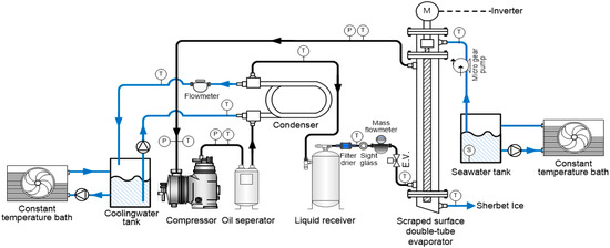
Figure 2.
Schematic diagram of an experiment apparatus.
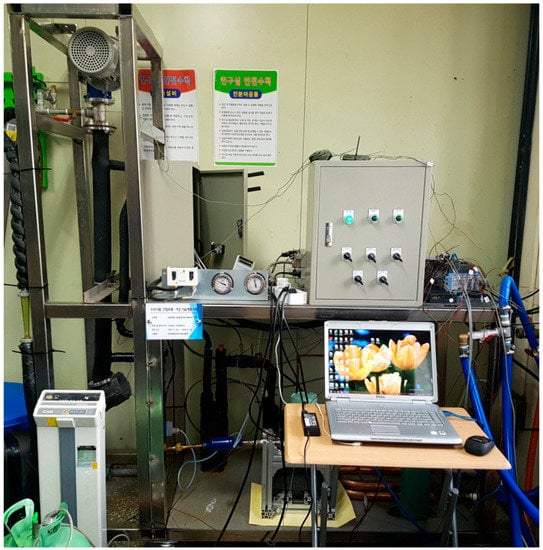
Figure 3.
Photograph of an experiment apparatus.
The high-temperature and high-pressure refrigerant discharged from the compressor are condensed and cooled through a heat exchange with coolant in the condenser, and then it flows into the liquid receiver in the liquid phase. After the receiver, the liquefied refrigerant passes through the filter dryer, the sight glass, and the mass flow meter and the expansion valve. The refrigerant that has passed through the expansion valve flows from the lower portion of the external pipe of the scraped surface double tube evaporator, cools the seawater flowing into the inner pipe, evaporates and flows out to the upper portion of the evaporator. The refrigerant flows to the compressor and it re-circulates.
A scraper is inserted into the inner pipe of the evaporator, and it is rotated through the motor at the upper end and scrapes the ice generated from the inner wall to form ice slurry. At this time, the number of revolutions of the scraper were designed to be controlled by the inverter connected to the motor with the scraper.
The compressor uses an inverter compressor to adjust the rotational speed according to the set evaporation pressure to maintain a constant evaporation pressure and a water-cooled double tube condenser using corrosion-resistant titanium material is used. The electronic expansion valve controls the refrigerant flow rate by adjusting the opening degree of the expansion valve from 0 to 500 steps so that the superheat degree of the evaporator outlet is kept constant. Since Freon refrigerant is used, an oil separator is installed to facilitate the recovery of oil in the compressor, and for the stability of the system, the receiver and the filter dryer at the outlet of the condenser are installed.
The coolant enters the condenser from the coolant tank through the pump, condenses the refrigerant, passes through the flow meter, and returns to the coolant tank. The coolant tank is maintained at a constant temperature through a thermostatic bath. The seawater flowing into the evaporator is also maintained at a constant temperature through a thermostatic bath. Then through a micro-motion gear pump, which can be adjusted to 0.01 LPM, the seawater flows into the evaporator at a constant flow rate and is discharged from the bottom of the evaporator in the form of ice slurry with seawater.
As shown in Figure 2, a pressure sensor and T-type thermocouple are installed at the inlet and outlet of the main equipment such as the compressor, condenser, expansion valve, and evaporator to measure the temperature and pressure of the refrigerant. The temperature of seawater and coolant is precisely measured by averaging each three group of T-type thermocouples inserted in tubes and measured up to two decimal places.
The flow rates of the refrigerant and coolant are measured through a mass flow meter and a water flow meter, respectively. The power consumed by the compressor is measured using a power meter, and the data logger (YOKOGAWA/GM90PS) is used for the measurement and recording of all data. The accuracy of measuring instruments is shown in Table 2.
Table 2.
Accuracy of measuring instruments.
3.1.2. Structure of a Scraped Surface Double Tube Evaporator
In this study, a scraped surface double tube evaporator with a screw type scraper inserted inside the scraped surface double tube heat exchanger inner tube is used.
The scraped surface double tube evaporator consists mainly of a double tube heat exchanger, scraper, motor for rotating the scraper and a speed reducer. The structure of the double tube heat exchanger is shown in Figure 4. Since seawater is a corrosive fluid, the inner pipe through which seawater flows is made of titanium, and the outer surface where refrigerant flows is made of copper pipe. An aluminum heat transfer pin was inserted between the outer tube and the inner tube to support the outer tube and widen the heat transfer area to promote heat transfer. The outer diameter of the inner titanium tube is 31.75 mm and the outer diameter of the copper tube is 47.8 mm. The total length of double tube heat exchanger is 1000 mm and the effective length of heat transfer is 800 mm.
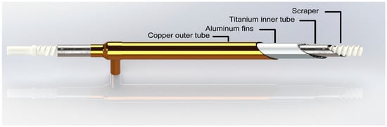
Figure 4.
Schematic diagram of the double tube evaporator using scraper.
The double tube heat exchanger is arranged vertically and the low-temperature refrigerant flows from the bottom to the upper side of the semi-flooded type heat exchanger, which has a small channel between the copper tube and the aluminum pin to improve the heat exchange. The screw type scraper which is inserted into the titanium tube is made of engineering plastic (POM). The length of the scraper is 1200 mm, the outside diameter is 29 mm, and the inside diameter is 0.5 mm. The scraper is made in a spiral shape to facilitate the transfer of ice from the upper part to the lower part and scrapes off the ice layer formed on the wall of the tube through the rotation and discharges it in the form of ice slurry with seawater.
According to Lakhdar et al. [9], the optimum rotation speed is 300 rpm when the outer diameter of the rotating body for ice making is 38 mm. To maintain the same line speed as proposed in this study, the rotating speed of the scraper should be about 400 rpm. To satisfy this requirement, a speed reducer is attached to the motor. The motor is connected to the inverter so that the speed of the scraper can be adjusted from 260 to 440 rpm by adjusting the frequency of the inverter.
3.2. Experiment Method and Conditions
This experiment was carried out in the following order:
- Confirm the salinity of the seawater using a salinity meter.
- Operate the chiller and heat pump connected to the cooling water and seawater tank and adjust them to the set temperature according to the experimental conditions.
- Start the pump so that the cooling water and the seawater flow through the condenser and the evaporator, and operate the motor connected to the scraper.
- Supply power to the unit and enter the set value for superheating on the electronic expansion valve. After the set evaporation pressure is confirmed by the compressor controller, the compressor starts to operate. When the system operates, start the measurements using the measuring instruments.
- If the system is in a steady state (assume that the system is in a steady state if the temperature measurement variation is within ±0.5 °C, the pressure measurement variation is within ±10 kPa, and the mass flow rate variation is within 0.05 kg/min for 20 min) the temperature and pressure of the refrigerant, the mass flow rate, the inlet and outlet temperatures of the cooling water and seawater, and the power consumption of the compressor are recorded for 30 min using the equipment.
Table 3 shows the experimental conditions for the study.
Table 3.
Experimental conditions.
The refrigerant is R-22 and the set of superheat is maintained at 6 °C to prevent liquid compression in the compressor. The average surface temperature of the seawater flowing into the evaporator is set to 10~27 °C. This is because the temperature of seawater in the East Sea of Korea, the West Sea and the South Sea in Korea is 27 °C in summer and 10 °C in winter. The temperature of the coolant supplied to the condenser is 27 °C in the case of a domestic navigation ship according to the HVAC Design Guideline [17] for marine vessels. In spite of it being same seawater, the difference between the temperature of seawater used as the coolant and the temperature of seawater flowing into the evaporator is required for precooling the seawater flowing into the evaporator in order to retain the necessary IPF at the outlet of the icemaker. The evaporation temperature is varied from −8 °C to −15 °C in order to investigate the ice making characteristics according to the evaporation temperature.
3.3. Data Reduction
The thermal properties of seawater used in this study are calculated by the data presented by K.G Nayar et al. [18]
There are various methods of IPF calculation. However, in this study, the flow rate is small, and thus the piping of the mass flowmeter tends to clog and the error of the measured value tends to increase. So instead of the density measurement method, the temperature of the ice slurry with seawater is measured:
Equation (2) is the IPF relation using the salinity before and after icebreaking proposed by M’elinder et al. [19] Sf is the salinity of the seawater after deicing, and Si is the salinity of the seawater before deicing. The temperature of the ice slurry with seawater is the same as the freezing point in the seawater part, the freezing point relation [20] according to the salinity as in Equation (3), IPF can be calculated.
Tfre represents the freezing point (°C) of seawater, S represents the salinity of seawater (%), and P represents pressure (desibar).
The cooling capacity from the evaporator can be calculated as the sum of the heat exchange amounts of the latent heat part and the sensible heat part using the IPF as shown in Equation (4).
Qeva is the amount of cooling capacity from the evaporator, and Ti, Tf, and Tfre are the inlet temperature, outlet temperature, and freezing point of seawater respectively. Cp,sea and Cp,ice refers to the specific heat of seawater and ice, and L is the latent heat of ice.
4. Results and Discussion
The purpose of this paper is to provide basic data for the slurry type seawater ice-making device for sea and offshore fishing boats. This study, ‘slurry type seawater ice-making device using scraped surface double tube evaporator’, presents the optimal operating conditions of the ice maker under various conditions and provides the basic design data of the slurry type seawater ice-making device for fishing vessels.
For this, the experiments were carried out to analyze the temperature, IPF, and cooling capacity of the ice slurry made of seawater with varying inlet temperature, flow rate of seawater, evaporation temperature and scraper speed. The uncertainty of the experimental data under the nominal conditions is shown in Table 4 through Moffat’s equation [21].
Table 4.
Parameters and estimated uncertainties.
4.1. Influence of Seawater Flow Rate and Temperature
The effects of seawater on the ice making performance and performance characteristics of the slurry type seawater ice-making device were investigated when the seawater flow rate varied from 0.75 LPM to 1.25 LPM by 0.25 LPM depending on the nominal conditions. Depending on the inlet temperature and flow rate of the seawater, the ice cannot be de-iced or the flow rate is low and the device cannot be operated stably due to the adherence of ice in the tube and it was excluded in the graph.
Figure 5 shows the effect of the seawater flow rate and inlet temperature on the temperature of the ice slurry. The temperature of the ice slurry changed from −2.07 °C to −1.76 °C depending on the inlet temperature and flow rate of seawater.
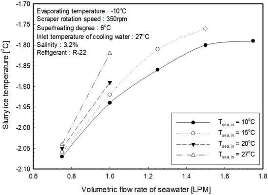
Figure 5.
Influence of seawater flow rate on temperature of ice slurry for inlet temperature of seawater.
The outlet temperature of the ice slurry decreases with respect to the inlet temperature of the seawater entering the evaporator. As the flow rate decreases, the outlet temperature of the ice slurry decreases. This is thought to be because the heat capacity of the seawater in the evaporator is reduced and the amount of heat required for ice-making is also reduced, resulting in higher IPF and an increase in the salinity of the outlet.
When the inlet flow rate of the ice generator is lowered to 0.8 LPM, the temperature of the water at the inlet of the ice generator does not significantly affect the temperature of the slurry ice. Therefore, if the inlet temperature of the seawater is high, it is possible to reduce the inlet flow rate for lower the slurry ice temperature. If the ice generator inlet temperature is high, there is an area where icing cannot be done above a certain flow rate. Therefore, it can be seen that appropriate flow control is required according to the inlet temperature of the seawater. When the inlet temperature of the seawater is below 10 °C, it is possible to make ice in the whole flow range. It can be confirmed that it is necessary to pre-cool the inlet temperature of the sea water to 10 °C or lower for stable deicing regardless of the flow rate.
Figure 6 shows the IPF according to the flow rate and inlet temperature of seawater. The IPF calculated from the temperature of the ice slurry at the outlet of the evaporator shows a larger value as the inlet temperature of the seawater and the flow rate is lower. When the inlet temperature of seawater is 10 °C, the seawater flow rate decreased from 14.7% to 0.3% as the seawater flow increased from 0.75 LPM to 0.25 LPM. Also, it can be seen that the higher the inlet temperature, the greater the decrease in IPF with increasing flow rate. It is considered that the IPF is decreased at high temperature and high flow rate, because the amount of heat needed for cooling to the temperature required for ice making increases, due to the high temperature of seawater and the large amount of flow.
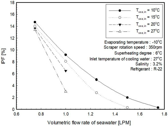
Figure 6.
Influence of seawater flow rate on IPF for inlet temperature of seawater.
Figure 7 shows the cooling capacity in the evaporator depending on the inlet temperature and flow rate of seawater. It can be seen that the cooling capacity in the evaporator tends to increase as the heat exchange rate in the evaporator increases. This occurs as the temperature difference between the evaporation temperature and the seawater increases with the rise of the inlet temperature of the seawater. In the case of cooling capacity, the flow rate of seawater is constant at 0.75 LPM, it increases from 1.215 kW to 2.025 kW with increasing temperature. When the inlet temperature of seawater is fixed at 10 °C, it increases from 1.215 k to 1.430 kW with respect to the flow rate.
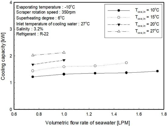
Figure 7.
Influence of seawater flow rate on cooling capacity for inlet temperature of seawater.
4.2. Influence of Evaporation Temperature
In order to understand the effect of evaporation temperature on the performance of the ice maker, the ice making characteristics and the performance characteristics of the scraper type slurry type seawater ice-making device were evaluated by varying the evaporation temperature from −8 °C to −15 °C.
Figure 8 shows the temperature of the ice slurry with seawater according to the evaporation temperature of the refrigerant. Figure 9 shows the IPF calculated from the initial salinity of seawater and the temperature of the ice slurry with seawater at the outlet of the evaporator measured above.
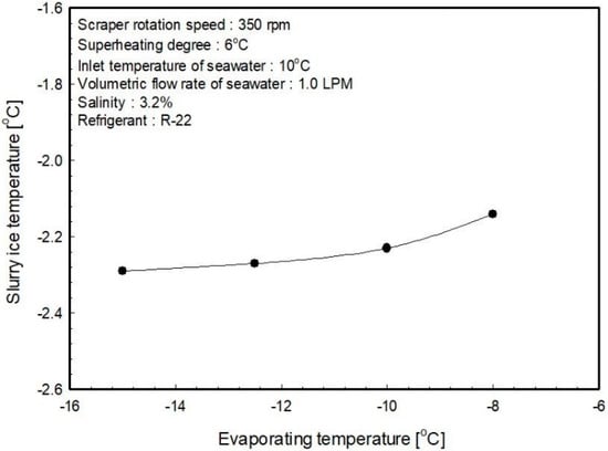
Figure 8.
Temperature of ice slurry with seawater according to evaporating temperature.
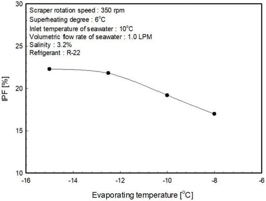
Figure 9.
IPF with respect to evaporating temperature.
As seen from Figure 8, the temperature of the ice slurry with seawater shows a tendency to decrease as the evaporation temperature decreases and changes from −2.29 °C to −2.14 °C depending on the evaporation temperature. Figure 9 shows the IPF of the ice generator according to the evaporation temperature. The IPF is increased from 6.9% to 12.7~19.6% according to the decrease of the evaporator temperature. It appears that the IPF and the refrigerant evaporation temperature are closely related, and the IPF is linearly increased as the evaporation temperature of the refrigerant is decreased. This is because the temperature difference between the two fluids in the evaporator increases as the evaporation temperature of the refrigerant decreases and cooling capacity in the evaporator increases. As the evaporation temperature decreases, the IPF tends to increase and it increases linearly to the evaporation temperature of −13 °C. However, at the lower temperatures, there is an inflection point where the increase rate of the IPF gradually changes. Therefore, in this system, lowering the evaporation temperature to below −13 °C seems to have advantage for increasing IPF. When the evaporation temperature is kept under −13 °C, the seawater flowing down the wall of the tube increases the adhesion with the tube wall, and the seawater ice rises by the shear rather than slip off the tube wall. So it is considered that the ice remaining on the surface acts as heat resistance and the rate of increase of the ice-making amount becomes gradual.
Figure 10 indicates the cooling capacity in the evaporator according to the evaporation temperature. As the evaporation temperature decreases from −8 °C to −15 °C, cooling capacity increases to 1.13~1.418 kW. The reason why the cooling capacity increases as the evaporation temperature decreases is because the temperature difference between the two fluids in the evaporator becomes larger as the evaporation temperature of the refrigerant decreases, as described above.
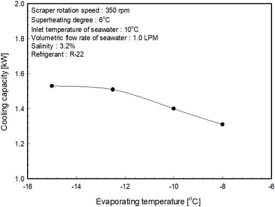
Figure 10.
Cooling capacity with respect to evaporating temperature.
4.3. Influence of Scraper Rotating Speed
The rotation of the scraper makes turbulence and vortexes possible to easily generate nuclei for phase change and it is closely related to the amount of heat transfer and IPF since it determines the time for ice to grow on the inner tube wall. As mentioned above, studies on the heat transfer according to the number of revolutions have been carried out for various scraper types, but the device using the double tube evaporator in this study using seawater requires experimental study. Through this experiment, the effects of IPF and cooling capacity on the scraper rotational speed were determined.
Figure 11 shows the influence of the temperature of the ice slurry with seawater changing the scraper rotating speeds with respect to the seawater flow rate under nominal conditions. Figure 12 is a graph showing IPF calculated from the initial salinity of seawater and the temperature of the ice slurry with seawater. As the number of scraper rotations increases, the temperature of the ice slurry with seawater decreases slightly and the IPF increases. In the case of seawater flow rate of 0.75 LPM, the IPF increases by 13% to 15%, while the seawater flow rate of 1.25 LPM increases by 4.5% to 5.0%.
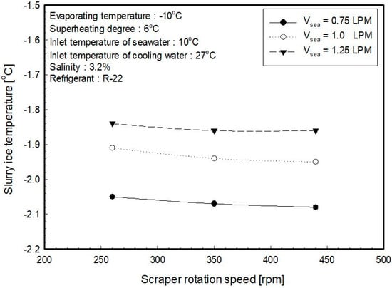
Figure 11.
Temperature of ice slurry with seawater according to scraper rotation speed.
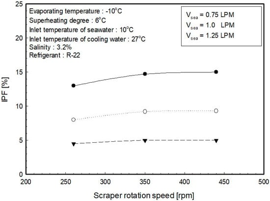
Figure 12.
IPF with respect to scraper rotation speed.
Figure 13 shows the cooling capacity in the evaporator as the number of revolutions of the scraper increases. As the flow rate of seawater flowing into the evaporator increases, the cooling capacity increases. As the number of revolutions of the scraper increases, the cooling capacity increases. Also, while the flow rate of the seawater flowing into the evaporator is 0.75 LPM, the cooling capacity varies from 1.143 kW to 2.227 kW, while the flow rate is 1.316 kW to 1.350 kW at 1.25 LPM, which is about twice as much. It was confirmed that as the flow rate decreases, the cooling capacity increment range becomes larger as with the scraper rotation speed. In Park et al. [14], with penetration theory, the heat transfer phenomenon in the scraper type heat exchanger is mainly influenced by the transient state conductivity newly formed in the tube wall by the scraper rotation, and increased heat transfer due to increased fluid film formation. As the same result of this experiment, as the rotating speed increases, the rotation Reynold’s number also increases, thus turbulence is promoted and the fluid film formation is increased and the ice nucleus crystal is increased. Consequently, the heat transfer coefficient is increased, the thickness of the ice layer formed on the inner wall of the tube is thinned, and the conduction heat resistance is decreased, and therefore, the heat transfer is improved. The ice generator used in this experimental system shows an increase tendency in the cooling capacity up to 350 rpm at the scraper rotation and over the 350 rpm, the increase rate of cooling capacity becomes gradually decreases. Therefore, it is found that the rotating speed of the scraper must be maintained at a minimum of 350 rpm when designing an ice maker using the ice generator. If the rpm of the scraper is increased, the amount of ice is also increased, but the power required for rotating the scraper also increases, so that the operation energy is increased. Therefore, the performance of the entire system may be reduced, so it is preferable to maintain the rotation speed at 350 to 400 rpm.
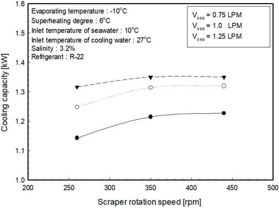
Figure 13.
Cooling capacity with respect to scraper rotation speed.
If the flow rate of the seawater into the ice generator is large, the effect on the cooling capacity with respect to the rotating speed of the scraper is reduced. It seems that as the flow rate increases, the IPF ratio decreases and the influence of increase of heat transfer due to the rotating force of the scraper becomes insignificant. And when the flow rate decreases, the thermal conductivity at the tube surface is dominantly influenced by the rotating force of the scraper as the IPF ratio increases.
5. Conclusions
In this study, a scraped surface double tube evaporator was applied as a basic experimental stage for practical application of a slurry type seawater ice-making device applicable to sea and offshore fishing vessels, and was experimented with, under various operating conditions of an ice making device, respectively. The main results obtained in this study are summarized as follows:
- The area where ice can be stably determined depends on the inlet temperature and flow range of the seawater. To increase the IPF, it is necessary to preheat the seawater under 10 °C and flow it into an evaporator.
- The evaporation temperature is closely related to the cooling capacity and IPF, and the evaporation temperature should be lowered to increase the IPF. In this paper until −13 °C, the IPF increases linearly.
- As the number of scraper rotations increases from 260 to 450 rpm, the cooling capacity and IPF increases. The smaller the flow rate of the seawater flowing into the evaporator, the greater the influence of increasing the number of scraper rotations. It is necessary to maintain the rotation speed of scraper over 350 rpm.
Based on the above results, the basic test results of the slurry type seawater ice-making device using the scraped surface double tube evaporator were obtained. It was confirmed that the temperature of the ice slurry and the IPF can be controlled at the end of the evaporator by adjusting the operating conditions.
Author Contributions
Conceptualization, C.-H.S. and J.-I.Y.; methodology, K.-H.C.; formal analysis, H.-K.L.; investigation, H.-K.L. and M.-J.J.; data curation, K.-S.L. and J.-H.L.; writing—original draft preparation, H.-K.L. and M.-J.J.; writing—review and editing, C.-H.S.; supervision, J.-I.Y.; project administration, C.-G.M. and M.-J.J.
Funding
This research received no external funding.
Acknowledgments
This research was a part of the project titled “Development of sherbet type ice-making device using sea water”, funded by the Ministry of Oceans and Fisheries, Korea., and was part of Hyun-Kyung Lee´s Master´s thesis on performance characteristic of seawater ice slurry making device with a scraped surface double tube evaporator.
Conflicts of Interest
The authors declare no conflict of interest.
References
- Kang, J.H.; Jang, H.S. A Study on the Current Status and Improvement of Post-Harvest Management in Fisheries; Research Report for Korea Maritime Institute: Busan, Korea, 2010; Volume 12. [Google Scholar]
- Choi, S.K.; Peck, J.H.; Hong, H.K.; Kang, C.D. Ice Slurry Formation Using a Sea Water with Additives; Society of Air-Conditioning and Refrigerating Engineers of Korea: Seoul, Korea, 2004; Volume 6, pp. 424–429. [Google Scholar]
- Joo, M.B.; Lee, H.D. Problems with the Current Cold Chain System and Measures for Improvement; Research Report for Korea; Maritime Institute: Busan, Korea, 2008; Volume 12. [Google Scholar]
- Kim, S.K. A Study on the Development of Ice-Making Device for the Offshore Fishing Boats Using Seawater; Ministry of Oceans and Fisheries of Korea: Seoul, Korea, 2010; Volume 11.
- Kauffeld, M.; Kawaji, M.; Egolf, P.W. Handbook on Ice Slurries—Fundamentals and Engineering; International Institute of Refrigeration: Paris, France, 2005. [Google Scholar]
- Bellas, I.; Tassou, S.A. Present and future applications of ice slurries. Int. J. Refrig. 2005, 28, 115–121. [Google Scholar] [CrossRef]
- Fukusako, S.; Kozawa, Y.; Yamada, M. Research and Development Activities on Ice Slurries in Japan; Second IIR Workshop on Ice Slurries; IIR Ice Slurry Workshops: Paris, France, 1999; pp. 83–105. [Google Scholar]
- Russell, A.B.; Cheney, P.E.; Wantling, S.D. Influence of freezing conditions on ice crystallisation in ice cream. Int. J. Food Eng. 1999, 39, 179–191. [Google Scholar] [CrossRef]
- Lakhdar, M.B.; Cerecero, R.; Alvarez, G.; Guilpart, J.; Flick, D.; Lallemand, A. Heat transfer with freezing in a scraped surface heat exchanger. Appl. Therm. Eng. 2005, 25, 45–60. [Google Scholar] [CrossRef]
- Stamatiou, E.; Meewisse, J.W.; Kawaji, M. Ice slurry generation involving moving parts. Int. J. Refrig. 2005, 28, 60–72. [Google Scholar] [CrossRef]
- Qin, F.; Chen, X.D.; Ramachandra, S.; Free, K. Heat transfer and power consumption in a scraped-surface heat exchanger while freezing aqueous solutions. Sep. Purif. Technol. 2006, 48, 150–158. [Google Scholar] [CrossRef]
- Martínez, D.S.; Solano, J.P.; Illán, F.; Viedma, A. Analysis of heat transfer phenomena during ice slurry production in scraped surface plate heat exchangers. Int. J. Refrig 2014, 48, 221–231. [Google Scholar] [CrossRef]
- Park, G.W.; Moon, I.H.; Cho, S.J.; Min, M.K. Study on the Ice Making Characteristics of Ice Slurry Maker Using Scraper; Society of Air-Conditioning and Refrigerating Engineers of Korea: Seoul, Korea, 2000; pp. 1109–1114. [Google Scholar]
- Pamitran, A.S.; Ardiansyah, H.D.; Novvili, M. Characteristics of sea-water ice slurry for cooling of fish. Appl. Mech. Mater. 2013, 388, 123–127. [Google Scholar] [CrossRef]
- Joo, W.J.; Byun, J.Y.; Jeong, T.Y.; Jeong, S.K. Performance Characteristics of a Seawater Ice Machine according to Opening Angle Variation of Electronic Expansion Valve. Korean Soc. Power Syst. Eng. 2009, 6, 337–342. [Google Scholar]
- Uno, M. Utilization of ice slurry in fishing boats. Mar. Fish. Eng. Jpn. 2008, 78, 40–45. [Google Scholar]
- Yoon, J.I.; Lee, H.S.; Choi, J.H. Basic planning of ship HVAC. J. Korean Soc. Mar. Eng. 2008, 32, 1110–1115. [Google Scholar]
- Nayar, K.G.; Sharqawy, M.H.; Banchik, L.D.; Lienhard, J.H. Thermophysical properties of seawater: A review and new correlations that include pressure dependence. Desalination 2016, 390, 1–24. [Google Scholar] [CrossRef]
- Melinder, A.; Granryd, E. Using property values of aqueous solutions and ice to estimate ice concentrations and enthalpies of ice slurries. Int. J. Refrig. 2005, 28, 13–19. [Google Scholar] [CrossRef]
- Fofonoff, N.P.; Millard, R.C., Jr. Algorithms for Computation of Fundamental Properties of Seawater; UNESCO Technical Papers in Marine Science; UNESCO: Paris, France, 1983; Volume 1–55. [Google Scholar]
- Moffat, R.J. Describing the uncertainties in experimental results. Exp. Therm. Fluid Sci. 1988, 1, 3–17. [Google Scholar] [CrossRef]


© 2018 by the authors. Licensee MDPI, Basel, Switzerland. This article is an open access article distributed under the terms and conditions of the Creative Commons Attribution (CC BY) license (http://creativecommons.org/licenses/by/4.0/).