Article

Three-Dimensional Nanofluid Flow with Heat and Mass Transfer Analysis over a Linear Stretching Surface with Convective Boundary Conditions

1
Department of Applied Mathematics, School of Science, Northwestern Polytechnical University, Dongxiang Road, Chang’an District, Xi’an 710129, China
2
Department of Mathematics, Abdul Wali Khan University, Mardan 23200, Pakistan
3
Department of Mathematics, Qurtuba University of Science and Information Technology Peshawar, Peshawar 25000, Pakistan
4
Department of Mathematics, Kohat University of Science and technology, Kohat 26000, Pakistan
*
Author to whom correspondence should be addressed.
Appl. Sci. 2018, 8(11), 2244; https://doi.org/10.3390/app8112244
Submission received: 23 October 2018 / Revised: 7 November 2018 / Accepted: 10 November 2018 / Published: 14 November 2018
(This article belongs to the Section Nanotechnology and Applied Nanosciences)

Abstract

:
In this study, we analyzed the three-dimensional flow of Williamson (pseudoplastic) fluids upon a linear porous stretching sheet. The thermal radiation impact was taken into account. The transformed non-linear equations were solved by the homotopy analysis method (HAM). The influence of the embedded parameters tretching parameter, Williamson parameter, porosity parameter, thermal radiation parameter, thermophoresis parameter, Brownian motion parameter, Prandtl number and Biot number are presented on velocity, temperature and concentration functions in the graphs and explained in detail. The velocity function along the x-direction reduces with the impact of the stretching, porosity and Williamson parameters. Velocity along the y-direction increases with the stretching parameter, while it reduces with the porosity and Williamson parameters. The effect of Skin friction, heat transfer and mass transfer are shown numerically. The numerical values of surface drag force and the impact of different parameters are calculated and it is observed that increasing the stretching parameter and the porosity parameter reduces the surface drag force, while increasing the Williamson parameter augments the surface drag force. Higher values of the stretching parameter, the Prandtl number and the radiation parameter enhance the heat transfer rate, while the augmented value of the thermophoresis and Brownian motion parameters reduces the heat transfer rate, where higher values of the stretching parameter, thermophoresis and Brownian motion parameters enhance the mass transfer rate.

1. Introduction

The non-Newtonian fluids have many applications in the field of fluid mechanics. For instance, geophysics, chemical industries, biological sciences and petroleum industries are some common applications in various industries. Due to these applications, research in the area of non-Newtonian fluids has received attention. Such flows appear in food processing, plastic manufacturing, polymer processing, biological fluids, ice and magma flows. Cord depiction, extrusion and copper spiraling are significant aspects of fluid flow upon a stretching surface. There are various studies that examined fluid flow over a stretching surface in two dimensions since the works of Sakadais and Crane [1,2]. In recent times, researchers drew attention to the field by studying fluid flow over a stretching surface in three dimensions (3-D). In 1929, Williamson [3] presented the theory of pseudo plastic fluids and found the practical significance of these fluids. Using the homotopy perturbation technique, the steady and laminar flow past a surface in three dimensions was presented by Ariel [4]. Using the Adomian decomposition method, the magnetohydrodynamic and boundary layer flow of Casson fluid past an exponentially shrinking sheet has been analyzed by Nadeem et al. [5]. In another article, Nadeem et al. [6] analytically probed the two-dimensional peristaltic flow of the Williamson model. The analytical solution of an incompressible micro polar fluid over an extending sheet has been analyzed by Pop et al. [7]. The analysis of viscous fluid flow in 3-D, past over extending surface, has been investigated by Sakiadis [8]. The two cases of heat transfer for recommended heat flux, and surface temperature with unsteady fluid flow over a continuous moving surface temperature, have been investigated by Tsou et al. [9]. They concluded that the velocity escalates with the escalation of the stretching parameter. Recently, premeditated three-dimensional Williamson fluid flow past a stretching surface has been studied by Malik et al. [10]. The process of blowing and suction combined with heat and mass transference rate past a stretching sheet has been introduced by Gupta and Gupta [11]. They extended the work of Erickson et al. [12] by replacing the constant surface speed with the linear surface speed. Aziz [13] perceived the heat radiation effect by studying the flow on an unsteady stretched sheet. In the presence of a porous medium, the impact of thermal radiation on a vertically stretched surface was studied by Mukhopadyay [14]. Shateyi and Motsa [15] numerically studied the changes in mass transfer and concentration rates over a horizontal stretched sheet. The effect of heat and momentum of incompressible fluid flow past a linear stretched surface has been investigated by Aziz [16]. The viscous fluid flow over a non-linear stretching surface under the impact of thermal radiation has been analyzed by Cortell [17]. In the case of uniform and non-uniform heat fluxes, the numerical study of heat transfer has been analyzed by Ishak et al. [18]. They claimed that the non-Newtonian model (Micro polar fluid) has a higher coefficient of convective heat transfer than viscous fluid flow. Eyring−Powell fluid flow under the impact of thermal radiation over a porous medium was investigated by Dawar et al. [19]. Magnetohydrodynamic (MHD) flow carbon nanotubes Casson nanofluid in rotating channels was studied by Dawar et al. [20]. Analytically-studied MHD Jeffery fluid under the impact of thermal radiation was studied by Abro et al. [21]. The recent analysis by Sheikholeslami on nanofluids can be seen in [22,23,24]. The recent relevant investigation on Casson fluids and nanofluids with different effects and their modern application can be studied in [25,26,27,28,29,30,31,32]. Bhatti et al. [33] and Darbari et al. [34] have investigated entropy generation in nanofluids. Selecting dynamic working nanofluids has become a popular subject in the recent decade [35,36,37,38,39,40,41,42,43,44].
Brownian motion is the random motion of nanoparticles in a fluid flow. It is understood that Brownian motion is the significant factor in thermal performance of nanoparticles in nanofluids [45]. The knowledge of heat transmission in nanofluids flow through diverse geometries is significant for heat exchanger design, transpiration, fiber coating etc. Currently, nanomaterials are among the well-known tackles for refining the low thermal conductivity of working liquids. Naturally, nanoparticles move randomly within the base fluid. The detailed study of heat transmission in nanofluids and their importance can be seen in [46,47,48].
Keeping in view the above mentioned literature, to the best of our knowledge, there is no work found similar to the study of three-dimensional Williamson fluid over a linear porous stretching sheet under the impact of thermal radiation. The transformed non-linear and coupled equations have been solved by the homotopy analysis method [49,50]. The impact of the stretching parameter, Williamson parameter, porosity parameter, thermal radiation parameter, thermophoresis parameter, Brownian motion parameter, Prandtl number and Biot number are presented in graphs and discussed in detail. The surface drag force, heat transfer rate and mass transfer rate are presented in tables.

2. Problem Formulation

Suppose the unsteady three-dimensional incompressible Williamson fluid flows past a linear stretching sheet. Also, it is assumed that along the x y -direction , the sheet is stretched. The motion of the fluid causes stretching of the sheet and the fluid occupies the space z > 0 . The stretching sheet has been kept porous. Using the boundary layer approximation, the equations in Williamson fluid flow for continuity and momentum is given as [26,27,28,29,30]
. V = 0 ,  
ρ d V d t = d i v S + ρ b .  
where ρ , V , S , b , d / d t represent the density, velocity vector, Cauchy stress tensor, specific body force vector and material derivative, respectively.
The mathematical equations for Williamson fluid are given as [10,28]
S = P I + τ ,  
τ = [ μ 0 μ 1 Γ γ * ] A 1 .  
where τ represents the extra stress tensor, μ 0 indicates the limiting viscosity at zero, μ shows the limiting viscosity at infinite shear rate, Γ > 0 is the constant of time, A 1 = v + ( v ) T and A 1 represents the Rivlin-Erickson tensor and γ * is given as
γ * = 1 2 π ,  
where
π = t r a c e ( A 1 2 ) .  
π is the second invariant strain tensor.
The mathematical equations for the stated problem are as follows [10,28,32]
u x + v y + w z = 0 ,  
u u x + v u y + w u z = ν 2 u z 2 + 2 ν   Γ u z 2 u z 2 ν k u ,  
u v x + v v y + w v z = ν 2 v z 2 + 2 ν   Γ v z 2 v z 2 ν k v ,  
u T x + v T y + w T z = k ρ c p 2 T z 2 q r z + τ 1 [ D B C z T z + D T T ( T z ) 2 ] ,  
u C x + v C y + w C z = D B 2 C z 2 + D T T ( 2 T z 2 ) .  
In Equations (7)–(9), u indicates the component of velocity in the x-direction, v is in the y-direction and w is in the z-direction, Γ represents Williamson fluid and ν indicates kinematic viscosity. In Equations (10) and (11), k denotes thermal conductivity, T is the temperature, ρ is the dynamic viscosity, c p is the heat capacity, τ 1 represents the ratio of the heat capacity, D B is the Brownian motion coefficient, D T indicates the thermophoretic coefficient and q r is the radiative heat flux, which is defined as
q r = 4 σ 3 k * T 4 z ,  
where σ , k are symbols used for the absorption coefficient and the Stefan Boltzmann constant, respectively. As T 4 = 4 T 3 T 3 T 4 , implementing this in Equation (10), it reduces to
u T x + v T y + w T z = k ρ c p ( 1 + 4 σ T 3 k * ) 2 T z 2 + τ 1 [ D B C z T z + D T T ( T z ) 2 ] .  
The equivalent boundary conditions for the said problem are given here as
u = U w = a x ,   v = V w = b y k T z = h f ( T f T ) ,   D B C z = h s ( C s C )   a t   η = 0 } u 0 ,   v 0 ,   w 0 ,   T T ,   C C   a s   η .
In the preceding equation, U w and V w are the stretching velocities, a and b are positive constants, where c = a b , h f , h s are the convective heat and mass transmission coefficients, T f is the convective fluid temperature and C is the concentration below the moving sheet.
In view of the above equations, the similarity variables are defined as
u = a x f ( η ) ,   v = b y g ( η ) ,   w = ( a ν ) 1 2 ( f ( η ) + c g ( η ) ) , θ ( η ) = T T T f T ,   ϕ ( η ) = C C C f C ,   η = z a ν .
In view of Equation (15), Equation (7) is satisfied, Equations (8), (9), (11), and (13) are reduced to
f ( f ) 2 + ( f + c g ) f + W e f f + g f γ f = 0 ,  
g ( g ) 2 + ( f + c g ) g + W e g g + f g γ g = 0 ,  
1 Pr ( 1 + 4 3 R d ) θ + ( f + c g ) θ + N b ϕ θ + N t ( θ ) 2 = 0 ,  
ϕ ( η ) + L e ( f + c g ) ϕ ( η ) + ( N t N b ) θ ( η ) = 0.  
With boundary conditions
f ( 0 ) = 0 , f ( 0 ) = 1 , g ( 0 ) = c , g ( 0 ) = 0 , f ( ) = 0 , g ( ) = 0   θ ( 0 ) = B i 1 ( 1 θ ( 0 ) ) , ϕ ( 0 ) = B i 2 ( 1 ϕ ( 0 ) ) , θ ( ) = ϕ ( ) = 0.
In the above equations, W e = Γ x 2 a 3 / ν represents Williamson parameter, γ = ν / a k indicates the porosity parameter, Pr = ρ ν c p / k indicates the Prandtl number, R d = 4 σ T 3 / k k * represents the thermal radiation parameter, N t = τ 1 D T ( T f T ) / ν T , N b = τ 1 D T ( C f C ) / ν represent the thermophoresis and Brownian motion parameters. B i 1 = h f k / ν / a , B i 2 = h s D B / ν / a , where B i 1 and B i 2 the Biot numbers. Skin friction, local Nusselt number and Sherwood number in dimensionless form are defined as
1 2 C f Re x = ( f ( 0 ) + W e ( f ) 2 ( 0 ) ) , 1 2 C f Re x = ( g ( 0 ) + W e ( g ) 2 ( 0 ) ) ,
Ν u = ( 1 + 4 3 R d ) Θ ( 0 ) , S h = Φ ( 0 ) .  

3. Solution by Homotopy Analysis Method

For the solution of obtained nonlinear model Equations (16)–(19) with modeled boundary Conditions (20), we have used the Homotopy Analysis Method (HAM). The preliminary suppositions are chosen as follows:
f 0 ( η ) = 1 e η ,   g 0 ( η ) = c ( 1 e η ) , θ 0 ( η ) = ( B i 1 1 + B i 1 ) e η , ϕ 0 ( η ) = ( B i 2 1 + B i 2 ) e η .  
The L f , L g   , L θ   and   L ϕ are linear operators, which are taken as
L f ( f ) = f f ,   L g ( g ) =   g g , L θ ( θ ) = θ θ , L ϕ ( ϕ ) = ϕ ϕ ,  
which have the succeeding properties:
L f ( λ 1 + λ 2 e η + λ 3 e η ) = 0 ,   L g ( λ 4 + λ 5 e η + λ 6 e η ) = 0 , L θ ( λ 7 e η + λ 8 e η ) = 0 , L ϕ ( λ 9 e η + λ 10 e η ) = 0.
where λ 1 , λ 2 , λ 3 , λ 4 , λ 5 , λ 6 , λ 7 , λ 8 , λ 9 , λ 10 are constant coefficients.
The non-linear operators N f , N g , N θ and N ϕ are indicated as
N f [ f ( η ; ) , g ( η ; ) ] = 3 f ( η ; ) η 3 ( f ( η ; ) η ) 2 + ( f ( η ; ) + g ( η ; ) ) 2 f ( η ; ) η 2 + ( W e ) 2 f ( η ; ) η 2 3 f ( η ; ) η 3 + g ( η ; ) 2 f ( η ; ) η 2 ( γ ) f ( η ; ) η ,
N g [ f ( η ; ) , g ( η ; ) ] = 3 g ( η ; ) η 3 ( g ( η ; ) η ) 2 + ( f ( η ; ) + g ( η ; ) ) 2 g ( η ; ) η 2 + ( W e ) 2 g ( η ; ) η 2 3 g ( η ; ) η 3 + f ( η ; ) 2 g ( η ; ) η 2 ( γ ) g ( η ; ) η ,
N θ [ θ ( η ; ) , ϕ ( η ; ) ] = 1 Pr ( 1 + 4 3 R d ) 2 θ ( η ; ) η 2 + ( f + c g ) θ ( η ; ) η + ( N b ) ϕ ( η ; ) η θ ( η ; ) η + ( N t ) ( θ ( η ; ) η ) 2 ,
N ϕ [ θ ( η ; ) , ϕ ( η ; ) ] = 2 ϕ ( η ; ) η 2 + L e ( f + c g ) ( ϕ ( η ; ) η ) + N t N b ( 2 ϕ ( η ; ) η 2 ) .  
the zeroth-order problems are defined as
( 1 ) L f [ f ( η ; ) f 0 ( η ) ] = f N f [ f ( η ; ) , g ( η ; ) ] ,  
( 1 ) L g [ g ( η ; ) g 0 ( η ) ] = g N g [ f ( η ; ) , g ( η ; ) ] ,  
( 1 ) L θ [ θ ( η ; ) θ 0 ( η ) ] = θ N θ [ f ( η ; ) , θ ( η ; ) ] ,  
( 1 ) L ϕ [ ϕ ( η ; ) ϕ 0 ( η ) ] = ϕ N ϕ [ θ ( η ; ) , ϕ ( η ; ) ] .  
The equivalent boundary conditions are
f ( η ; ) | η = 0 = 0 ,   f ( η ; ) η | η = 0 = 0 ,   f ( η ; ) η | η = 0 , g ( η ; ) | η = 0 = c , g ( η ; ) η | η = 0 = 0 ,   g ( η ; ) | η = 0 , θ ( η ; ) η | η = 0 = B i 1 ( 1 θ ) ,   θ ( η ; ) | η = 0 , ϕ ( η ; ) | η = 0 = B i 2 ( 1 ϕ ) ,   ϕ ( η ; ) | η = 0.
where [ 0 , 1 ] is the implanting parameter, f ,   g , θ , ϕ are the parameters which were used to regulate the convergence of the solution. When = 0   and   = 1 , we have
f ( η ; 0 ) = f 0 ( η ) ,   f ( η ; 1 ) = f ( η ) ,   g ( η ; 0 ) = g 0 ( η ) ,   g ( η ; 1 ) = g ( η ) ,   θ ( η ; 0 ) = θ 0 ( η ) ,   θ ( η ; 1 ) = θ ( η ) ,   ϕ ( η ; 0 ) = ϕ 0 ( η ) ,   ϕ ( η ; 1 ) = ϕ ( η ) .
Expanding f ( η ; ) , g ( η ; ) , θ ( η ; )   and   ϕ ( η ; ) by Taylor’s series
f ( η ; ) = f 0 ( η ) + q = 1 f q ( η ) q ,   g ( η ; ) = g 0 ( η ) + q = 1 g q ( η ) q , θ ( η ; ) =   θ 0 ( η ) + q = 1 θ q ( η ) q , ϕ ( η ; ) =   ϕ 0 ( η ) + q = 1 ϕ q ( η ) q .
where
f q ( η ) = 1 q ! f ( η ; ) η | = 0 , g q ( η ) = 1 q ! g ( η ; ) η | = 0 , θ q ( η ) = 1 q ! θ ( η ; ) η | = 0 and   ϕ q ( η ) = 1 q ! ϕ ( η ; ) η | = 0 .
The secondary constraints f , g , θ   and   ϕ are nominated in such a way that the Series (35) converges at = 1 . Changing = 1 in (35), we get
f ( η ) = f 0 ( η ) + q = 1 f q ( η ) ,   g ( η ) = g 0 ( η ) + q = 1 g q ( η ) , θ ( η ) = θ 0 ( η ) + q = 1 θ q ( η ) , ϕ ( η ) = ϕ 0 ( η ) + q = 1 ϕ q ( η ) .
The q t h -order problem satiates the following
L f [ f q ( η ) χ q f q 1 ( η ) ] = f U q f ( η ) , L g [ g q ( η ) χ q g q 1 ( η ) ] = g U q g ( η ) , L θ [ θ q ( η ) χ q θ q 1 ( η ) ] = θ U q θ ( η ) , L ϕ [ ϕ q ( η ) χ q ϕ q 1 ( η ) ] = ϕ U q ϕ ( η ) ,
The boundary conditions are
f ( 0 ) = f ( 0 ) = f ( ) = 0 , g ( 0 ) c = g ( 0 ) = g ( ) = 0 , θ ( 0 ) + B i 1 ( 1 θ ( 0 ) ) = θ ( ) = 0 , ϕ ( 0 ) + B i 2 ( 1 ϕ ( 0 ) ) = ϕ ( ) = 0.
Here
U q f ( η ) = f q 1 + ( f q 1 ) 2 + ( f + c g ) f q 1 + W e ( k = 0 q 1 f q 1 f k ) + g f q 1 ( γ ) f q 1 ,  
U q g ( η ) = g q 1 + ( g q 1 ) 2 + ( f + c g ) g q 1 + W e ( k = 0 q 1 g q 1 g k ) + f g q 1 γ ( g q 1 ) ,  
U q θ ( η ) = 1 Pr ( 1 + 4 3 R d ) θ q 1 + ( f + c g ) θ q 1 + N b ( k = 0 q 1 ϕ q 1 k θ k ) + N t ( θ q 1 ) 2 ,  
U q ϕ ( η ) = θ q 1 + ( f + c g ) ϕ q 1 + N b ( k = 0 q 1 ϕ q 1 k θ k ) + N t N b ( ϕ q 1 ) .  
where
χ q = { 0 ,   if   1 1 ,   if   > 1 .  

4. Discussion

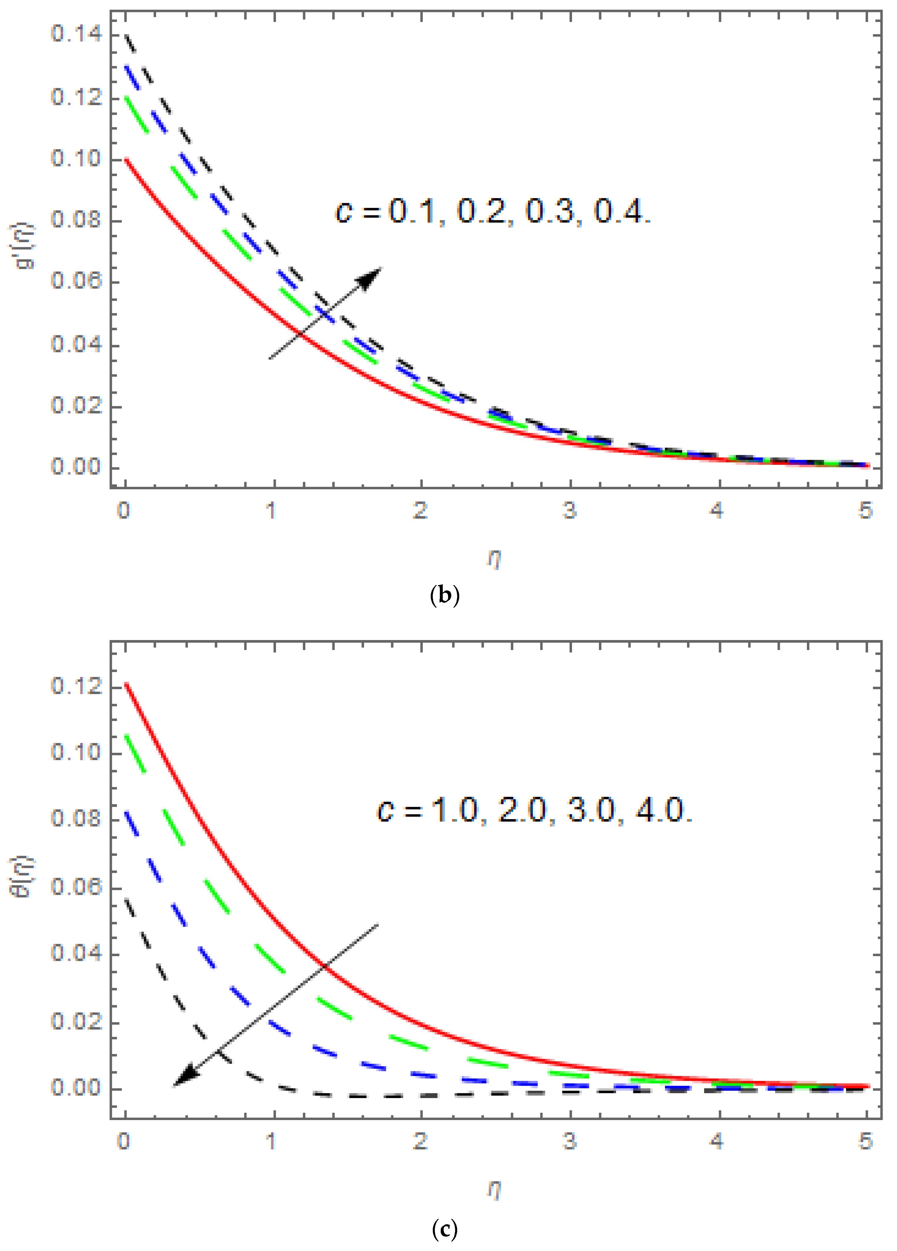
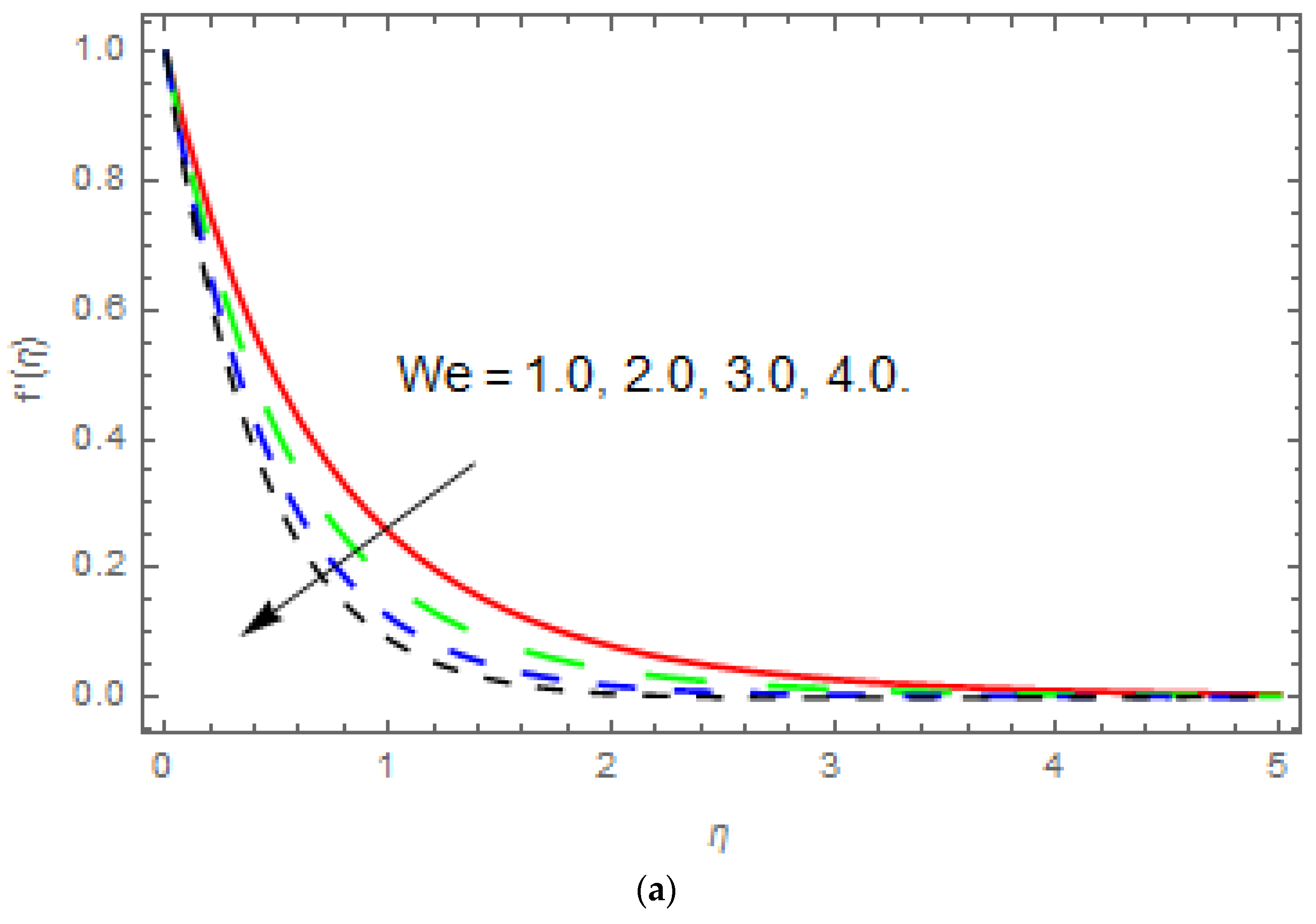
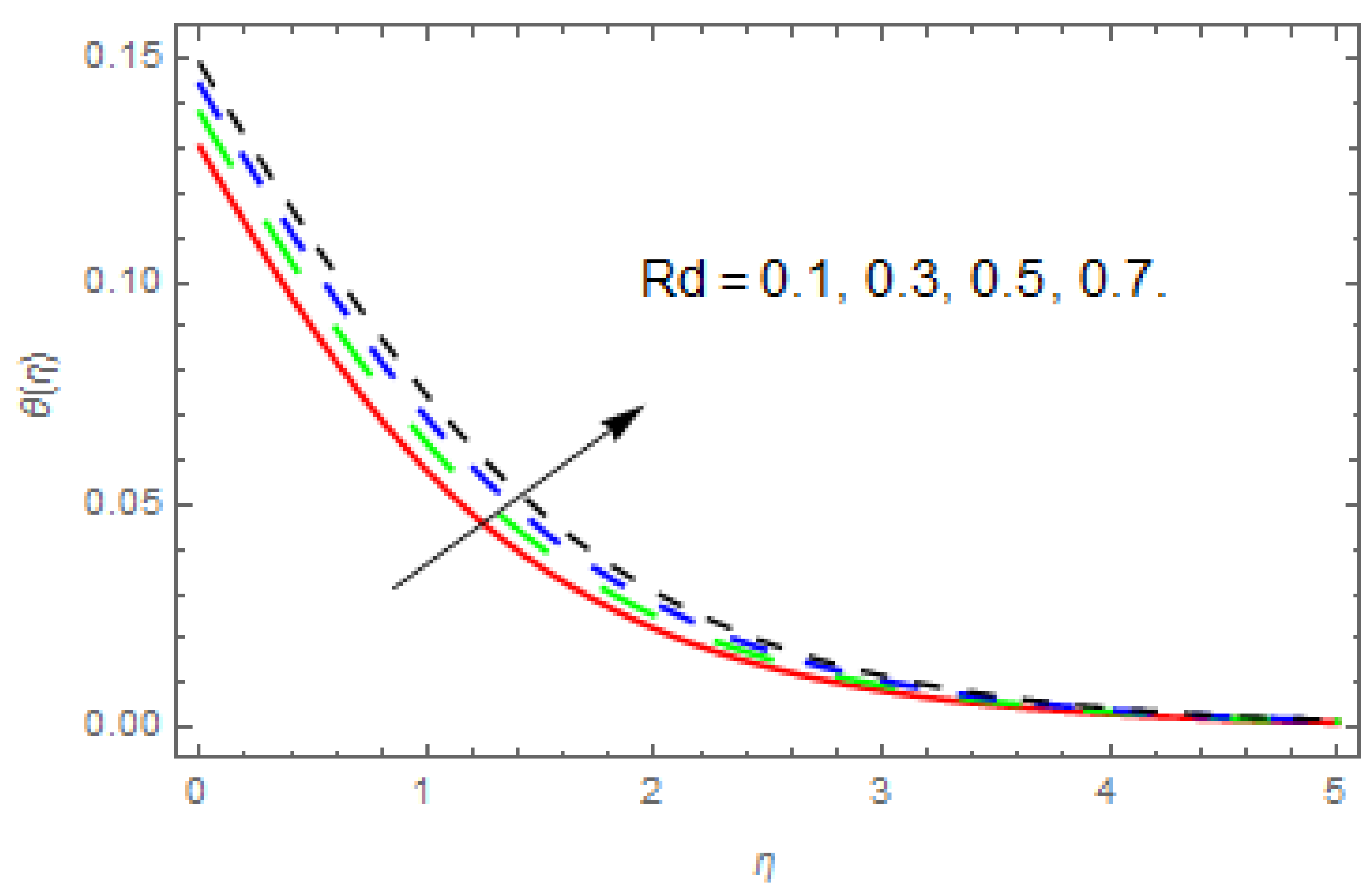
The impacts of emerging parameters have been presented in this section. The emerging parameters are stretching parameter ( c ) , Williamson parameter ( W e ) , Porosity parameter ( γ ) , thermal radiation parameter ( R d ) , Prandtl number ( Pr ) , thermophoresis parameter ( N t ) , Brownian motion parameter ( N b ) and Biot numbers ( B i 1 , B i 2 ) on velocities profiles ( f ( η ) , g ( η ) ) , temperature profile θ ( η ) and concentration profile ϕ ( η ) .Figure 1 shoe the physical sketch of the flow. Figure 2, Figure 3, Figure 4, Figure 5, Figure 6, Figure 7, Figure 8 and Figure 9 are plotted to observe the impact of these emerging parameters. Figure 2a is presented to see the impression of stretching parameter c on f ( η ) , g ( η ) , θ ( η ) and ϕ ( η ) . Physically the stretching parameter is the ratio of the fluid velocity along the x-direction to the fluid velocity along the y-direction. So this parameter is directly related to the velocity in the y-direction and related indirectly to the velocity in the x-direction. Because of this reason, the stretching parameter reduces f ( η ) in the x-direction, as shown in Figure 2a, and the stretching parameter enhances g ( η ) in the y-direction, as shown in Figure 2b. The influences of stretching parameter c on θ ( η ) and ϕ ( η ) are shown in Figure 2c,d. The increasing values of stretching parameter c show a reduction in θ ( η ) and ϕ ( η ) . Figure 3a,b shows the impact of ( W e ) on f ( η ) , g ( η ) in the x- and y-directions respectively. This parameter is the ratio of the relaxation to retardation time. The relaxation time is enhanced by increasing the Williamson parameter. Because of this, the fluid viscosity increases and as a result the velocity of fluid particles falls. Figure 4a,b shows the impact of ( γ ) on f ( η ) , g ( η ) . Physically, the porous medium influences the boundary layer, which leads to acceleration of the fluid. Due to this fact, the velocity profile reduces with the enhancement of the porosity parameter. Figure 5 shows the impact of ( R d ) on θ ( η ) . We see from the figure that the enhancement of ( R d ) upsurges θ ( η ) . ( R d ) plays a significant role in the heat transmission process. When we increase thermal radiation, the temperature of the boundary layer flow enhances. Figure 6 depicts the impact of ( Pr ) on θ ( η ) . Physically, with the increasing in the Prandtl number, the thermal diffusion diminishes, and also a small amplitude of oscillation in temperature occurs. Therefore, θ ( η ) reduces with increasing ( Pr ) . Figure 7a, b depicts the impact of ( N t ) on θ ( η ) and ϕ ( η ) . Here we see that the enhancement of ( N t ) reduces θ ( η ) and ϕ ( η ) . In addition, thermophoresis is high in Newtonian fluids as compared to non-Newtonian fluids. Figure 8a,b depicts the impact of ( N b ) on θ ( η ) and ϕ ( η ) . In Figure 8a, we see that θ ( η ) enhances with the enhancement of ( N b ) , while the opposite behavior of ( N b ) on ϕ ( η ) can be seen in Figure 8b. Figure 9a–c depicts the impact of ( B i 1 , B i 2 ) on θ ( η ) and ϕ ( η ) . From the figure, we can see that the increase of Biot numbers ( B i 1 , B i 2 ) causes an increase in the temperature and concentration profiles. The numerical values of the surface drag force and impact of the different parameters; W e , γ and c , are shown in Table 1. It is observed that increasing c and γ reduces the surface drag force f ( 0 ) and g ( 0 ) , while increasing W e augments the surface drag force f ( 0 ) and g ( 0 ) . Table 2 displays the numerical values of the heat transfer rate for the different embedded parameters; c , Pr , R d , N b and N t . It is concluded from Table 2, that the higher values of c , Pr and R d enhance the heat transfer rate, while the augmented value of N b and N t decrease the mass transfer rate. Table 2 presents the numerical values of the mass transfer rate for the different embedded parameters; c , L e , N b and N t . Here we observed that the higher values of c , N b and N t enhance the mass transfer rate, while the augmented value of L e reduces the heat transfer rate. Table 1, Table 2 and Table 3 display the validation of the current results with the previous published results. Both the current and previous results are compared and an excellent outcome is found. This verifies the validity of the current results along with the accurateness of the analytical method (HAM) we used in this research work.

5. Conclusions

In this article we have analyzed three-dimensional Williamson fluid flow past a linear porous and stretching sheet with the effect of thermal radiation. The system of equations has been solved by the homotopy analysis method. The impact of implanted parameters has been deliberated through graphs and discussed in detail. The concluding observations are as follows:
The velocity function f ( η ) reduces with enhancement of f ( η ) , ( W e ) and ( γ ) .
  • The velocity function g ( η ) improves with enhancement of the stretching parameter, while reduces with an increase in ( γ ) and ( W e ) .
  • The temperature function θ ( η ) improves with an increase in ( R d ) , ( N t ) , ( N b ) and ( B i 1 , B i 2 ) , while reduces with an increase in ( c ) and ( Pr ) .
  • The concentration function ϕ ( η ) enhances with an increase in ( N t ) and ( B i 2 ) , while reduces with an increase in ( c ) and ( N b ) .
  • It is observed that increasing c and γ reduces the surface drag forces f ( 0 ) and g ( 0 ) , while increasing W e augmented the surface drag forces f ( 0 ) and g ( 0 ) .
  • N t . It is concluded from Table 2, that the higher values of c , Pr and R d enhance the heat transfer rate, while the augmented values of N b and N t decline the heat transfer rate.

Author Contributions

A.S.K., Y.N. and Z.S. modeled and solved the problem and wrote the manuscript. S.I. and A.A.D. thoroughly checked the mathematical modeling and English corrections. W.K. contributed in the results and discussions and solution. All the corresponding authors finalized the manuscript after its internal evaluation.

Funding

This research was funded by National Natural Science Foundation of China No. [11471262].

Conflicts of Interest

The authors declare no conflict of interest.

References

  1. Sakiadis, B.C. Boundary-layer behavior on continuous solid surfaces: I. Boundary-layer equations for two-dimensional and axisymmetric flow. Am. Inst. Chem. Eng. 1961, 7, 26–28. [Google Scholar] [CrossRef]
  2. Crane, L.J. Flow past a stretching plate. Int. J. Appl. Mech. 1970, 21, 645–647. [Google Scholar] [CrossRef]
  3. Williamson, R.V. The flow of pseudoplastic materials. Int. J. Ind. Eng. Chem. 1929, 21, 1108–1111. [Google Scholar] [CrossRef]
  4. Ariel, P.D. The three-dimensional flow past a stretching sheet and the homotopy perturbation method. Int. J. Appl. Math. 2007, 54, 920–925. [Google Scholar] [CrossRef]
  5. Nadeem, S.; Haq, R.U.; Lee, C. MHD flow of a Casson fluid over an exponentially shrinking sheet. Sci. Iran. 2012, 19, 1550–1553. [Google Scholar] [CrossRef]
  6. Nadeem, S.; Akram, S. Peristaltic flow of a Williamson fluid in an asymmetric channel. Int. J. Nonlinear Sci. Numer. Simul. 2010, 15, 1705–1712. [Google Scholar] [CrossRef]
  7. Pop, I.; Na, T.Y. Unsteady flow past a stretching sheet. Int. J. Acta Mech. 1996, 4, 413–422. [Google Scholar] [CrossRef]
  8. Sakiadis, B.C. Boundary layer behavior on continuous solid surfaces and boundary layer on a continuous flat surface. J. Am. Inst. Chem. Eng. 1961, 7, 221–225. [Google Scholar] [CrossRef]
  9. Tsou, F.K.; Sparrow, E.M.; Goldstein, R.J. Flow and heat transfer in the boundary layer on a continuous moving surface. Int. J. Heat Mass Transf. 1967, 10, 219–235. [Google Scholar] [CrossRef]
  10. Malik, M.Y.; Bilal, S.; Salahuddin, T.; Khalil, U.R. Three-Dimensional Williamson Fluid Flow over a Linear Stretching Surface. Math. Sci. Lett. 2017, 6, 53–61. [Google Scholar] [CrossRef]
  11. Gupta, P.S.; Gupta, A.S. Heat and mass transfer on a stretching sheet with suction or blowing. Can. J. Chem. Eng. 1977, 55, 744–746. [Google Scholar] [CrossRef]
  12. Ericksod, L.E.; Fan, L.T.; Fox, V.G.; McCormack, P.D.; Crane, L. Phvsical fluid dynamics. Ind. Eng. Chem. 1966, 6, 19. [Google Scholar]
  13. Abdei-Aziz, M. Effect on the flow and heat transfer over an unsteady stretching sheet. Int. Commun. Heat Mass Transf. 2009, 36, 521–524. [Google Scholar] [CrossRef]
  14. Mukhopadyay, S. Effect of thermal radiation on unsteady mixed convection flow and heat treansfer over a porous stretching surface in porous medium. Int. J. Heat Mass Transf. 2009, 52, 3261–3265. [Google Scholar] [CrossRef]
  15. Shateyi, S.; Motsa, S.S. Thermal radiation effects on heat and mass transfer over an unsteady stretching surface. Math. Probl. Eng. 2009, 13, 965603. [Google Scholar] [CrossRef]
  16. Abdei-Aziz, M. Thermal-diffusion and diffusion-thermo effects on combined heat and mass transfer by hydromagnetic three-dimensional free convection over a permeable stretching surface with radiation. Phys. Lett. 2007, 372, 263–272. [Google Scholar] [CrossRef]
  17. Cortell, R. Effects of viscous dissipation and radiation on thermal boundary layer over a non-linearly stretching sheet. Phys. Lett. A 2008, 372, 631–636. [Google Scholar] [CrossRef]
  18. Ishak, A.; Nazar, R.; Pop, I. Heat transfer over a stretching surface with variable heat flux in viscous fluid. Phys. Lett. A 2008, 372, 559–561. [Google Scholar] [CrossRef]
  19. Dawar, A.; Shah, Z.; Islam, S.; Idress, M.; Khan, W.; Islam, S.; Gul, T. Impact of Thermal Radiation and Heat Source/Sink on Eyring–Powell Fluid Flow over an Unsteady Oscillatory Porous Stretching Surface. Math. Comput. Appl. 2018, 23, 20. [Google Scholar] [CrossRef]
  20. Dawar, A.; Shah, Z.; Islam, S.; Idress, M.; Khan, W. Magnetohydrodynamic CNTs Casson Nanofl uid and Radiative heat transfer in a Rotating Channels. J. Phys. Res. Appl. 2018, 1, 017–032. [Google Scholar] [CrossRef]
  21. Kashif, A.A.; Irfan, A.A.; Sikandar, M.A.; Ilyas, K. On the thermal analysis of magnetohydrodynamic Jeffery fluid via modern non integer order derivative. J. King Saud Univ. Sci. 2018. [Google Scholar] [CrossRef]
  22. Sheikholeslami, M. Numerical investigation of nanofluid free convection under the influence of electric field in a porous enclosure. J. Mol. Liq. 2018, 249, 1212–1221. [Google Scholar] [CrossRef]
  23. Sheikholeslami, M. Fe3O4-Ethylene glycol nanofluid forced convection inside a porous enclosure in existence of Coulomb force. Mol. Liq. 2018, 249, 429–437. [Google Scholar] [CrossRef]
  24. Sheikholeslami, M. Magnetic field influence on nanofluid thermal radiation in a cavity with tilted elliptic inner cylinder. J. Mol. Liq. 2017, 229, 137–147. [Google Scholar] [CrossRef]
  25. Sheikholeslami, M. Magnetohydrodynamic nanofluid forced convection in a porous lid driven cubic cavity using Lattice Boltzmann method. J. Mol. Liq. 2017, 231, 555–565. [Google Scholar] [CrossRef]
  26. Nadeem, S.; Ul Haq, R.; Noreen, S.A.; Khan, Z.H. MHD three-dimensional Casson fluid flow past a porous linearly stretching sheet. Alex. Eng. J. 2013, 52, 577–582. [Google Scholar] [CrossRef]
  27. Shah, Z.; Islam, S.; Ayaz, H.; Khan, S. Radiative Heat and Mass Transfer Analysis of Micropolar Nanofluid Flow of Casson Fluid between Two Rotating Parallel Plates with Effects of Hall Current. ASME J. Heat Transf. 2018. [Google Scholar] [CrossRef]
  28. Shah, Z.; Bonyah, E.; Islam, S.; Khan, W.; Ishaq, M. Radiative MHD thin film flow of Williamson fluid over an unsteady permeable stretching. Heliyon 2018, 4, e00825. [Google Scholar] [CrossRef] [PubMed]
  29. Shah, Z.; Dawar, A.; Islam, S.; Khan, I.; Ching, D.L.C. Darcy-Forchheimer Flow of Radiative Carbon Nanotubes with Microstructure and Inertial Characteristics in the Rotating Frame. Case Stud. Therm. Eng. 2018. [Google Scholar] [CrossRef]
  30. Khan, A.; Shah, Z.; Islam, S.; Khan, S.; Khan, W.; Khan, Z.A. Darcy–Forchheimer flow of micropolar nanofluid between two plates in the rotating frame with non-uniform heat generation/absorption. Adv. Mech. Eng. 2018, 10, 1–16. [Google Scholar] [CrossRef]
  31. Jawad, M.; Shah, Z.; Islam, S.; Islam, S.; Bonyah, E.; Khan, Z.A. Darcy-Forchheimer flow of MHD nanofluid thin film flow with Joule dissipation and Navier’s partial slip. J. Phys. Commun. 2018. [Google Scholar] [CrossRef]
  32. Khan, N.; Zuhra, S.; Shah, Z.; Bonyah, E.; Khan, W.; Islam, S. Slip flow of Eyring-Powell nanoliquid film containing graphene nanoparticles. AIP Adv. 2018, 8, 115302. [Google Scholar] [CrossRef]
  33. Bhatti, M.A.; Tehseen, R.; Mohammad, A.; Mohamed, Y.Z. Entropy generation on MHD Eyring-Powell nanofluid through a permeable stretching surface. Entropy 2016, 18, 224. [Google Scholar] [CrossRef]
  34. Darbari, B.; Rashidi, S.; Abolfazli Esfahani, J. Sensitivity analysis of entropy generation in nanofluid flow inside a channel by response surface methodology. Entropy 2016, 18, 52. [Google Scholar] [CrossRef]
  35. Hassan, M.; Marin, M.; Abdullah, A.; Ellahi, R. Convection heat transfer flow of nanofluid in a porous medium over wavy surface. Phys. Lett. A 2018, 382, 2749–2753. [Google Scholar] [CrossRef]
  36. Ahmed, Z.; Nouman, I.; Tehseen, A.; Rahmat, E. The sustainable characteristic of Bio-bi-phase flow of peristaltic transport of MHD Jeffery fluid in human body. Sustainability 2018, 10, 2671. [Google Scholar]
  37. Ghofrane, S.; Sébastien, P. Further investigation on laminar forced convection of nanofluid flows in a uniformly heated pipe using direct numerical simulations. Appl. Sci. 2016, 6, 332. [Google Scholar]
  38. Hussain, F.; Ellahi, R.; Zeeshan, A. Mathematical models of electro magnetohydrodynamic Multiphase Flows Synthesis with Nanosized Hafnium Particles. Appl. Sci. 2018, 8, 275. [Google Scholar] [CrossRef]
  39. Pieters, G.J.M.; Duijn, C.J.V. Transient growth in linearly stable gravity-driven flow in porous media. Eur. J. Mech. 2006, 25, 83–94. [Google Scholar] [CrossRef] [Green Version]
  40. Machrafi, H.; Rednikov, A.; Colinet, P.; Dauby, P.C. Bénard instabilities in a binary-liquid layer evaporating into an inert gas: Stability of quasi-stationary and time-dependent reference profiles. Eur. Phys. J. Spec. Top. 2011, 192, 71–81. [Google Scholar] [CrossRef] [Green Version]
  41. Ozen, O.; Narayanan, R. The physics of evaporative and convective instabilities in bilayer systems. Linear Theory Phys. Fluids 2004, 16, 4644. [Google Scholar] [CrossRef]
  42. Lapwood, E.R. Convection of a fluid in a porous medium. Math. Proc. Camb. Philos. Soc. 1948, 44, 508–521. [Google Scholar] [CrossRef]
  43. Sulochana, C.; Ashwinkumar, G.P.; Sandeep, N. Similarity solution of 3D Casson nanofluid flow over a stretching sheet with convective boundary conditions. J. Niger. Math. Soc. 2016, 35, 128–141. [Google Scholar] [CrossRef]
  44. Taza, G.; Abdul, S.K.; Saeed, I.; Aisha, M.A.; Ilyas, K.; Ali, S.A.; Abdullah, K.A. Muradullah. Heat transfer investigation of the unsteady thin film flow of Williamson fluid past an inclined and oscillating moving plate. Appl. Sci. 2017, 7, 369. [Google Scholar]
  45. Jang, S.P.; Choi, S.U.S. Role of Brownian motion in the enhanced thermal conductivity of nanofluids. Appl. Phys. Lett. 2004, 84, 4316. [Google Scholar] [CrossRef]
  46. Machrafi, H.; Lebon, G. The role of several heat transfer mechanisms on the enhancement of thermal conductivity in nanofluids. Contin. Mech. Thermodyn. 2016, 28, 1461–1475. [Google Scholar] [CrossRef] [Green Version]
  47. Anoop, K.B.; Kabelac, S.; Sundararajan, T.; Das, S.K. Rheological and flow characteristics of nanofluids: Influence of electroviscous effects and particle agglomeration. J. Appl. Phys. 2009, 106, 034909. [Google Scholar] [CrossRef]
  48. Azizian, R.; Doroodchi, D.; Moghtaderi, B. Effect of Nanoconvection Caused by Brownian Motion on the Enhancement of Thermal Conductivity in Nanofluids. Ind. Eng. Chem. Res. 2012, 51, 1782–1789. [Google Scholar] [CrossRef]
  49. Hammed, K.; Haneef, M.; Shah, Z.; Islam, I.; Khan, W.; Asif, S.M. The Combined Magneto hydrodynamic and electric field effect on an unsteady Maxwell nanofluid Flow over a Stretching Surface under the Influence of Variable Heat and Thermal Radiation. Appl. Sci. 2018, 8, 160. [Google Scholar] [CrossRef]
  50. Muhammad, S.; Ali, G.; Shah, Z.; Islam, S.; Hussain, A. The Rotating Flow of Magneto Hydrodynamic Carbon Nanotubes over a Stretching Sheet with the Impact of Non-Linear Thermal Radiation and Heat Generation/Absorption. Appl. Sci. 2018, 8, 482. [Google Scholar] [CrossRef]
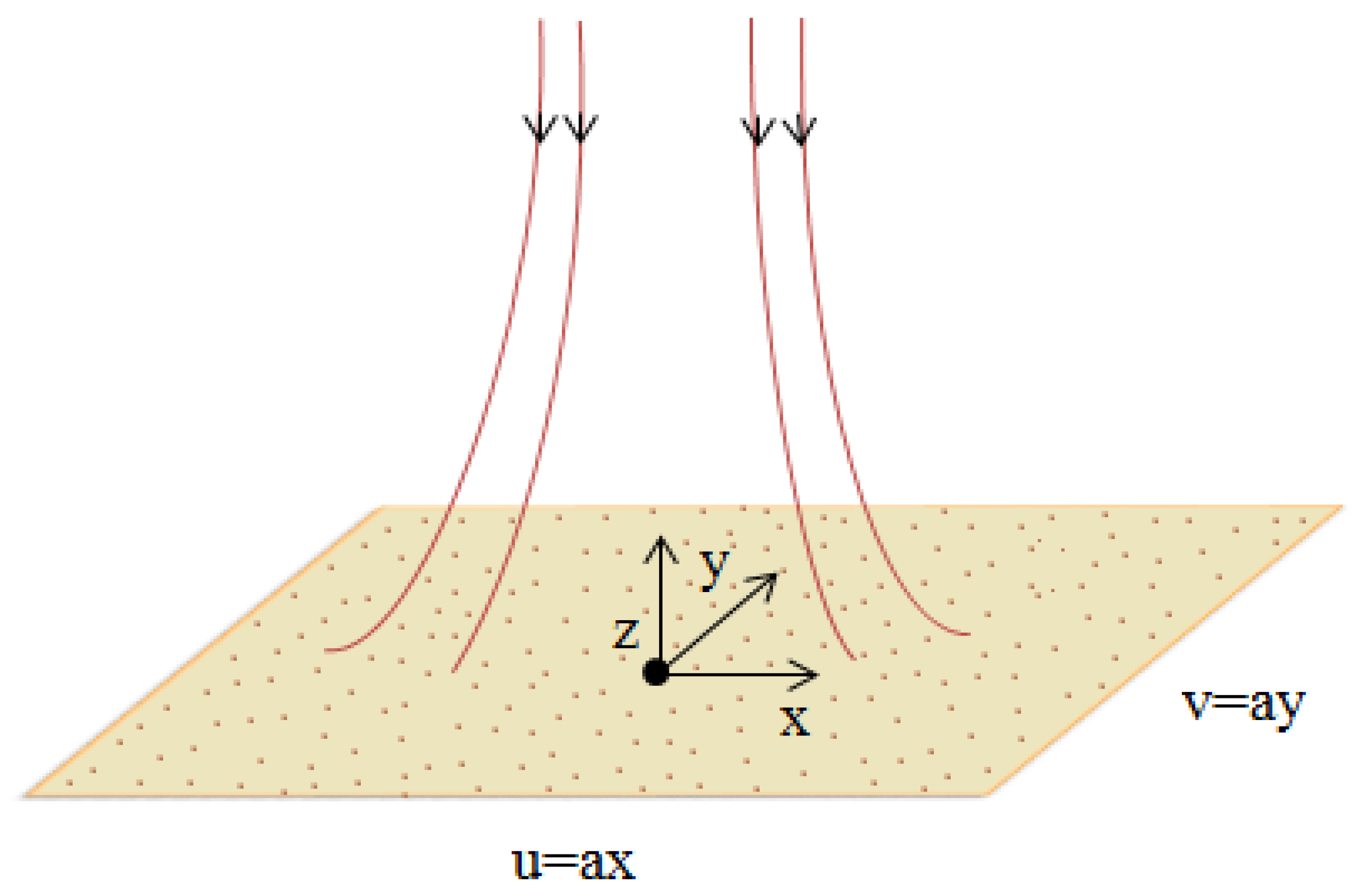
Figure 1. Physical representation of the problem.
Applsci 08 02244 g001
Figure 2. (ad) Effect of the stretching parameter on velocity, temperature, and concentration profiles. (a) Effect of c on f ( η ) , when W e = 0.1 , γ = 0.2. (b) Effect of c on g ( η ) , when W e = 0.1 , γ = 0.2. (c) Effect of c on θ ( η ) , when B i 1 = 0.1 , N b = 0.4 , N t = 0.5 , Pr = 0.6 , L e = 0.7 , R d = 0.8. (d) Effect of c on ϕ ( η ) , when B i 1 = 0.1 , B i 2 = 0.2 , N b = 0.4 , N t = 0.5 .
Applsci 08 02244 g002aApplsci 08 02244 g002bApplsci 08 02244 g002c
Figure 3. (a,b) Influence of the Williamson parameter on velocity profiles. (a) Effect of W e on f ( η ) , when c = 0.1 , γ = 0.2. (b) Effect of W e on g ( η ) , when c = 0.1 , γ = 0.2. .
Applsci 08 02244 g003aApplsci 08 02244 g003b
Figure 4. (a,b) Effect of ( γ ) on f ( η ) , g ( η ) . (a) Influence of γ on f ( η ) , when c = 0.1 ,   W e = 0.2. (b) Influence of γ on g ( η ) , when c = 0.1 , W e = 0.2 .
Applsci 08 02244 g004aApplsci 08 02244 g004b
Figure 5. Effect of the thermal radiation parameter R d on θ ( η ) , when B i 1 = 0.1 , N b = 0.4 , N t = 0.5 , Pr = 0.6 , L e = 0.7 , c = 0.8 .
Applsci 08 02244 g005
Figure 6. Effect of Prandtl number Pr on θ ( η ) , when B i 1 = 0.1 , N b = 0.4 , N t = 0.5 , R d = 0.6 , L e = 0.7 ,   c = 0.8 .
Applsci 08 02244 g006
Figure 7. (a,b) Effect of the thermophoresis parameter on temperature and concentration profiles. (a) Effect of N t on θ ( η ) , when B i 1 = 0.1 , N b = 0.4 , R d = 0.5 , Pr = 0.6 , L e = 0.7 ,   c = 0.8. (b) Effect of N t on ϕ ( η ) , when B i 1 = 0.1 , B i 2 = 0.2 , N b = 0.4 , L e = 0.7 , c = 0.8 .
Applsci 08 02244 g007aApplsci 08 02244 g007b
Figure 8. (a,b) Effect of the Brownian motion parameter on temperature and concentration profiles. (a) Effect of N b on θ ( η ) , when B i 1 = 0.1 , R d = 0.4 , N t = 0.5 , Pr = 0.6 , L e = 0.7 , c = 0.8. (b) Effect of N b on ϕ ( η ) , when B i 1 = 0.1 , B i 2 = 0.2 , N t = 0.4 , L e = 0.7 , c = 0.8 .
Applsci 08 02244 g008aApplsci 08 02244 g008b
Figure 9. (ac) Effect of the Biot numbers on temperature and concentration profiles. (a) Effect of B i 1 on θ ( η ) , when R d = 0.1 , N b = 0.4 , N t = 0.5 , Pr = 0.6 , L e = 0.7 , c = 0.8. (b) Effect of B i 1 on ϕ ( η ) , when N b = 0.1 , B i 2 = 0.2 , N t = 0.4 , L e = 0.7 , c = 0.8. (c) Effect of B i 2 on ϕ ( η ) , when N b = 0.1 , B i 1 = 0.2 , N t = 0.4 , L e = 0.7 , c = 0.8 .
Applsci 08 02244 g009aApplsci 08 02244 g009b
Table 1. Numerical values of surface drag force for different embedded parameters.
c W e   γ C f   for   f ( 0 ) Previous Results [43] C f   for   f ( 0 )   Present   Results C f   for   g ( 0 ) Previous Results [43] C f   for   g ( 0 )   Present   Results
1.00.10.5−1.489532−1.23942−0.695215−2.04702
1.1 −1.564022−1.25192−1.564022−2.23996
1.2 −1.682498−1.26417−2.647314−2.38904
0.2 −1.731420−1.06979−1.892121−1.22441
0.3 −1.544321−0.83279−1.744322−0.42052
0.4 −1.324151−0.38181−1.2121410.35420
0.6−1.829575−1.28570−1.829575−1.82788
0.7−2.083805−1.32900−2.083805−1.60457
0.8−2.310564−1.36945−2.310564−1.38981
Table 2. Numerical values of heat transfer rate for different embedded parameters.
c Pr   R d   N t   N b   N u Previous Results [43] N u   Present   Results
1.00.40.30.010.010.2618960.119212
1.1 0.3182720.120401
1.2 0.3791450.121608
0.5 -0.127300
0.6 -0.134579
0.7 0.140705
0.4 -0.155214
0.5 -0.192457
0.6 -0.241744
0.02 0.2937700.155120
0.06 0.2742990.154747
0.08 0.2556290.154467
0.030.2856470.155044
0.050.2537390.154874
0.070.2227390.154704
Table 3. Numerical values of mass transfer rate for different embedded parameters.
c Le N t   N b   S h Previous Results [43] S h   Present   Results
1.00.10.010.010.2239240.291024
1.1 0.2555070.293757
1.2 0.2892660.296524
0.2 -0.291022
0.3 -0.291021
0.4 -0.291019
0.02 0.2132080.200865
0.03 0.1445150.290705
0.04 0.0893020.290545
0.020.2722750.290847
0.030.2860510.290671
0.040.2905930.290494