Article

A 20 W, Less-Than-1-kHz Linewidth Linearly Polarized All-Fiber Laser

1
State Key Laboratory of Transient Optics and Photonics, Xi’an Institute of Optics and Precision Mechanics, Chinese Academy of Sciences, Xi’an 710119, China
2
University of Chinese Academy of Sciences, Beijing 100049, China
*
Author to whom correspondence should be addressed.
Appl. Sci. 2018, 8(12), 2593; https://doi.org/10.3390/app8122593
Submission received: 12 November 2018 / Revised: 8 December 2018 / Accepted: 8 December 2018 / Published: 12 December 2018

Abstract

:
We report a continuous-wave high-output power and narrow-linewidth all-fiber laser at 1550 nm with the master oscillator power amplifier (MOPA) configuration. An all-fiber distributed feedback seed laser was boosted by three cascaded fiber amplifiers. In the experiment, we adopted a large-mode-area (LMA) Er3+:Yb3+-co-doped polarization-maintaining fiber to increase nonlinear thresholds and avoided the broadening of the laser linewidth. A linear-polarization fiber laser with average output power of 20 W, linewidth of 0.88 kHz, and power jitter less than 2% was finally achieved.

1. Introduction

A high-power narrow linewidth laser source around 1.5 μm has aroused wide attention [1,2] because of its eye-safe property and its application in the field of long-distance coherent systems such as ranging, free-space telecommunication, laser remote sensing, and synthetic aperture light detection and ranging (LIDAR)(SAL) [3,4,5,6,7,8,9]. For long-distance coherent detection, high-output power ensures a farther transmission distance, and narrow linewidth ensures a higher coherence signal-to-noise ratio (SNR). Therefore, obtaining a laser with narrow linewidth is very meaningful under a high-power output. As it is difficult to obtain a single longitudinal mode in a high-power fiber laser oscillator, the master oscillator power amplifier (MOPA) configuration is commonly used. Typically, in the MOPA configuration, a low-power seed laser with narrow linewidth is amplified through several stages until the high-output power is reached.
With a high-power MOPA laser in the 1.5 μm region, a continuous output power of 297 W was achieved at 1567 nm using a cladding-pumped Er3+:Yb3+-co-doped fiber (EYDF) oscillator [10], and 55 W output power was obtained at 1555 nm using a core-pumped Er3+-doped fiber oscillator [11]. However, in these previous reports, the linewidth of the laser was not taken into consideration. As the important narrow linewidth regime wavelength neared 1550 nm, 11.6 W output power at 1538.8 nm with linewidth of 6 kHz pumped by a 1480 nm cascaded Raman fiber laser [12], 10.9 W output power at 1560 nm with linewidth of 3.5 kHz [13], 56.4 W with a linewidth of 83.5 kHz at 20 dB [14], and a 23 W single-frequency laser obtained with a laser linewidth of 1.7 kHz were reported [15]. It can be seen that the linewidth increased with the improvement of output power. The main difficulties in achieving high-output power with narrow linewidth are caused by nonlinear effects and thermal management in the amplification process. When the laser linewidth is narrower, than the Brillouin gain bandwidth, the stimulated Brillouin scattering (SBS), becomes the predominant limitation to achieve higher output power. In order to increase the SBS threshold, the application of a strain to the active fiber [16], a temperature distribution along the active fiber [17], a longitudinal variation in the dopant concentrations [18], and a change in the core radius [19] was used. However, the most basic approach is to increase the effective mode area and reduce the length of the fiber. The SBS threshold in the gain fiber is related to the effective mode field area of the fiber and the actual length of the fiber. When the mode area of the gain fiber is larger, the SBS threshold is higher; when the fiber length is greater, the SBS threshold is smaller.
In this paper, we report a 1550 nm high-power narrow-linewidth all-fiber linearly polarized laser with the MOPA technology. By adopting three cascaded erbium ytterbium co-doping amplifiers, we obtained an output power of 20 W laser source with a linewidth of 0.88 kHz, a power stability less than 2%, and an optical SNR over 40 dB. The amplifiers consisted of core-pumped signal-mode Er3+-doped polarization-maintaining fibers, cladding-pumped Er3+:Yb3+-co-doped double-clad polarization-maintaining fibers, and cladding-pumped Er3+:Yb3+ -co-doped LMA polarization-maintaining fibers, which avoided nonlinear effects, in particular SBS.

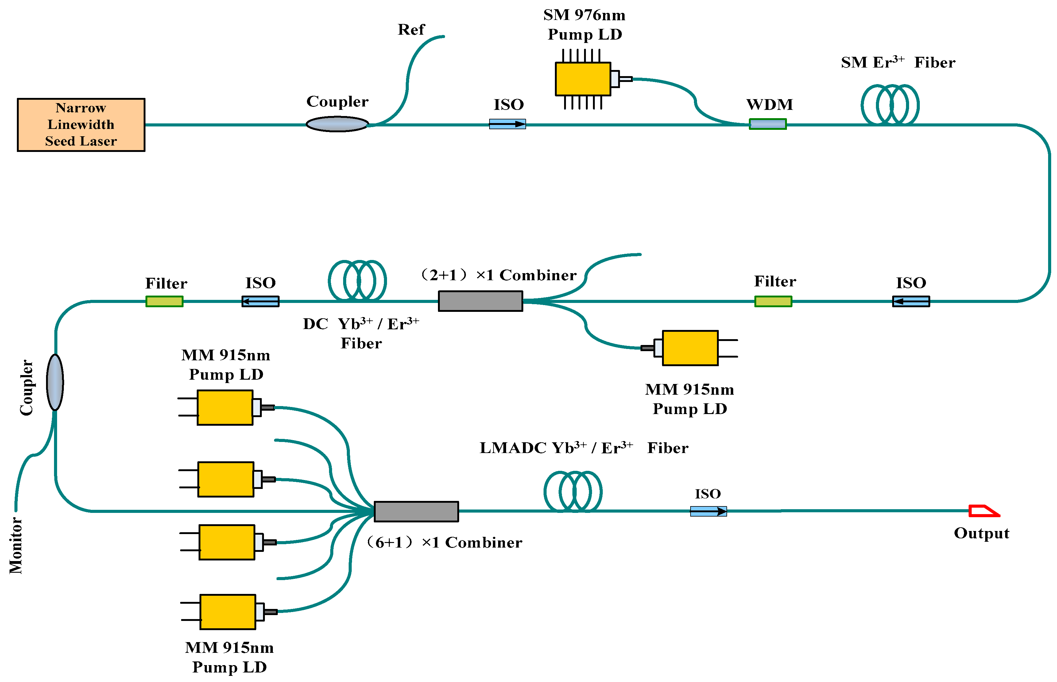
2. Experimental Setup

The setup of the experiment for the Er3+:Yb3+-co-doped fiber amplifier (EYDFA) system is shown in Figure 1. A linearly polarized narrow-linewidth laser of 1550 nm with the linewidth of 0.4 kHz was used as the seed source. The amplifier consisted of a preamplifier, a boost amplifier, a power amplifier. The preamplifier was based on 1 m-long Er3+-doped single-mode polarization-maintaining fiber with core diameter of 7 μm and clad diameter of 125 μm, core-pumped by aa wavelength-stabilized 976 nm laser diode (LD) through a polarization-maintaining wavelength division multiplex (WDM). The fiber pump absorption coefficient was 24 dB/m at the wavelength of 976 nm. The wavelength of the pump LD was stabilized at 976 nm in order to match the peak absorption of the active fiber. The boost amplifier was based on 6 m-long double-cladding Er3+:Yb3+-co-doped polarization-maintaining active fiber with core diameter of 6 μm and inner clad diameter of 125 μm, whose absorption coefficient was 0.8 dB/m, cladding-pumped by 915 nm LD through a ( 2 + 1 ) × 1 pump combiner. The power amplifier was based on 4 m-long cladding-pumped large core Er3+:Yb3+ -co-doped polarization-maintaining active fiber with core diameter of 25 μm and inner clad diameter of 300 μm. The fiber core was an octagon preform in order to increase pump absorption; the numerical aperture (NA) of the core and the inner clad were 0.09 and 0.46, respectively. The pump absorption coefficient was 2.9 dB/m at the wavelength of 915 nm. The amplifier could boost the signal to 20 W at the 75 W pump power of 915 nm through a ( 6 + 1 ) × 1 polarization-maintaining pump combiner. All components were placed on the optical platform, while the power amplification section was placed on a water-cooled platform for active cooling.
Each amplifier was connected through a polarization-maintaining optical fiber isolator (ISO). Between the amplifiers, ISOs were used to avoid the reflected laser, unabsorbed pump light and the amplified spontaneous emission (ASE) and to prevent the frontal stage components from being damaged by backscattering light. To achieve a compact all-fiber structure, fusion welding connection was employed in the proposed fiber laser.
The output power was measured by a digital power meter with a photodiode sensor head. A delayed self-heterodyne was used to measure laser linewidth [20,21]. Figure 2 presents the diagram of the linewidth measurement system. The laser was split into two paths by a splitter in a Mach–Zehnder (MZ) fiber interferometer. One beam was delayed by the single-mode optical fiber. The other beam was directed through an acousto-optic modulator (AOM) frequency shifter operating at 150 MHz. The two beams were recombined by a coupler to generate a beat signal and transported into a photodetector to produce the power spectrum, whose shape and width were related to the laser linewidth. When the delayed length was much longer than the laser coherent length, the power spectrum was the laser spectrum lineshape, fitting the power spectrum and measuring 20 dB in width corresponding to the linewidth of the laser. When the laser linewidth became narrower and narrower, hundreds of kilometers of delayed fiber were needed to detect the sub-kilohertz laser linewidth. However, the broadening of the laser linewidth could be avoided when the ultra-long delayed fiber was used in the self-heterodyne [22]. To decrease the linewidth broadening induced by the ultra-long delayed fiber, the short-delayed heterodyne method should be used. If the delay time is less than the laser’s coherence time, there will be a delta function peak and coherent envelopes in the power spectrum [23]. In this case, the laser linewidth can be measured by the amplitude difference comparison of the coherent envelope method [24]. The laser linewidth can be calculated by comparing the contrast difference between the first sideband near the center-frequency peak and the trough of the coherent envelope of the power spectrum. At the same time, we used an optical spectrum analyzer to monitor nonlinear effects in the process of amplification.

3. Experimental Results and Analyses

In the experiment, the seed laser was a distributed feedback (DFB) fiber laser with an output power of 1 mW and a linewidth of 0.4 kHz. The spectrum of the seed laser was measured by an optical spectrum analyzer (YOKOGAWA, AQ6375), as shown in Figure 3. The central wavelength of the seed laser was 1549.6 nm, and the SNR of the laser signal was greater than 47 dB.
First, we used two stages of amplifiers to enlarge the power of the seeder to 1 W. In the preamplifier, the 1 mW seeder could be boosted to 50 mW. The output spectrum of the first preamplifier wass amplified spontaneous emission (ASE)-free. The boost amplifier could boost the first-class signal power to 1 W at the pump LD power of 6.5 W. Figure 4 shows the output spectrum of the second amplifier, where the SNR was 45 dB. The spectral envelope observed around 1560 nm is the noise amplification of the seeder.
The last stage was the power amplifier; the maximum output power of 20 W was obtained from the power amplifier stage under the launched pump power of 75 W, with no occurrence of saturation effect, and the corresponding optical efficiency was 26.7%. In order to increase the nonlinear effect threshold in the fiber and reduce the ASE noise, the length of the gain fiber was reduced, so that the amplification efficiency was relatively low. Figure 5 shows the signal-output power of the last power amplifier as a function of the launched pump power. The yellow line is the laser-output power without the isolator, and the blue line is the laser-output power after the isolator is added. The isolator insertion loss in the last level was 0.8 dB. Because of the insertion loss of the isolator, the output power was reduced after laser input. The spectrum and power of the output signal were monitored to observe whether the SBS occurred. Figure 6a shows the output spectrum of the power amplifier at the maximum output power. In the process of power amplification, the noise near 1560 nm was amplified at the same time, and the SNR was still more than 40 dB. The linewidth was achieved by the delayed self-heterodyne method with the analysis of the frequency spectrum. A fiber-coupled InGaAs-biased detector was used to detect the beat signal. The frequency spectrum of the beat signal was obtained with a spectrum analyzer (Agilent E4447A, Santa Clara, CA, USA). Figure 6b shows the actual recorded power spectrum at the maximum output power of the laser measured with 25 km delayed fiber. The delta function peak of the power spectrum and the coherent envelopes appearing on the two wings are caused by the interference of the two beat frequency beams and indicate that the coherence length of the laser was greater than the delayed fiber of 25 km. In order to accurately obtain the laser linewidth, the amplitude difference comparison of the coherent envelope method was used to measure the laser linewidth [24]. Since a long delayed fiber broadens the laser linewidth and a short delayed fiber leads to inaccurate coherent envelope in self-heterodyne measurements, the length of the delayed fiber should be chosen properly, such as 3 km, 4 km, or 5 km [24]. The laser linewidth was calculated through the value of contrast difference between the first sideband near the center frequency peak and the trough of the coherent envelope of the power spectrum. Figure 7 shows the actual recorded power spectrum of a 3 km delay length. The value of contrast difference between the first sideband near the center frequency peak and the trough was 16.3 dB. Therefore, the laser linewidth was calculated to be 0.88 kHz by the relationship between the laser linewidth and the contrast difference of the second peak and the second trough [24]. By observing the spectrum and linewidth broadening, the nonlinear effect does not appear obvious. The increase of the linewidth was mainly attributed to the increase of incoherent components, such as the noise of the seeder near 1560 nm. With the raising of pump power, the noise near 1560 nm was boosted in the amplifier as well. The increment of the noise decreased the SNR and broadeds the linewidth.
In the experiment, the amplifier could boost the power of the signal from 1 mW to 20 W. The gain of the entire amplifier was 34.8 dB. We recorded the output power of the laser in 45 min, and the stability of the laser could reach 2%, as illustrated in Figure 8. Beam quality was measured by a Thorlabs BP109IR beam-quality analyzer. Figure 9 shows the beam quality M2 measurement results. The laser M2 factor was 1.35 in the x-direction and 1.33 in the y-direction. The polarization extinction ratio (PRE) of the laser was measured in the experiment. The PRE was 18 dB.

4. Conclusions

In conclusion, we demonstrated an all-fiber high-power narrow-linewidth polarization-maintaining continuous laser system, whose output power was 20 W and linewidth was 0.88 kHz at the wavelength of 1550 nm. The laser was comprised of a single-frequency fiber laser seed source that was amplified through a three-amplification-stage MOPA system up to a power of 20 W. The power amplifier consisted of a cladding-pumped large-core EYDF with a 25 μm core and a 300 μm clad, which helped to increase nonlinear thresholds. Neither obvious SBS nor other new wavelengths were observed in the proposed cascaded MOPA system. We are looking forward to achieving a higher power output and maintaining a narrow linewidth at the same time by increasing pump power and cooling the EYDF. The demonstrated high-power narrow-linewidth laser could have applications in laser remote sensing, synthetic aperture lidar, or range finding.

Author Contributions

Conceptualization, M.X. and C.G.; Data curation, M.X.; Formal analysis, M.X.; Funding acquisition, C.G. and S.Z.; Investigation, L.N., J.Z., and H.H.; Methodology, M.X.; Project administration, S.Z. and C.S.; Validation, M.X.; Writing—original draft, M.X.; Writing—review & editing, M.X. and C.G.

Funding

“National Natural Science Foundation of China” grant number “61875227” and “National Key Scientific Instrument and Equipment Development” grant number “2013YQ310633”.

Acknowledgments

This works was supported by the “National Natural Science Foundation of China” (Nos.61875227) and the “National Key Scientific Instrument and Equipment Development” Project (Grant No. 2013YQ310633).

Conflicts of Interest

The authors declare no conflict of interest.

References

  1. Zhang, X.; Diao, W.; Liu, Y.; Zhu, X. Eye-Safe single –frequency single-mode polarized all-fiber pulsed laser with peak power of 361W. Appl. Opt. 2014, 53, 2465–2469. [Google Scholar] [CrossRef] [PubMed]
  2. Hofmann, P.; Voigtlander, C.; Nolte, S.; Peyghambarian, N.; Schulzgen, A. 550-mW Output Power From a Narrow Linewidth All-Phosphate Fiber Laser. J. Lightw. Technol. 2013, 31, 756–760. [Google Scholar] [CrossRef]
  3. Jeong, Y.; Sahu, J.K.; Soh, D.B.S.; Codemard, C.A.; Nilsson, J. High-power tunable single-frequency single-mode erbium:ytterbium codoped large-core fiber master-oscillator power amplifier source. Opt. Lett. 2005, 30, 2997–2999. [Google Scholar] [CrossRef] [PubMed]
  4. Liu, C.; Qi, Y.; Ding, Y.; Zhou, J.; Dong, J.; Wei, Y.; Lou, Q. All-fiber, high power single-frequency linearly polarized ytterbium-doped fiber amplifier. Chin. Opt. Lett. 2011, 9, 031402. [Google Scholar]
  5. Philippov, V.; Codemard, C.; Jeong, Y.; Alegria, C.; Sahu, J.; Nilsson, J. High-energy in-fiber pulse amplification for coherent lidar applications. Opt. Lett. 2004, 29, 2590–2592. [Google Scholar] [CrossRef] [PubMed]
  6. Bouteyre, A.D.; Canat, G.; Valla, M.; Augere, B.; Besson, C.; Goular, D.; Lombard, L.; Cariou, J.; Durecu, A.; Fleury, D. Pulsed 1.5-μm lidar for axial aircraft wake vortex detection based on high brightness largecore fiber amplifier. IEEE J. Sel. Top. Quantum Electron. 2009, 15, 441–450. [Google Scholar] [CrossRef]
  7. Zhu, X.; Liu, J.; Bi, D.; Zhou, J.; Diao, W.; Chen, W. Development of all-solid coherent Doppler wind lidar. Chin. Opt. Lett. 2012, 10, 012801. [Google Scholar]
  8. Jiang, M.; Xu, H.; Zhou, P.; Zhao, G.; Gu, X. All-fiber, narrow linewidth and linearly polarized fiber laser in a single-mode–multimode-single-mode cavity. Appl. Opt. 2016, 55, 6121–6124. [Google Scholar] [CrossRef]
  9. Wright, M.W.; Yao, H.; Marciante, J.R. Resonant pumping of Er-doped fiber amplifiers for improved laser efficiency in free-space optical communications. JPL IPN Prog. Rep. 2012, 1–20, 42–189. [Google Scholar]
  10. Jeong, Y.; Yoo, S.; Codemard, C.; Nilsson, J.; Sahu, J.; Payne, D.N.; Horley, R.; Turner, P.W.; Hickey, L.; Harker, A.; et al. Erbium: Ytterbium codoped large-core fiber laser with 297-W continuous-wave output power. IEEE J. Sel. Top. Quantum Electron. 2007, 13, 573–579. [Google Scholar] [CrossRef]
  11. Nicholson, J.W. High-power, continuous wave, erbium-doped fiber laser pumped by a 1480 nm Raman fiber laser. Int. Soc. Opt. Photonics 2012, 8237, 28370K. [Google Scholar]
  12. Fujisaki, A.; Matsushita, S.; Kasai, K.; Yoshida, M.; Hirooka, T.; Nakazawa, M. An 11.6 W output, 6 kHz linewidth, single-polarization EDFA-MOPA system with a 13C2H2 frequency stabilized fiber laser. Opt. Express 2015, 23, 1081–1087. [Google Scholar] [CrossRef] [PubMed]
  13. Yang, C.; Xu, S.; Mo, S.; Li, C.; Feng, Z.; Chen, D.; Yang, Z.; Jiang, Z. 10.9 W kHz-linewidth one-stage all-fiber linearly-polarized MOPA laser at 1560 nm. Opt. Express 2013, 21, 12546–12551. [Google Scholar] [CrossRef] [PubMed]
  14. Bai, X.; Sheng, Q.; Zhang, H.; Fu, S.; Shi, W.; Yao, J. High-Power All-Fiber Single-Frequency Erbium–Ytterbium Co-Doped Fiber Master Oscillator Power Amplifier. IEEE Photonics J. 2015, 7, 1–6. [Google Scholar]
  15. Yang, C.; Guan, X.; Zhao, Q.; Wu, B.; Feng, Z.; Gan, J.; Cheng, H.; Peng, M.; Yang, Z.; Xu, S. High-power and near-shot-noise-limited intensity noise all-fiber single-frequency 1.5 μm MOPA laser. Opt. Express 2017, 25, 13324–13331. [Google Scholar] [CrossRef] [PubMed]
  16. Yoshizawa, N.; Imai, T. Stimulated Brillouin scattering suppression by means of applying strain to fiber with cabling. J. Lightw. Technol. 1993, 11, 1518–1522. [Google Scholar] [CrossRef]
  17. Hansryd, J.; Dross, F.; Westlund, M.; Andrekson, P.A.; Knudsen, S.N. Increase of SBS threshold in a short highly nonlinear fiber by applying a temperature distribution. J. Lightw. Technol. 2001, 19, 1691–1697. [Google Scholar] [CrossRef]
  18. Shiraki, K.; Ohashi, M.; Tateda, M. Performance of strain-free stimulated Brillouin scattering suppression fiber. J. Lightw. Technol. 1996, 14, 549–554. [Google Scholar] [CrossRef]
  19. Shiraki, K.; Ohashi, M.; Tateda, M. Suppression of stimulated Brillouin scattering in a fiber by changing the core radius. Electron. Lett. 1995, 31, 668–669. [Google Scholar] [CrossRef]
  20. Chen, M.; Meng, Z.; Wang, J.; Chen, W. Ultra-narrow linewidth measurement based on Voigt profile fitting. Opt. Express 2015, 23, 6803–6808. [Google Scholar] [CrossRef]
  21. Xie, D.; Deng, D.; Guo, L.; Yang, J.; Wei, H. Line-Width Measurement Method of Narroww Line Width Lasers. Laser Optoelectrn. Prog. 2013, 50, 010006. [Google Scholar]
  22. Mercer, L. 1/f frequency noise effects on self-heterodyne linewidth measurements. J. Lightw. Technol. 1991, 9, 485–493. [Google Scholar] [CrossRef] [Green Version]
  23. Okoshi, T.; Kikuchi, K.; Nakayama, A. Novel method for high resolution measurement of laser output spectrum. Electron. Lett. 1980, 16, 630–631. [Google Scholar] [CrossRef]
  24. Huang, S.; Zhu, T.; Cao, Z.; Liu, M.; Deng, M.; Liu, J.; Li, X. Laser Linewidth Measurement Based on Amplitude Difference Comparison of Coherent Envelope. IEEE Photonics Technol. Lett. 2016, 28, 759. [Google Scholar] [CrossRef]
Figure 1. Schematic diagram of the experimental setup for the Er3+:Yb3+-co-doped fiber amplifier (EYDFA) system.
Applsci 08 02593 g001
Figure 2. The diagram of the linewidth measurement system.
Applsci 08 02593 g002
Figure 3. Output spectrum of the seed signal.
Applsci 08 02593 g003
Figure 4. Output spectrum of the second preamplifier.
Applsci 08 02593 g004
Figure 5. Output power of the last pump amplifier versus pump power.
Applsci 08 02593 g005
Figure 6. Output spectrum and power spectrum of 25 km delayed self-heterodyne of 20 W laser signal. (a) Shows the output spectrum of the power amplifier at the maximum output power. (b) Shows the actual recorded power spectrum at the maximum output power of laser measured with 25 km delayed fiber.
Applsci 08 02593 g006aApplsci 08 02593 g006b
Figure 7. Actual recorded power spectrum of a 3 km delay length.
Applsci 08 02593 g007
Figure 8. Output power jitter in 45 min.
Applsci 08 02593 g008
Figure 9. Beam quality M2 measurement results.
Applsci 08 02593 g009

