Featured Application
This work is beneficial to the design of cutting tool and improvement of machining quality in milling CFRP. The likely users could be CFRP product processors and cutting tool manufacturers.
Abstract
Carbon fiber reinforced plastic (CFRP) is typically hard to process, because it is easy for it to generate processing damage such as burrs, tears, delamination, and so on in the machining process. Consequently, this restricts its wide spread application. This paper conducted a comparative experiment on the cutting performance of the two different-structure milling cutters, with a helical staggered edge and a rhombic edge, in milling carbon fiber composites; analyzed the wear morphologies of the two cutting tools; and thus acquired the effect of the tool structure on the machined surface quality and cutting force. The results indicated that in the whole cutting, the rhombic milling cutter with a segmented cutting edge showed better wear resistance and a more stable machined surface quality. It was not until a large area of coating shedding occurred, along with chip clogging, that the surface quality decreased significantly. At the stage of coating wear, the helical staggered milling cutter with an alternately arranged continuous cutting edge showed better machined surface quality, but when the coating fell off, its machined surface quality began to reveal damage such as groove, tear, and fiber pullout. Meanwhile, burrs occurred at the edge and the cutting force obviously increased. By contrast, for the rhombic milling cutter, both the surface roughness and cutting force increased relatively slowly.
1. Introduction
Carbon fiber reinforced plastic (CFRP) has excellent physical properties such as light weight, high strength, and corrosion resistance, and thus it is widely applied to aviation, aerospace, automobile, and so on [1,2,3]. However, its poor thermal conductivity, low inter laminar strength, and anisotropy [4] have easily resulted in the occurrence of damage such as burrs, tears, and delamination, as well as fast tool wear and failure in the machining [5,6,7]. Meanwhile, both the single type of cutting tools for cutting CFRP as well as the serious problems of the tool durability and processing damage on the production site make it essential to study the cutting performance of new-structure cutting tools. Tool wear is a problem in the machining of reinforced matrices, and it has been observed in advanced coated cutting tools that cause a surface roughness increase and/or the reduction of surface functionality, because of the deteriorating effects of worn-tool/substrate interaction [8,9,10].
In order to improve the machined surface quality of the CFRP and the tool life, Khairusshima et al. [11] investigated the tool wear characteristics in milling CFRP with cemented carbide cutters under dry and chilled air machining conditions. Jia et al. [12] analyzed the mutual effect of the cutter and material on each other in milling carbon fiber composites, based on which a mathematical model was proposed to improve the tool life. Slamani et al. [13] established a model of tool wear and cutting force while milling CFRP with diamond-coated cutters. Karpat et al. [14] carried out a study on designing a diamond-coated double helical milling cutter and on establishing a cutting force model. Chen et al. [15] established an orthogonal cutting force predicting model with fiber orientation, cutting depth, and rake angle being parameters. Ghafarizadeh et al. [16] used finite element method to research the cutting force, chip formation mechanism, and processing damage in milling unidirectional carbon fiber composites. Hintze et al. [17] conducted theoretical and experimental research on milling CFRP materials, and found that the proper increase of tool inclination can reduce the fiber protruding defects. Pecat et al. [18] studied the effect of cutting parameters on the machined surface integrity of CFRP, and found that the damage mechanism and deep damage degree of the CFRP materials were closely associated with the fiber direction. Colak et al. [19] carried out an experimental study on milling CFRP, and found that the cutting force under high-speed and low-feed cutting conditions was smaller, while the machined surface quality was ideal.
In conclusion, the current related research mainly focuses on the machining mechanism and the surface quality in milling CFRP, and the types of cutting tools are mostly of straight-tooth or dextral structure. The staggered helical milling cutter consists of alternately arranged continuous cutting edges, while the rhombic milling cutter is composed of parallel segmented cutting edges. Both of them include sinistral and dextral cutting edges, and show excellent performance in restraining processing damage such as tears, burrs, and so on [20]. In order to promote the popularization and application of the new-style cutting tools for machining CFRP materials, in this paper, a comparative experimental study was carried out on milling CFRP with staggered helical milling cutters and rhombic ones. The cutting performance of the two styles of milling cutters was evaluated by analyzing the tool wear morphology, machined surface quality, and cutting force. This has provided theoretical support for the design of cutting tools and the improvement of machining quality in milling CFRP.
2. Experimental Design
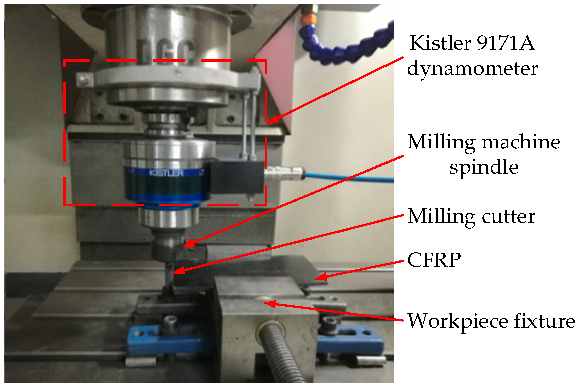
In order to compare the cutting performance of the diamond-coated rhombic milling cutter and the staggered helical one, the investigation of milling CFRP at high speed was designed in this paper. In the experiment, reverse milling was adopted, the Kistler 9171A dynamometer was directly fixed onto the VDL-1000E three-axis milling machine spindle, and the three-direction cutting forces in the milling were collected using the cutting force measurement and data acquisition system. The test site layout is shown in Figure 1. The experimental material was T700 multi-directional laminated CFRP composite panel made of AG-80 epoxy resin. Its specification was 200 mm × 110 mm × 5 mm and the fiber volume ratio was 60 ± 5%. The self-made rhombic milling cutter and staggered helical milling cutter were used in the experiment, and YG8 cemented carbide with 8% Co. was selected as the substrate material of the experimental cutting tools. The rhombic milling cutter includes a dextral cutting edge with a 15° helical angle and a sinistral cutting edge with a 40° helical angle, while for the staggered helical milling cutter, its sinistral and dextral cutting edges were both with a 6° helical angle, and the diameters of the two milling cutters are both 10 mm, as shown in Figure 2.
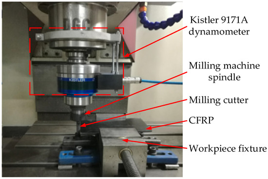
Figure 1.
The test site layout.

Figure 2.
Two styles of milling cutter, (a) the rhombic milling cutter and (b) the staggered helical milling cutter.
In the experiment, the cutting parameters were kept invariable, that is, the spindle speed was 3285 r/min, the cutting speed 100 m/min, the feed per tooth 0.02 mm/z, the cutting width 1 mm, and the cutting depth 5 mm. In order to observe the effect of tool wear on the machined surface quality, every time the milling proceeded 1 m away, the tool was removed to detect the wear state, and the machined workpieces with different tool wear stages were retained to facilitate the observation of the machined surface morphology. The machined surface morphology and the tool wear were measured using a VHX-1000 super-high magnification lens zoom three-dimensional (3D) microscope and SU3500 scanning electron microscope, respectively. Meanwhile, a Taylor Surface CCI white light interferometer was used to measure the workpiece surface roughness. The experiment was not stopped until obvious burrs occurred on the workpiece surface.
3. Results and Discussion
3.1. Analysis of Tool Wear
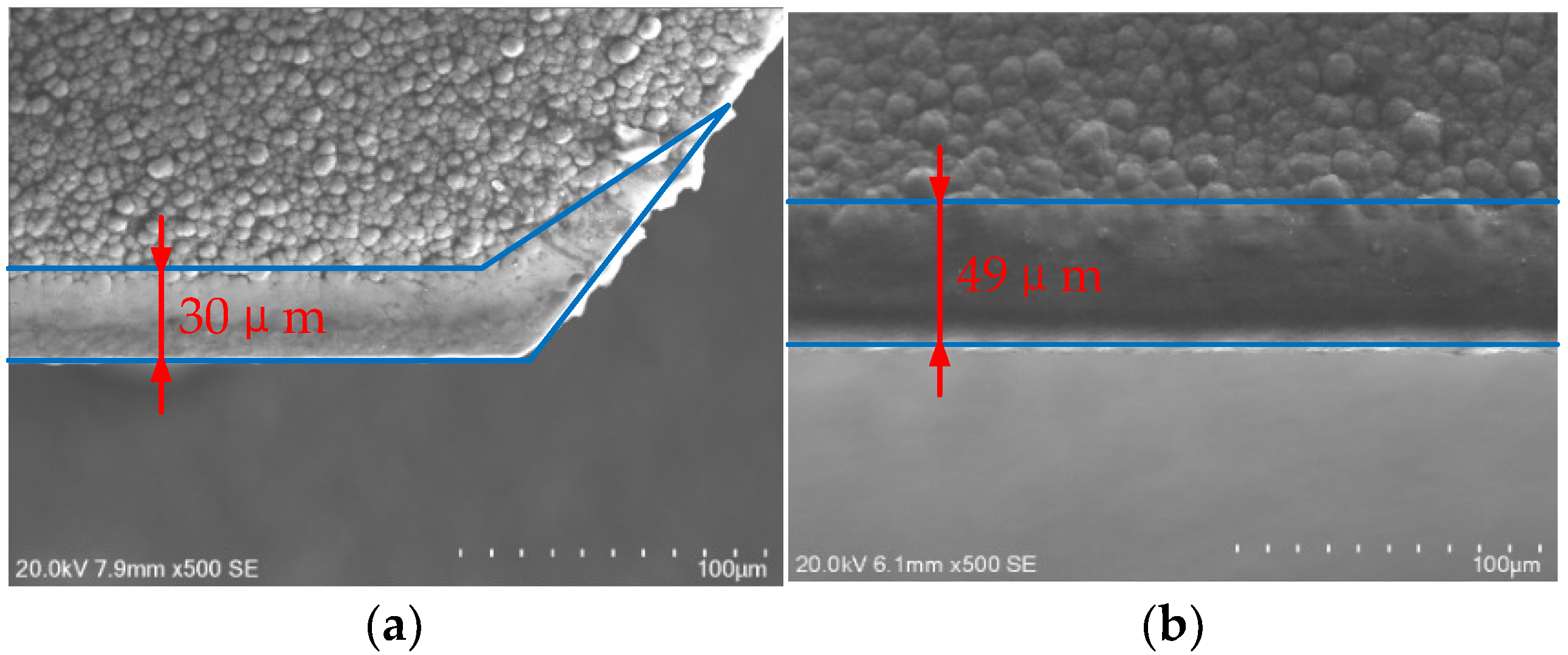
When the cutting speed was 100 m/min, for the two styles of milling cutters, both of their wear processes consisted of coating wear and coating shedding. In the initial milling, the tool wear was mainly the coating wear on the flank face. When the milling length was 12 m, the tool wear morphology of the two cutters, shown in Figure 3, mainly resulted from the effect of hard abrasive particles in carbon fiber materials.
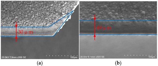
Figure 3.
The tool wear morphology when the milling length was 12 m, (a) the tool wear morphology of the rhombic milling cutter and (b) the tool wear morphology of the staggered helical milling cutter.
As shown in Figure 3a, for the rhombic milling cutter, the flank face of its dextral cutting edge demonstrated a uniform wear band, with the flank wear VB being about 30 μm, while at the tool tip of the rhombic teeth a triangular wear band occurred, mainly because only a part of sinistral cutting edge near the tool tip was involved in the milling. Nevertheless, as a result of the existence of the sinistral cutting edge, a chip-drain slot formed between the rhombic teeth, which was helpful for chip removal and heat dissipation. As shown in Figure 3b, for the staggered helical milling cutter, its flank face also showed an obvious wear band, with its flank wear VB being about 49 μm, due to the fact that the cutting edge of the staggered helical milling cutter was continuous, and the larger cutting load per cutting edge length resulted in a more significant cutting force and higher cutting temperature, and furthermore, it accelerated the flank wear.
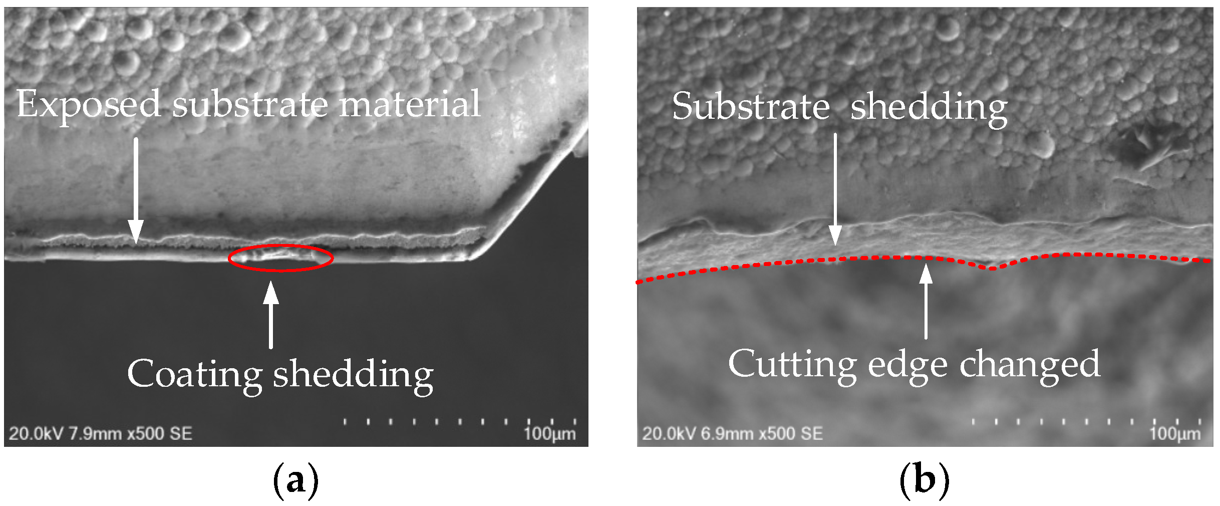
As the tool wear accelerated, the diamond coating on the flank face gradually got thinner, and the adhesion between the coating and the cemented carbide substrate decreased obviously, because of the effect of the frequent impact load and friction. For the staggered helical milling cutter, when the milling proceeded up to 33 m, cracks occurred on the coating at the cutting edge because of the effect of fatigue wear, and eventually, coating shedding was caused. At this moment, the tool wear transformed into the coating shedding from the coating wear. While for the rhombic milling cutter, coating shedding did not occur until the cutting proceeded up to 42 m. When the milling length reached 44 m, the two styles of cutting tools were both in the stage of coating shedding, as shown in Figure 4. Here, the flank face of the rhombic milling cutter demonstrated a small area of coating shedding, and the substrate material at the cutting edge was already exposed. Nevertheless, the cutting edge contour did not change obviously, and the cutting result was relatively good. By contrast, the staggered helical milling cutter showed a large area of coating shedding, and then formed an irregular tear wear band. At this point, the exposed cemented carbide substrate was already involved in cutting and fell off to a serious extent. As a result, the cutting edge changed into an irregular crescent shape from the original helical one.
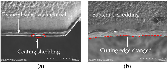
Figure 4.
The tool wear morphology when the milling length was 44 m, (a) the wear morphology of the rhombic milling cutter and (b) the wear morphology of the staggered helical milling cutter.
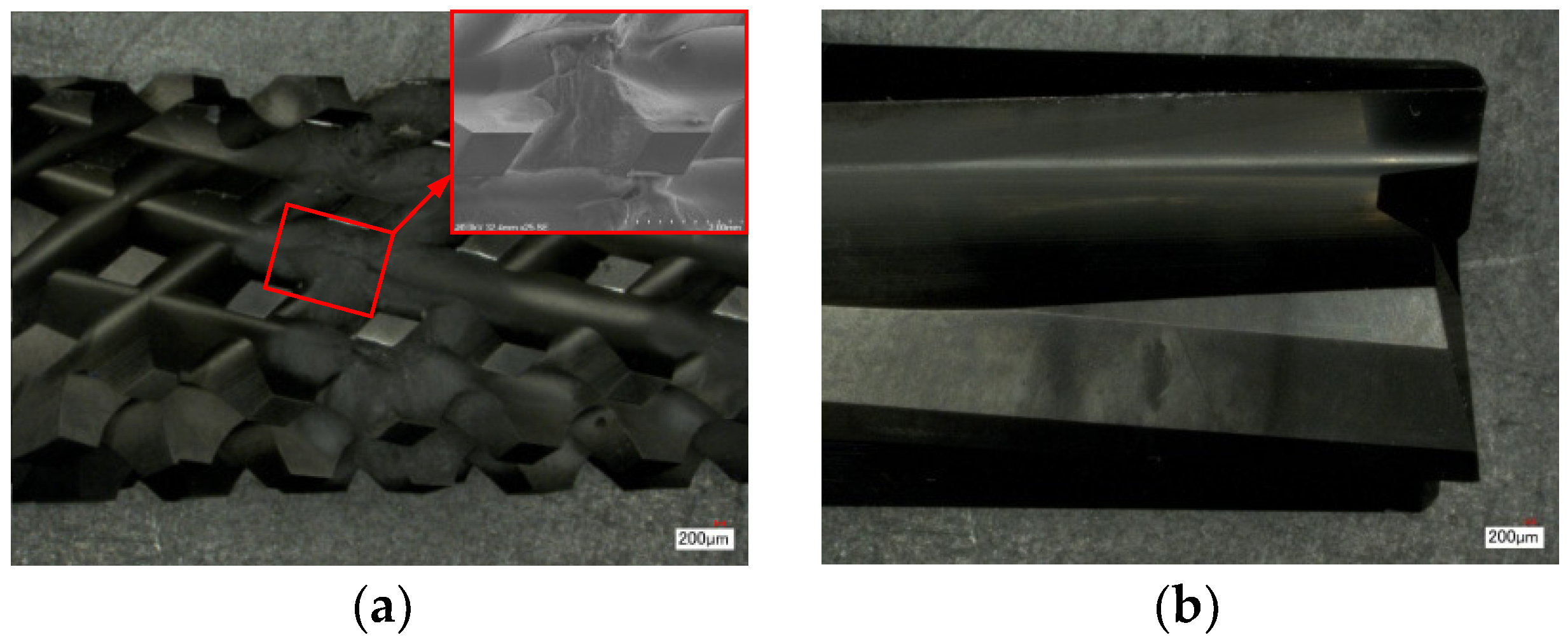
With the progression of milling, the diamond coating fell off more and more seriously. For the rhombic milling cutter, the cutting edge became obviously blunt, and thus it could not cut off the fibers effectively, which increased the heat generated in the cutting process. The occurrence of a large number of burrs at the edge of the machined surface, along with the small space of the chip-breaking groove, made it difficult to remove the broken burrs, so that they were adhered to and accumulated in the chip-drain slot, which caused an apparent blockage of chips, as shown in Figure 5. In contrast, for the staggered helical milling cutter, its large space of the chip-drain slot still maintained a superior ability to remove chips, even if the cutting edge was severely blunted.
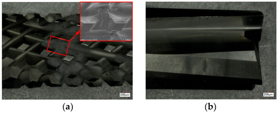
Figure 5.
The chip removal of the cutting tools when the coating fell off seriously, (a) the chip removal of the rhombic milling cutter and (b) the chip removal of the staggered helical milling cutter.
3.2. Effect of Tool Wear on Machined Surface Quality
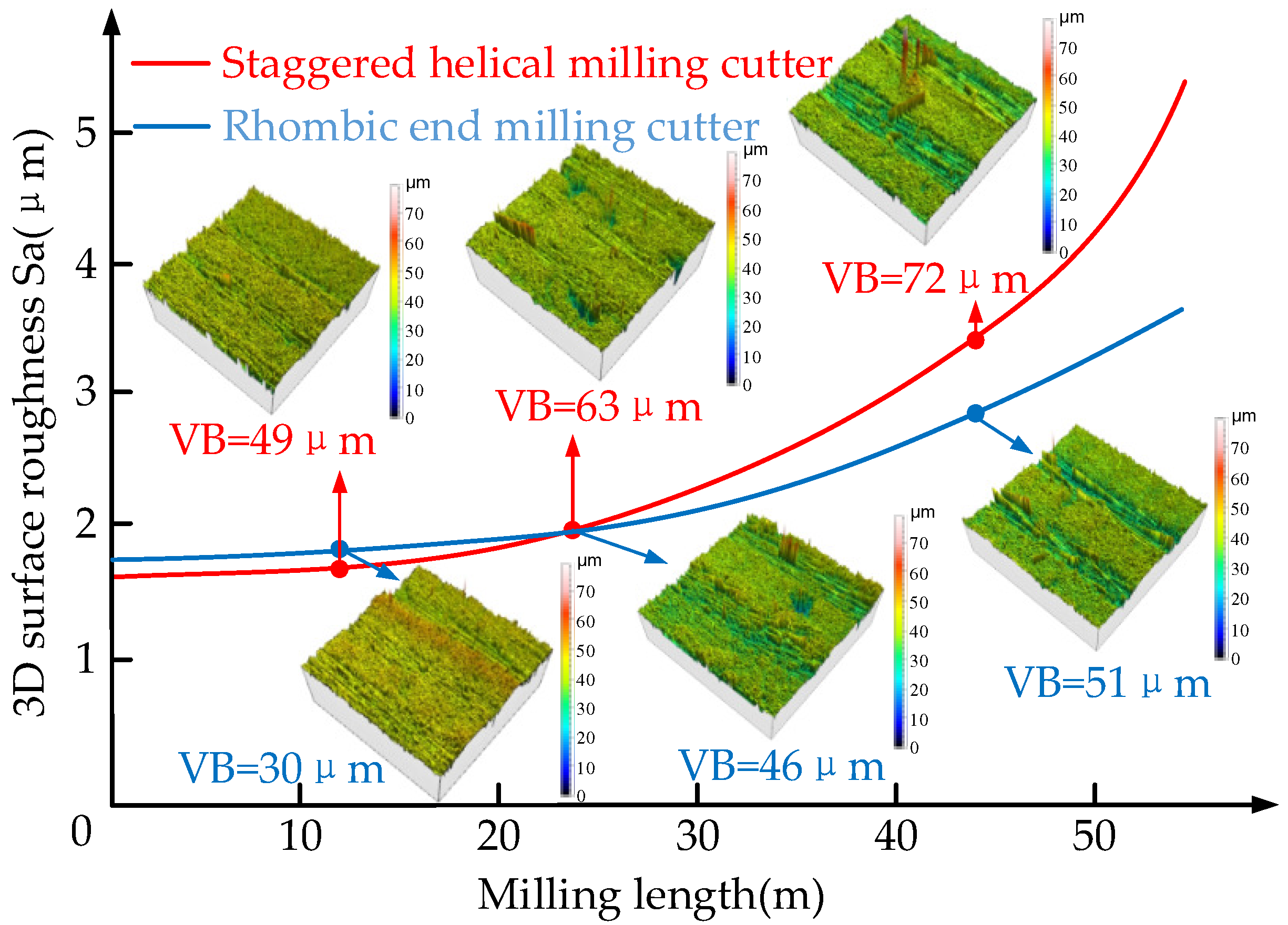
Figure 6 shows the surface roughness changes of the two styles of milling cutters with the condition of different milling lengths. When the milling length was less than 24 m, the staggered helical milling cutter was in the coating wear stage. Although the flank wear gradually increased, the machined surface morphology was still flat and regular, and of no obvious damage, and the machined surface roughness was less than that of the rhombic milling cutter. That is because a certain number of gaps between the segmented cutting edges of the rhombic milling cutter contributed to the fact that in the cutting of CFRP, some fibers were not cut off, and these unbroken fibers would be cut by sequent cutting edges. As a result, the residual height of the workpiece’s surface was increased, which finally caused the increase of the surface roughness.
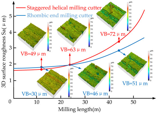
Figure 6.
The surface roughness changed with the difference of milling lengths.
With the development of milling, the flank wear of the rhombic milling cutter increased at a relatively slow speed. When the milling length was more than 24 m, the flank wear of the staggered helical milling cutter was more serious, and thus its surface roughness was already more than that of the rhombic milling cutter. Subsequently, the staggered helical milling cutter came into the coating shedding stage ahead of time, and here, the machined surface quality obviously decreased. When the milling length was more than 44 m, for the staggered helical milling cutter, its machined surface morphology was seriously deteriorated, the wave peak height rose sharply, and the groove area between the wave peak and trough obviously increased, while for the rhombic milling cutter, its wear resistance was good and its surface roughness grew slowly.
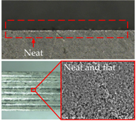
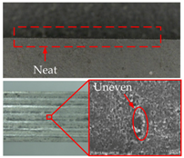
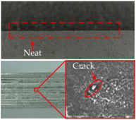
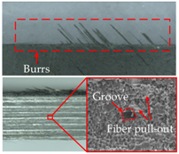
Table 1 shows the machined surface morphology of the two styles of cutting tools in different wear states. When the milling length was 12 m, the machined surfaces of the two cutting tools were both neat and flat, with no obvious burrs. When the milling length was 24 m, the machined surfaces of both of the cutting tools contained uneven positions, but there were no obvious defects or burrs. When the milling length reached 44 m, for the staggered helical milling cutter, its machined surface quality was seriously deteriorated. Defects such as lots of fiber pull-out, ravines, and local resin adhesions occurred, and a large range of dense burrs existed at the edge of the workpiece. In contrast, for the rhombic milling cutter, the wear state of the machined surface and edge was better than that of the staggered helical milling cutter, and the machined surface defects were mainly scratches and grooves with no resin adhesion being found.

Table 1.
The machined surface morphology in different milling lengths.
3.3. Effect of Tool Wear on Milling Force
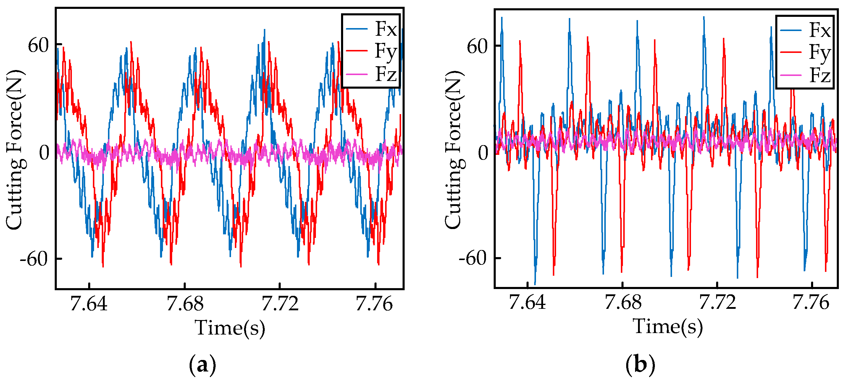
Figure 7 shows the measurement results of the cutting force in the milling CFRP with the two styles of cutting tools. It can be seen from the figure that for both styles of the cutting tools, the value of the axial cutting force was much smaller than that of both the feed cutting force and the radial cutting force. The stress of the rhombic milling cutter was more desirable, and its value was relatively small. However, the cutting force of the staggered helical milling cutter fluctuated in a larger range because of the larger impact effect.
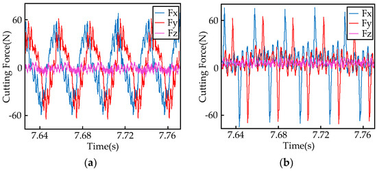
Figure 7.
The measurement results of cutting force in milling carbon fiber reinforced plastic (CFRP), (a) machining with the rhombic milling cutter and (b) machining with the staggered helical milling cutter.
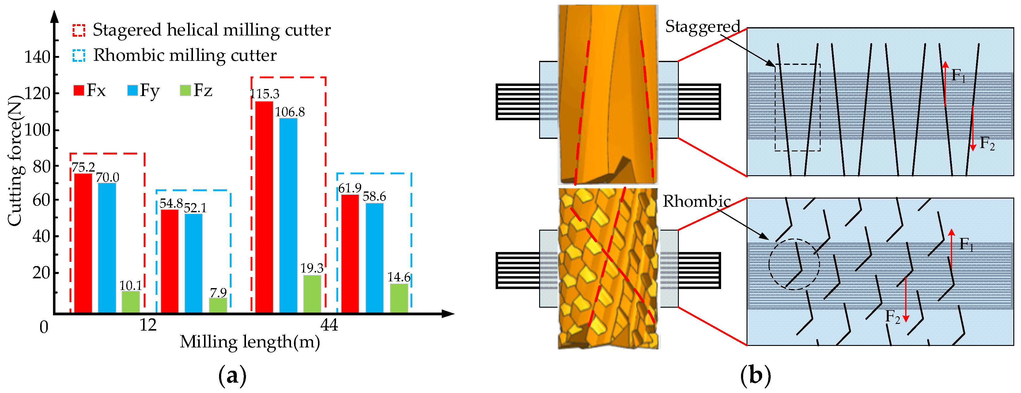
Figure 8a shows the comparison of the cutting forces in the milling carbon fiber composites with the two styles of cutting tools. It can be learned from the figure that with the aggravation of the tool wear, the three-directional cutting forces of the two cutting tools tended to change almost identically, that is, they all increased to a certain extent. Therein, the feed cutting force (Fx) and the radial cutting force (Fy) increased by a larger margin, while the axial cutting force (Fz) increased by a smaller margin. The cutting state analysis of the two milling cutters is shown in Figure 8b. When the milling length was 12 m, the three-directional cutting forces from the staggered helical milling cutter were all more than the ones from the rhombic milling cutter. That is because the cutting edge of the rhombic milling cutter consisted of multiple segments, which reduced the cutting load per unit of the cutting-edge length. As a result, the chip removal was smoother, and the friction between the chips and flank face largely decreased, and thus the cutting force obviously decreased. At this point, the axial forces produced by the two styles of milling cutters were both smaller. For one thing, the helical angle of the cutting edge took a decomposing role, and for another, the sinistral and dextral cutting edges produced a certain degree of counter action. When the milling length reached 44 m, the three-directional cutting forces of the staggered helical milling cutter increased more obviously. Here, the tool wear of the staggered helical milling cutter was more serious; its coating fell off in a large area and its cutting edge was obviously blunted. In addition, its cutting mechanism transformed into extrusion from the original shearing, which greatly increased the resistance in the cutting process.
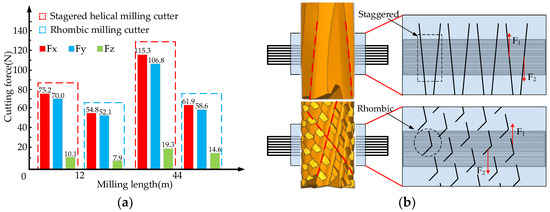
Figure 8.
The analysis of cutting force and state of two kinds of milling cutters, (a) cutting forces measurement with the cutting length being 12 m and 44 m, respectively, and the (b) comparison of the cutting state in milling CFRP with the two styles of cutting tools.
4. Conclusions
- In the coating wear stage, compared with the rhombic milling cutter, the staggered helical milling cutter has alternately arranged continuous cutting edges, which makes the machined surface quality better. However, its wear resistance was relatively weak and the flank wear rate was relatively fast, and thus the scratches in the wear area were more obvious.
- The coating shedding of the staggered helical milling cutter occurred earlier, and thus its cutting edge shape obviously changed with the wear of the substrate material. With the occurrence of damage such as fiber pull-out, tears, burr, and so on, the machined surface quality subsequently decreased.
- When coming into the coating shedding stage, the surface roughness of the rhombic milling cutter grew more slowly. The serious damage did not occur on the machined surface until a large area of the coating fell off. At this time, the chip removal performance of the cutting tool gradually decreased, and obvious chip blockage existed.
- Compared with the staggered helical milling cutter, the rhombic milling cutter could obviously decrease the feed cutting force and the radial cutting force, and even in the condition of tool wear, the three-direction cutting forces increased more slowly. In addition, the axial cutting forces from the two styles of cutting tools were both smaller, and fluctuated only in a small range.
Author Contributions
T.C. and F.G. designed the tool and experiment. F.G. and S.L. performed the experiment. S.L. and X.L. analyzed the data. T.C., S.L., and F.G. wrote the paper.
Funding
“This research was funded by [National Natural Science Foundation of China] grant number [51475125]” and by [Natural Science Foundation of Heilongjiang Province] grant number [E2016047]”.
Conflicts of Interest
The authors declare no conflict of interest.
References
- Gordon, S.; Hillery, M.T. A review of the cutting of composite materials. Proc. Inst. Mech. Eng. Part L J. Mater. Des. Appl. 2003, 217, 35–45. [Google Scholar] [CrossRef]
- Maegawa, S.; Morikawa, Y.; Hayakawa, S. Mechanism for changes in cutting forces for down-milling of unidirectional carbon fiber reinforced polymer laminates: Modeling and experimentation. Int. J. Mach. Tools Manuf. 2016, 100, 7–13. [Google Scholar] [CrossRef]
- Abena, A.; Soo, S.L.; Essa, K. A Finite Element Simulation for Orthogonal Cutting of UD-CFRP Incorporating a Novel Fibre-matrix Interface Model. Proc. Cirp. 2015, 31, 539–544. [Google Scholar] [CrossRef]
- Mathivanan, N.R.; Mahesh, B.S.; Shetty, H.A. An experimental investigation on the process parameters influencing machining forces during milling of carbon and glass fiber laminates. Measurement 2016, 91, 39–45. [Google Scholar] [CrossRef]
- Zhou, X.H.; Sun, Y.S.; Wang, W.S. Influences of carbon fabric/epoxy composites fabrication process on its friction and wear properties. J. Mater. Process. Technol. 2009, 209, 4553–4557. [Google Scholar] [CrossRef]
- El-Hofy, M.H.; Soo, S.L.; Aspinwall, D.K.; Sim, W.M.; Pearson, D. Factors Affecting Workpiece Surface Integrity in Slotting of CFRP. Proc. Eng. 2011, 19, 94–99. [Google Scholar] [CrossRef]
- Isbilir, O.; Ghassemieh, E. Finite element analysis of drilling of carbon fibre reinforced composites. Appl. Compos. Mater. 2012, 19, 637–656. [Google Scholar] [CrossRef]
- Ghoreishi, R.; Roohi, A.H.; Ghadikolaei, A.D. Analysis of the influence of cutting parameters on surface roughness and cutting forces in high speed face milling of Al/SiC MMC. Mater. Res. Express 2018. [Google Scholar] [CrossRef]
- Gopal, P.M.; Prakash, K.S. Minimization of cutting force, temperature and surface roughness through GRA, TOPSIS and Taguchi techniques in end milling of Mg hybrid MMC. Measurement 2018, 116, 178–192. [Google Scholar] [CrossRef]
- Teng, X.Y.; Chen, W.Q.; Huo, D.H.; Shyha, I.; Lin, C. Comparison of cutting mechanism when machining micro and nano-particles reinforced SiC/Al metal matrix composites. Compos. Struct. 2018, 203, 636–647. [Google Scholar] [CrossRef]
- Khairusshima, M.K.N.; Sharifah, I.S.S. Study on Tool Wear during Milling CFRP under Dry and Chilled Air Machining. Proc. Eng. 2017, 184, 506–517. [Google Scholar] [CrossRef]
- Jia, Z.; Su, Y.; Niu, B.; Bai, Y.; Bi, G. Deterioration of polycrystalline diamond tools in milling of carbon-fiber-reinforced plastic. J. Compos. Mater. 2016, 51, 2277–2290. [Google Scholar] [CrossRef]
- Slamani, M.; Chatelain, J.F.; Hamedanianpour, H. Comparison of two models for predicting tool wear and cutting force components during high speed trimming of CFRP. Int. J. Mater. Form. 2015, 8, 305–316. [Google Scholar] [CrossRef]
- Karpat, Y.; Polat, N. Mechanistic force modeling for milling of carbon fiber reinforced polymers with double helix tools. CIRP Ann.-Manuf. Technol. 2013, 62, 95–98. [Google Scholar] [CrossRef]
- Chen, L.; Zhang, K.; Cheng, H.; Qi, Z.; Meng, Q. A cutting force predicting model in orthogonal machining of unidirectional CFRP for entire range of fiber orientation. CIRP Ann.-Manuf. Technol. 2016, 89, 1–14. [Google Scholar] [CrossRef]
- Ghafarizadeh, S.; Chatelain, J.F.; Lebrun, G. Finite element analysis of surface milling of carbon fiber-reinforced composites. Int. J. Adv. Manuf. Technol. 2016, 87, 1–11. [Google Scholar] [CrossRef]
- Hintze, W.; Brügmann, F. Influence of spatial tool inclination on delamination when milling CFRP. J. Mater. Process. Technol. 2018, 252, 830–837. [Google Scholar] [CrossRef]
- Pecat, O.; Rentsch, R.; Brinksmeier, E. Influence of milling process parameters on the surface integrity of CFRP. Proc. Cirp. 2012, 1, 466–470. [Google Scholar] [CrossRef]
- Çolak, O.; Sunar, T. Cutting Forces and 3D Surface Analysis of CFRP Milling with PCD Cutting Tools. Proc.Cirp. 2016, 45, 75–78. [Google Scholar] [CrossRef]
- Chen, T.; Gao, F.; Li, S.Y.; Liu, X.L. Experimental Study on Cutting Tool Wear in Milling Carbon Fiber Composites with Spiral Staggered Diamond-coated Milling Cutter. Int. J. Adv. Manuf. Technol. 2018. [Google Scholar] [CrossRef]
© 2018 by the authors. Licensee MDPI, Basel, Switzerland. This article is an open access article distributed under the terms and conditions of the Creative Commons Attribution (CC BY) license (http://creativecommons.org/licenses/by/4.0/).

