Abstract
In this paper, we present a solution for the photorealistic ambient light render of holograms into dynamic real scenes, in augmented reality applications. Based on Microsoft HoloLens, we achieved this result with an Image Base Lighting (IBL) approach. The real-time image capturing that has been designed is able to automatically locate and position directional lights providing the right illumination to the holograms. We also implemented a negative “shadow drawing” shader that contributes to the final photorealistic and immersive effect of holograms in real life. The main focus of this research was to achieve a superior photorealism through the combination of real-time lights placement and negative “shadow drawing” shader. The solution was evaluated in various Augmented Reality case studies, from classical ones (using Vuforia Toolkit) to innovative applications (using HoloLens).
1. Introduction
Augmented Reality (AR) is capable of inserting virtual objects into real world environments. There are many cases where AR is helpful in industrial applications, but usually it lacks in visual quality because the image shown is poor. For this reason, rendered images of products are visualized on screens because the visual quality is much greater and the use of AR technology is limited only to essential situations [1]. Low visual quality of AR objects can be considered a not problem when information to be delivered to the user are instructions or technical information: in this case, the main focus of the AR tool is to dispatch a precise information, not a realistic one. On the other hand, low visual quality of AR objects becomes a problem when the main objective of the AR tool is to create the sense of immersiveness to the user. In such cases, the low visual quality problem can be divided into two sub-problems: the material problem and the light problem. The material problem has been faced with the introduction of rendering pipelines, for example the new High Definition Rendering Pipeline in Unity 2018.1, and the implementation of high defined materials with several types of maps, normal map, bump map, specular map, etc., which produce more realistic materials. However, even with the use of ultra realistic materials, watching an AR object casting no shadow fails the scene realism. The realism of the scene is crucial in all those applications that aim to engage the user and to enhance user experience more than to provide the user with technical information or instructions, for example: design review, customer customization and press release. In such a way, matching the environment lighting scheme with the synthetic lighting scheme is fundamental.
2. State of the Art
To ensure a realistic experience in AR and Virtual Reality (VR), several requirements must be met, for example a correct and stable pose of the objects with respect to the user’s view, an intuitive interaction with the holograms and a high frame rate to ensure fluidity to the stream. In recent years, most research has been done to improve tracking system for AR applications [2,3,4] and also the calculating power of AR devices has increased. Due to these achievements, visual quality of the augmented objects began to gain importance in the realism of the AR simulations: in fact, even if the augmented 3D models are posed with extreme precision and tracked with high frame rate, their visual quality reveals they are artificial. This happens because the simulation of environment lighting is poor and weak.
There are of course many cases where this realism is not necessary, but could make the job more immersive [5,6]. In VR applications, the principal requirement is the sense of presence, the power for the graphics user believe he is in an environment that does not exist. Lighting has the big task of making that happen. Instead, for AR application, lighting has the task of seamlessly inserting synthetic model in the scene. To do this, virtual lighting of 3D objects has to match the lighting of the surrounding environment in order to create the illusion of real objects. Moreover, this process must be as rapid and automated as possible, in order to be performed by not skilled users and to ensure a high frame rate. Available techniques for realistic real-time rendering of objects are usually characterized by long setting time and they are not always successful. Generally, the set-up is manually made and pre-calculated. This way, the position, color and intensity of virtual light sources are different in any environment and an automated standalone application cannot be used. Another technique consists in using a photo of a reference object, for example a grey sphere, previously taken in the environment, and use its appearance to manually set up the lightning conditions. Nevertheless, the problem of manually configuring the lightning environment remains. Paul Debevec [7] firstly proposed to use a set of photographs of a reflective sphere with different exposures in order to reconstruct the lighting scheme of the environment. This method has effective results but requires a physical support and a great computational effort, not suitable for real-time rendering. In [8], the authors proposed a real-time lighting acquisition procedure that computes the lights pose using a diffuse sphere, a ping pong ball, and it is rapid enough to guarantee real-time renderings. However, this method also requires a physical support. In [9], the authors developed a pipeline for rendering and lighting augmented objects over planar surfaces. The process does not manage environment lighting changes, thus it is not suitable for real-time application. In [10], the authors proposed the use of HDR images to deduce environment radiance values and to project them onto a 3D geometry reconstruction of surrounding environment. This process is totally probeless, since is based on HDR images but requires a server-client data exchange. Moreover, the environment geometry and objects materials of the scene are manually reconstructed, thus this process is tedious and time-consuming. In addition, in [11], the authors proposed the use of a probe in order to reconstruct the environment map and estimate light source direction as well as focused on the algorithm of shadows creation. Our method instead is probeless, as mentioned above, and we did not concentrate on the shadow creation algorithm, because we rely on the Unity built-in shadow method, while we faced the problem of creating the shadow onto a transparent screen. Moreover, the proposed method does not require calculating the light source position every frame, but only once at the beginning of the AR session or, if necessary, when the environment lighting scheme is drastically changed. In [12], the authors proposed the use of RGBD camera to solve the problem of ahead geometry reconstruction of surrounding environment. Thanks to voxel reconstruction executed by RGBD camera, it is possible not just to estimate the environment illumination but to cast shadows of real geometry onto virtual objects. However, their solution is based on Microsoft Kinect, hence it requires a stationary PC.
Starting from this solution, we propose a method which overcomes the weaknesses of previous approaches. Differently from Debevec’s solution and others, our method does not require a physical support. Moreover, the main objective of the proposed pipeline is to be highly automated and to require modest computational effort, in order to be implemented in real-time applications. Thanks to its implementation in HoloLens, it is standalone and can be employed in different scenarios. For example, it can be used for design revision and product configuration in order to make the client deeper involved in the design process. Another application could be in tourism and archeology in order to enhance user’s experience. Lastly, it can be implemented in video games. In this paper, we describe our pipeline ARPAS (Augmented Reality Photorealistic Ambient Shadows), for the acquisition of the lighting scheme of surrounding environment and his implementation to the AR scene. Our pipeline is appropriate for AR applications using Optical See-Through (OST) Head Mounted Displays (HMD) where 3D models are overlaid directly in the real world, hence in applications where realism of augmented objects must be as high as possible.
3. Proposed Solution
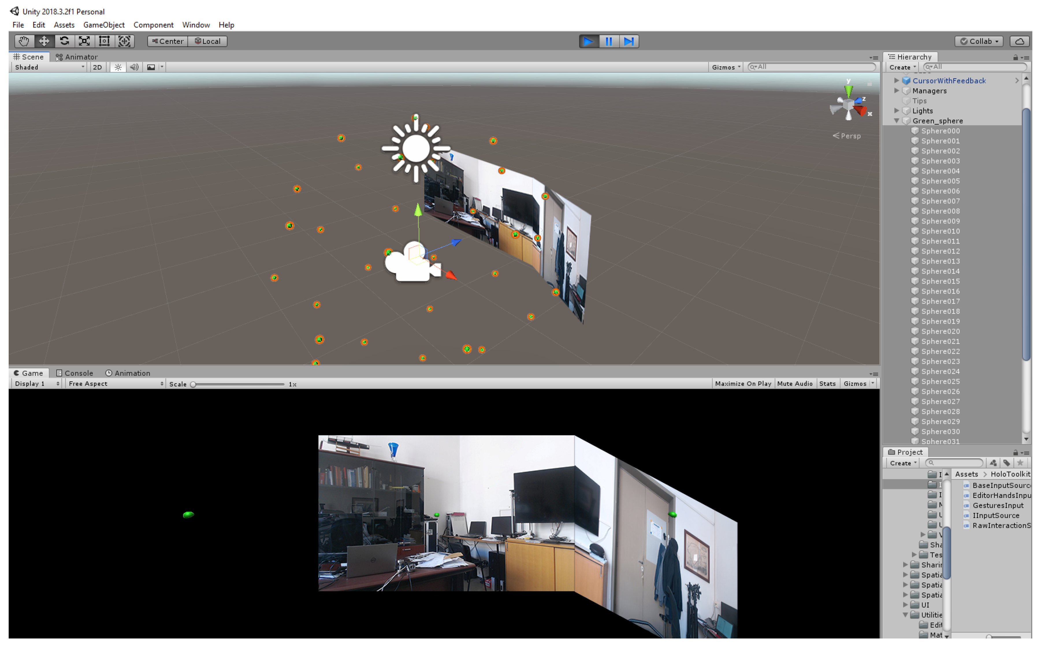
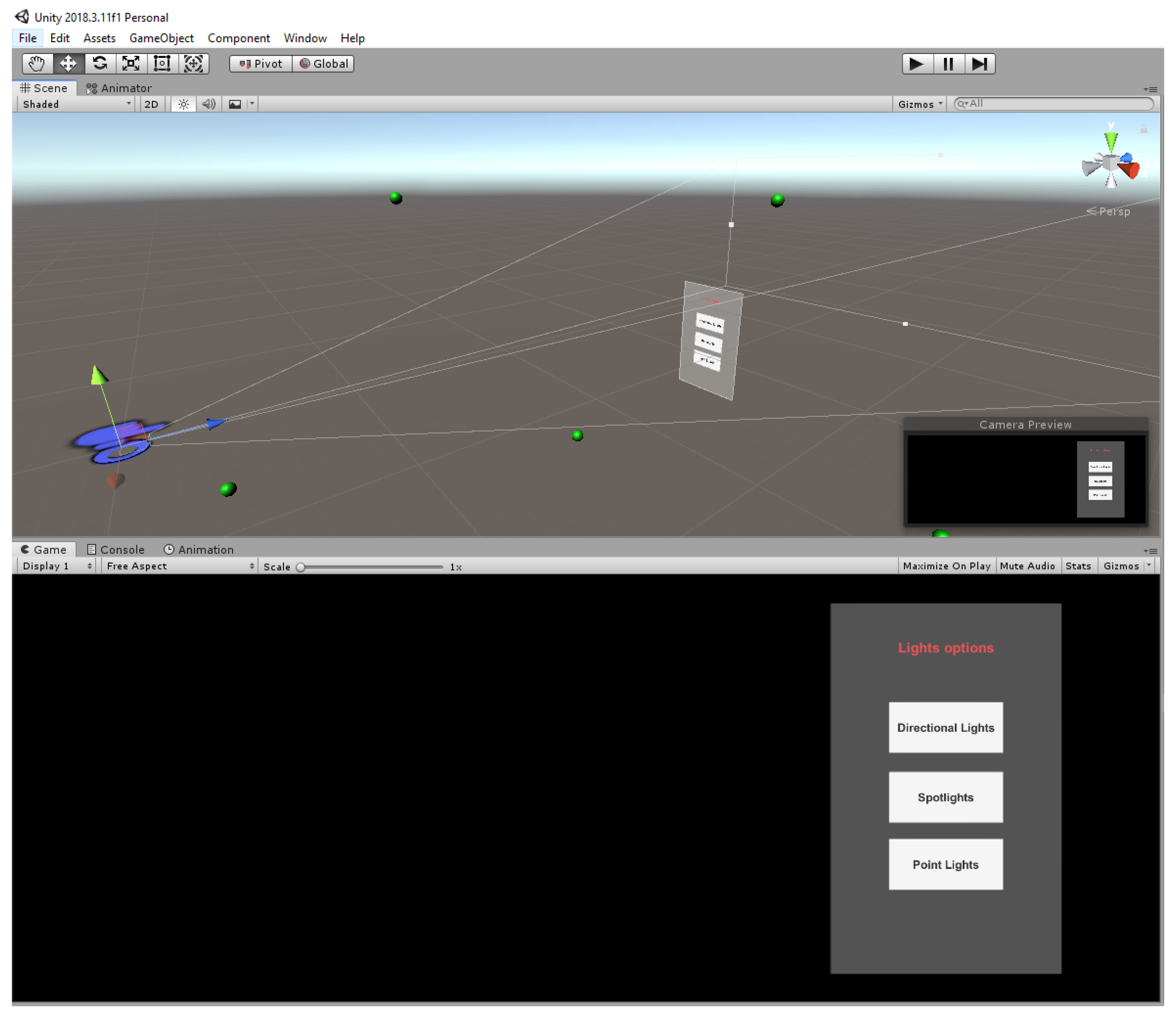
ARPAS aims to recover from an HDR and LDR image information regarding the global illumination of the environment and any light sources present around the user. Capturing and measuring light: this process gives the so-called light probe images. The images composing the light probe must have two features: firstly, they must be omnidirectional, i.e., for each direction of the space, there is a pixel representing that direction; and, secondly, the pixel values correspond with the amount of light coming from that direction. To satisfy the omnidirectionality characteristic, the most used method is to photograph a mirror sphere: this method allows acquiring the light coming from behind the sphere, since the rays behind the sphere are diverted and captured by the camera from the front. A simpler method is to take several photos of the whole environment and to compose them together, overlapping them, to form a spheremap. We implemented the spheremap method in our application as a pre-set scene. In the pre-set scene, the user takes several photos of the environment and the application automatically composes them to create the spheremap. The pre-set scene UI helps the user to take equidistant photos of the environment thanks to 34 targets, i.e., the green spheres (Figure 1) placed in every sector. These targets change color when the photo is taken and saved. This expedient prevents to take multiple photos of the same sector.

Figure 1.
Spheremap creation in Unity pre-set scene.
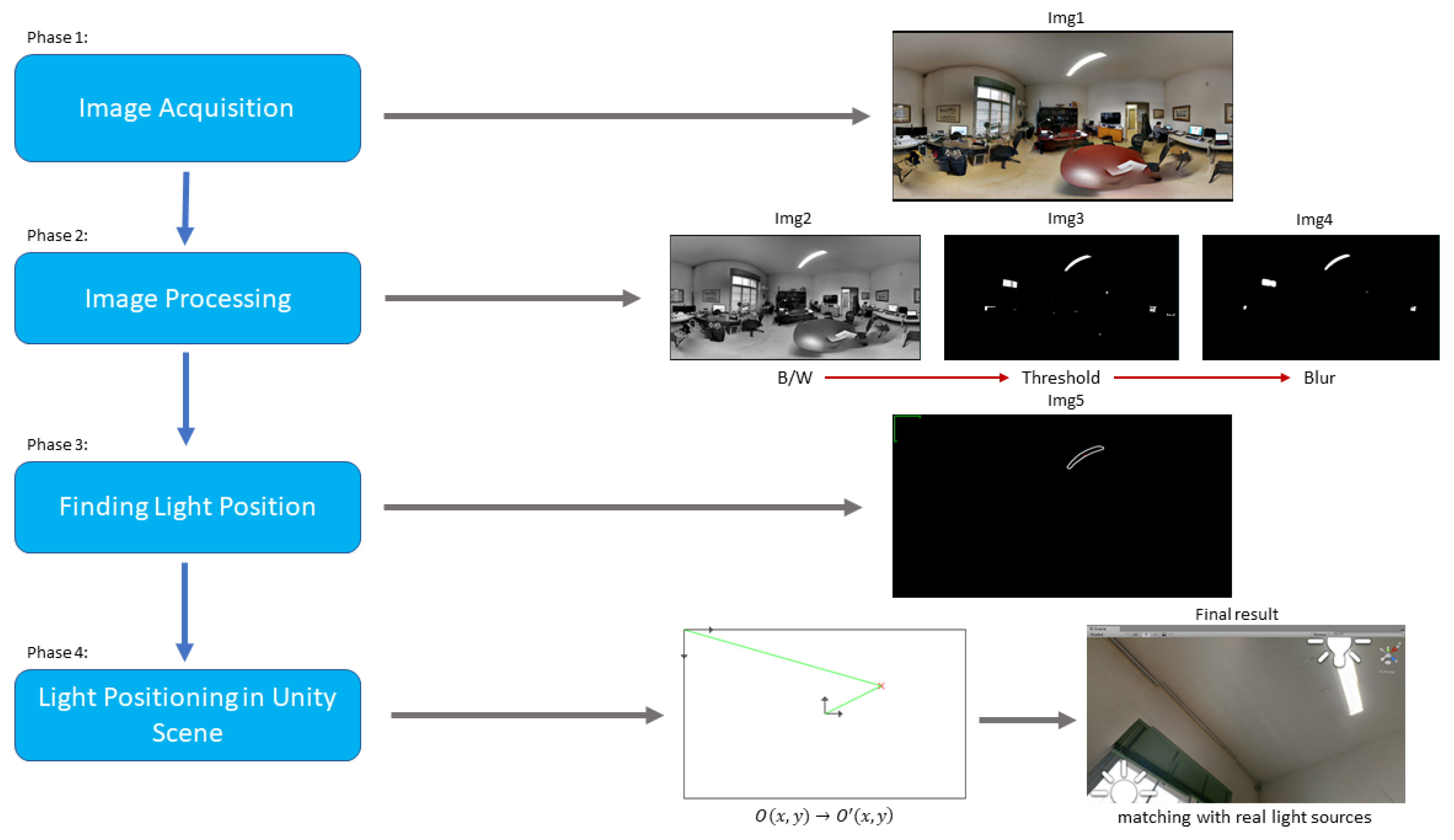
Moreover, the application reference system is set at the startup so the spheremap and the environment mesh are completely overlaid. In this way, it is possible to illuminate a virtual object positioned in the environment with the realistic lighting scheme and, at the same time, to simulate occlusions, reflections and shadows. An image analysis process has been implemented to extrapolate, in an accurate and stable way, the position of one or more direct light sources for the position of the corresponding virtual ones in the Unity scene. The logic map applied for this scope is represented in (Figure 2).

Figure 2.
Logical map ARPAS.
Four main steps are presented:
- Image Acquisition
- Image Processing
- Finding Light Position
- Light Positioning in Unity Scene
The project starts from the acquisition of the original image through the filtering stages until the positioning of lights in the Unity scene and it finishes in a comparison with the reality matching the results.
3.1. Image Acquisition
The first step was to generate and save the 360 degree spherical image within HoloLens internal storage. This image was created with the above mentioned pre-set scene (Figure 3). Moreover, it is important to notice that this step can be repeated: any time the user wants, he can return to the pre-set scene and create a new spheremap with a new set of photos. This feature makes our method suitable for highly portable and real-time applications.

Figure 3.
360-degree spherical image.
3.2. Image Processing
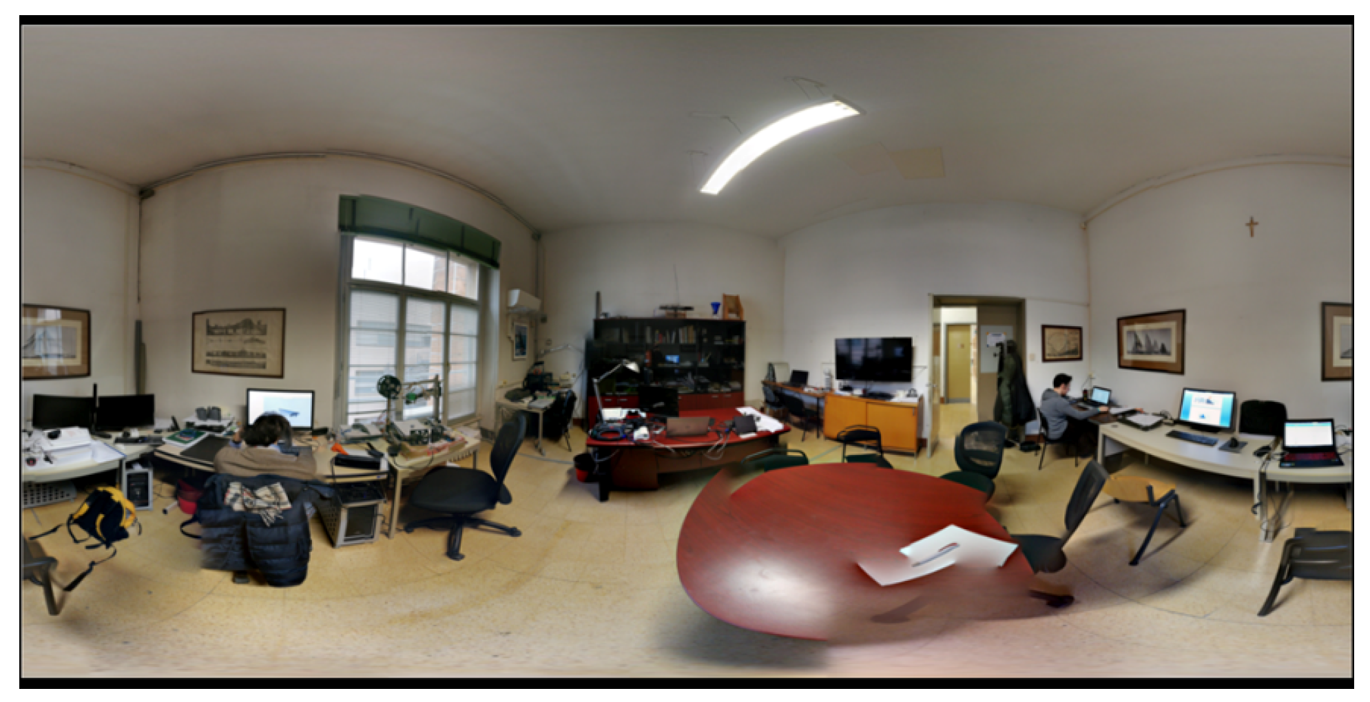
OpenCV computer vision library is necessary for the image processing pipeline. Since it was written in C++, the program for the recovery of the light source position was first developed and tested in a standalone mode and then integrated as a dynamic-link library (.dll) into Unity. It was chosen to create a specific .dll instead of using a wrapper, such as “Emgu CV” or “OpenCV for Unity” because they are not free for Unity. Moreover, our purpose was to create a standalone package including only the necessary functions and referring to the major installation of OpenCV on the computer, hence the multi-platform capability of adding OpenCV to a specific path of the system. The light detection routine applies a sequence of filters, thresholds and algorithms. Firstly, the 360 degree spherical image is converted from RGB to B/W, since the final scope is to recognize light sources that tend to be white and to have a high level of brightness (Figure 4). Moreover, the conversion of the 360-degree spherical image from RGB to B/W makes it easier to apply a threshold value to the pixels color values since they vary only from 0 to 255. After the greyscale conversion, it is possible to apply a threshold value to the image in order to delete all the pixels with color value below the given threshold. This threshold is chosen by analyzing the image histogram (Figure 5). In the first step, the maximum value of pixels was found. It is important to notice that not every photography covers the entire range of 0–255 such as too dark or too bright images. After the definition of the spectrum, it was possible to calculate the average value of pixels. The imposition we made was the definition of the ratio of these two values:
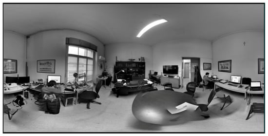
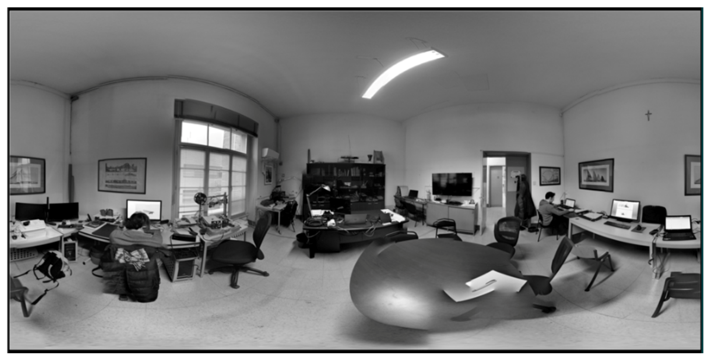
Figure 4.
Greyscale conversion.
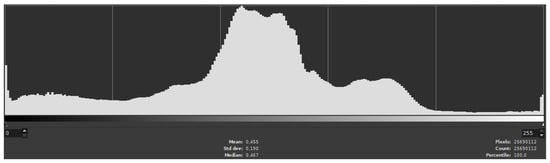
Figure 5.
Histogram of the office room sphere map case study.
If this condition is true, it means that the distance between the maximum value and the average value of pixels is enough to state that there is a visible difference between the ambient light and a possible point light.
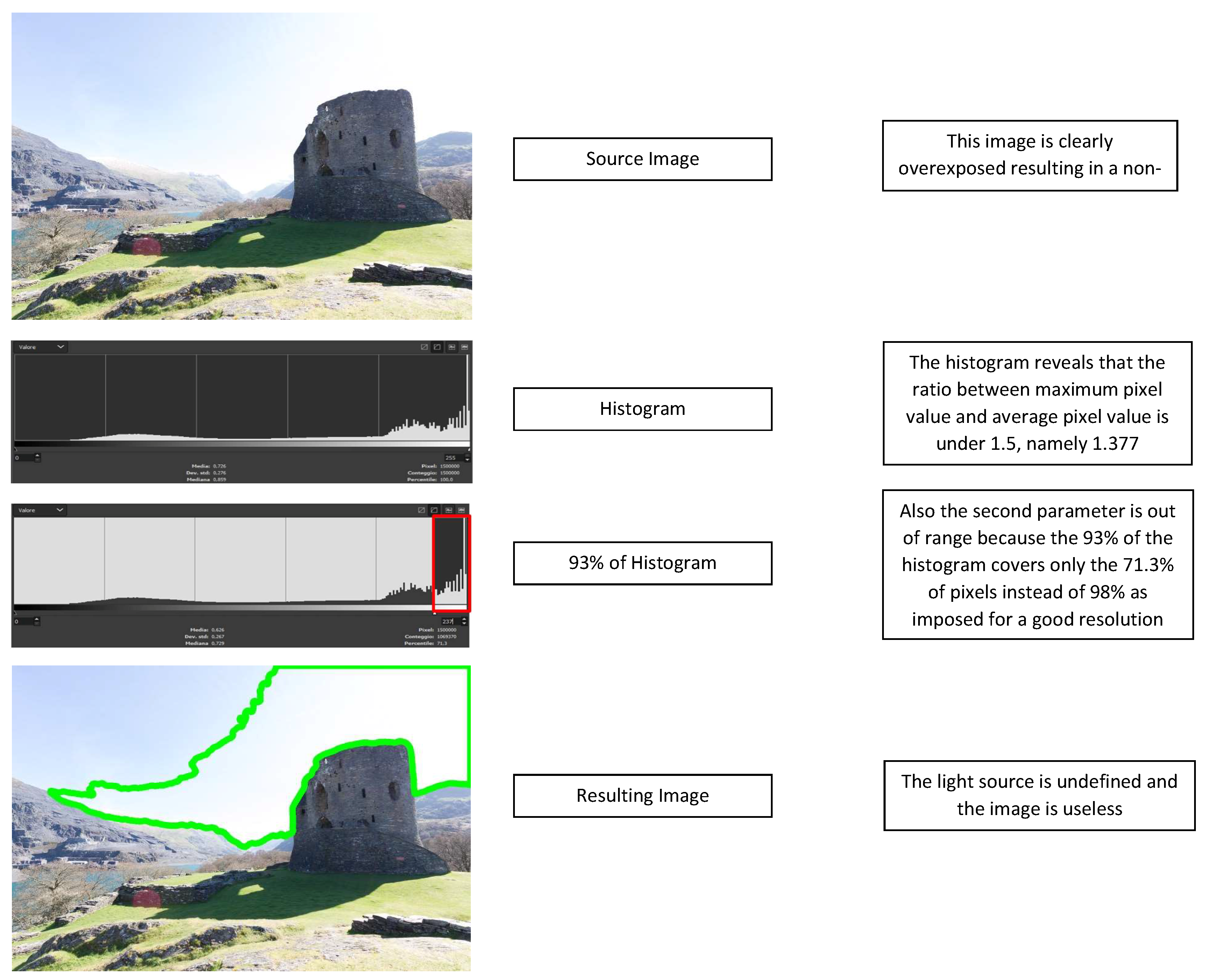
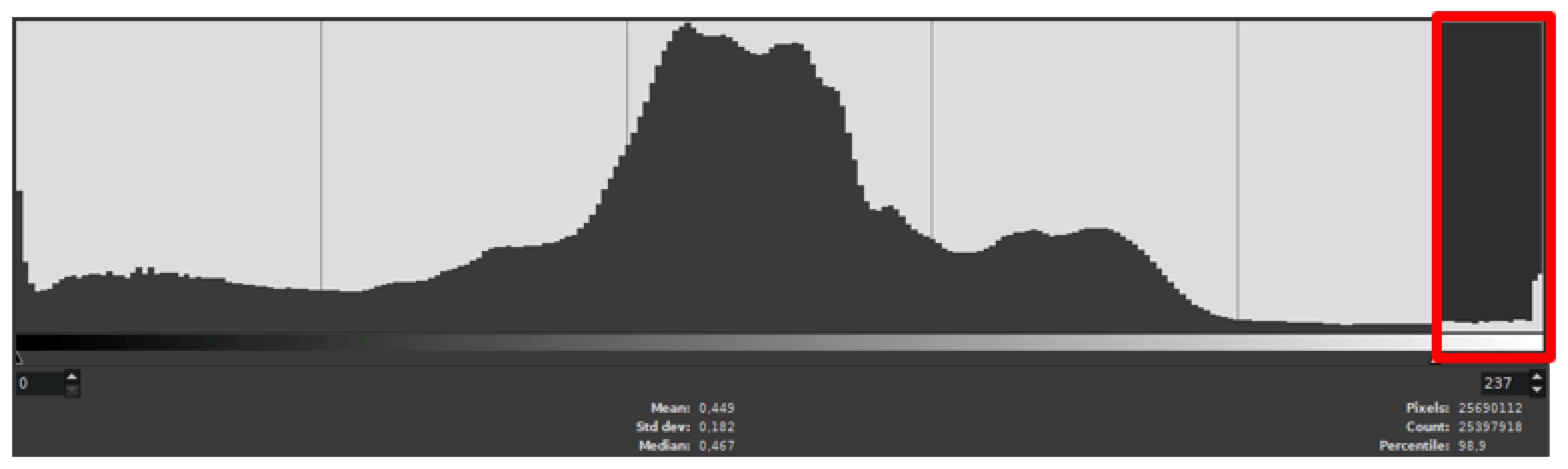
Therefore, a ratio of 1.5–1 makes the photography useless, because in this condition it is possible to misidentify ambient light with point light, resulting, firstly, in a too high density of white pixels and, secondly, in an inaccurate positioning of the light in the method second step. (Figure 6). Contrariwise, if the ratio is over 1.5, as shown in Figure 5, where the value is 2.197, the correct positioning of the light source is achieved. In the second step. the estimation of threshold value was made. If 93% of the spectrum (starting from 0) covers at least 98% of the pixels, then it is possible to threshold the remaining 7% (Figure 7). This step allows cutting out the image and considering only the areas of the image corresponding to the actual light sources (Figure 8). At this point, only the brightest areas remain and they correspond to the room chandelier, the window and PC monitors. For this fist example, we decided to identify the area with the brightest intensity and to assign to this area the task of being the only light source of the scene. A median blur filter (Figure 9) was applied as noise reduction technique since it is possible that there are some areas with pixels value above the threshold value due to reflections of the objects in the environment. Using other types of filters, for example erode and dilate filters, provides the same result but with two or more sequential operations, instead of one single operation as in the case of median blur implementation.
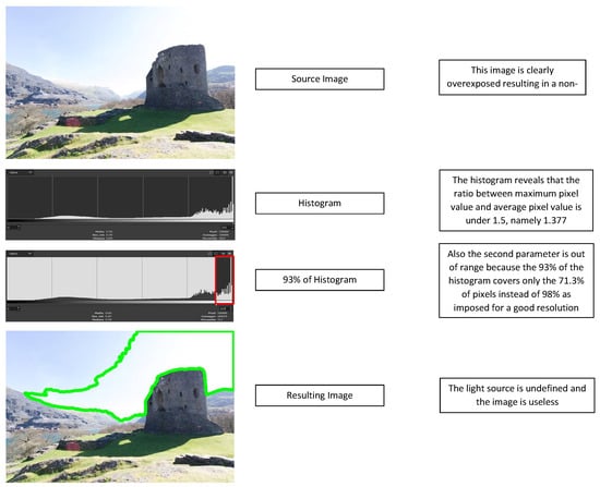
Figure 6.
Example of an overexposed image not suitable for the proposed method.
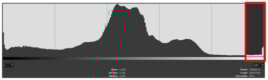
Figure 7.
Ninety-three percent of the entire spectrum covers 98.9% of pixels.
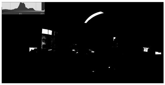
Figure 8.
Image thresholding.
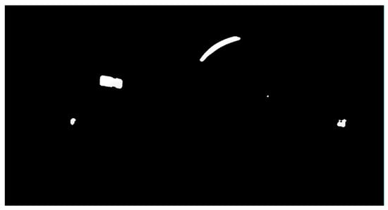
Figure 9.
Median blur filter application.
3.3. Finding Light Position
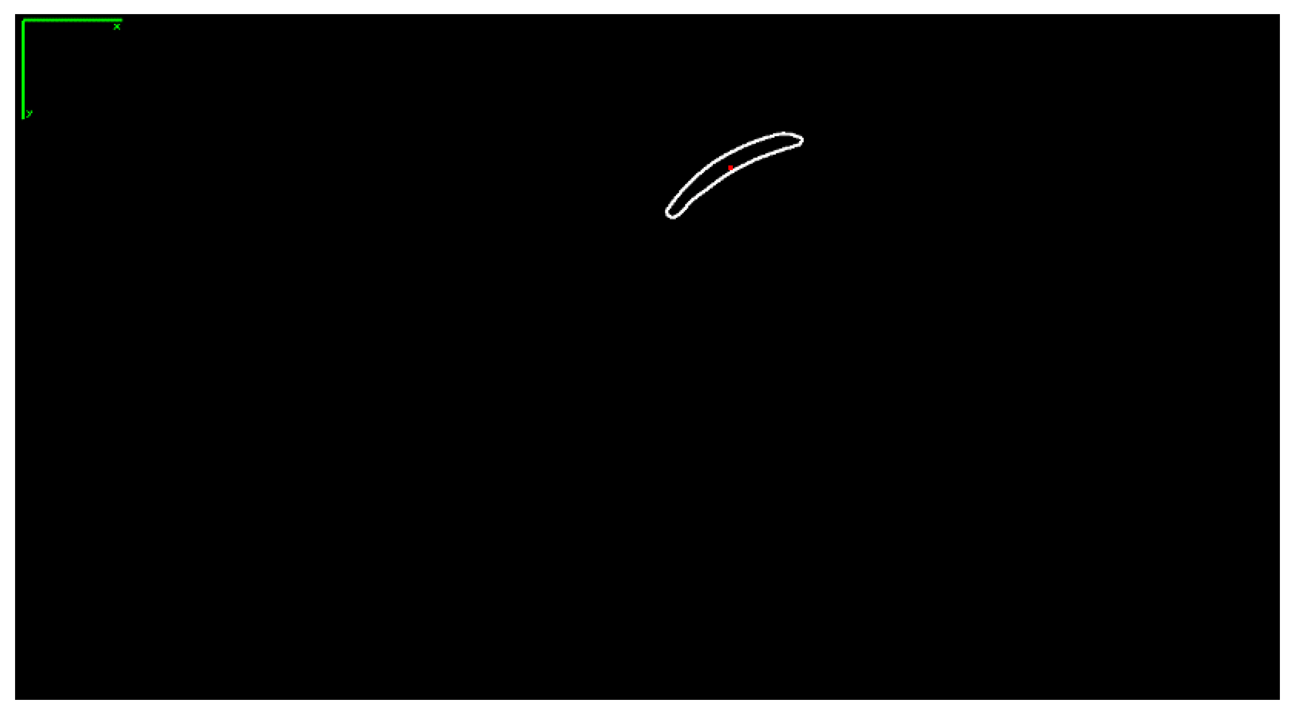
Using the OpenCV function “cv::findContours”, it was possible to identify the contours of the different light sources. After that, the function “cv::moments” was used to calculate the moments of the surrounded light sources. From these moments, useful data such as area and centroid could be extracted. For this reason, the implementation of the function “cv::moments” was preferred to the function “cv::contuorArea”, which provides less information. Finally, the contour and the COG of the greatest area was positioned with respect to the reference system (Figure 10). For this example, we decided to delete all the areas except for the greatest one corresponding to the chandelier.
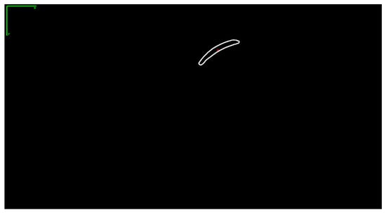
Figure 10.
Contour and COG of the greatest light source.
3.4. Parameters Validation
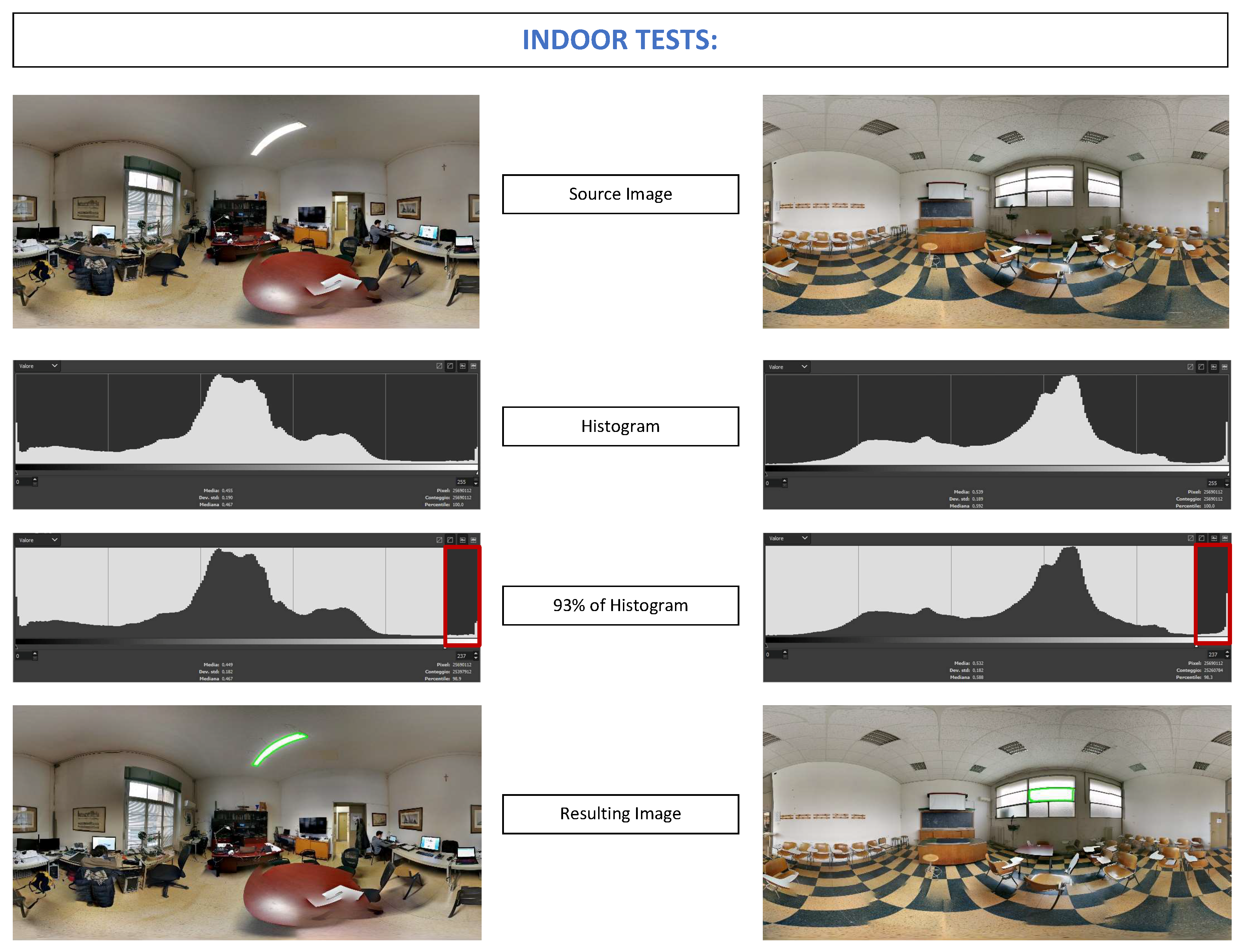
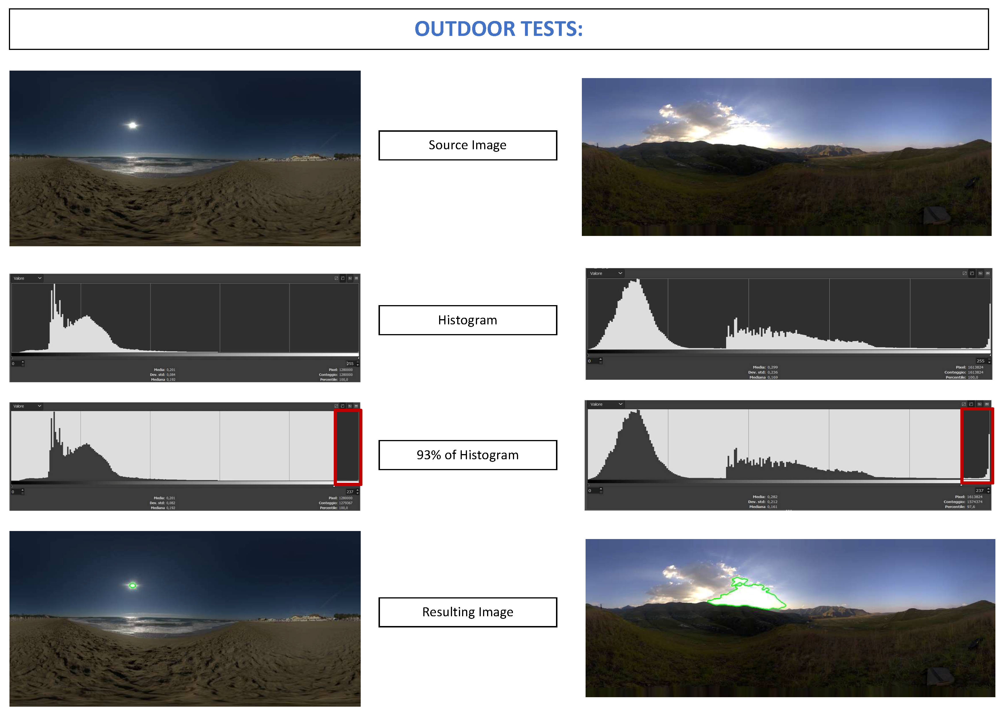
The parameters used were tested on several cases. Indoor and Outdoor environments were used to validate the method. Figure 11 shows the perfect matching between spotlight in indoor environment and the contour founded in processed image, while Figure 12 shows the same behavior of the code applied to outdoor environment, giving to ARPAS strong flexibility between different situations. It is important to notice that HoloLens Mixed Reality gives advantage in indoor environment due to the technology applied. Nevertheless, an extended application for future works is implemented here.
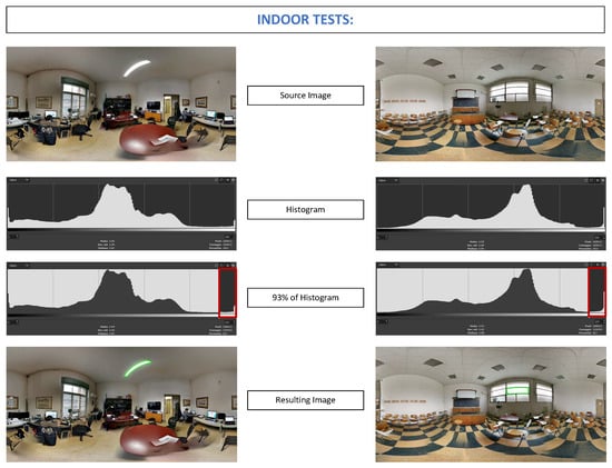
Figure 11.
ARPAS on indoor environment.
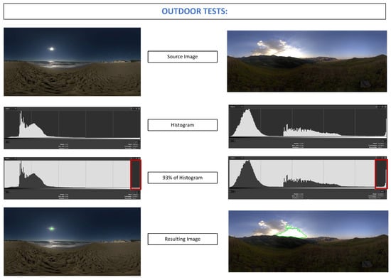
Figure 12.
ARPAS on outdoor environment.
3.5. Light Positioning in Unity Scene
The OpenCV image reference system is in the upper left corner, while the reference system of the Skybox HDR, inside the Unity scene, is in the center of the image. For this reason, a reference system change was made from OpenCV (O(x,y)) to Unity Skybox ().
For this purpose, a vector subtraction is required. It is important to notice that the y-axis is inverted, thus the new coordinates compared to the new origin are:
Once this is done, the point is univocally defined with respect to . The coordinate is proportional to a rotation around Unity y-axis, while is proportional to a rotation around Unity x-axis. Now, the relations between lengths and angles are:
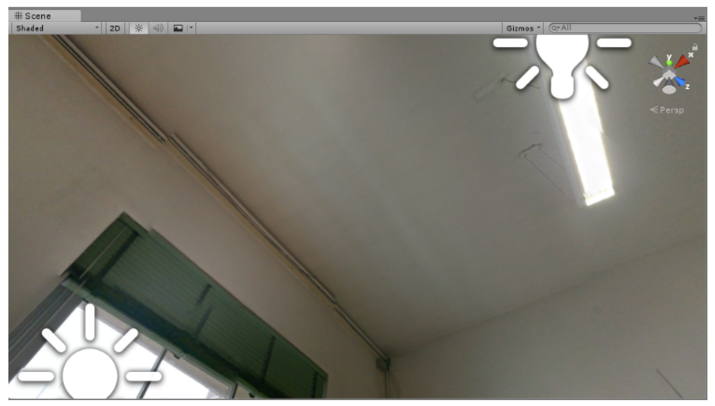
The image width corresponds to a 360 degree rotation around Unity y-axis, while the image height corresponds to 180 degree around Unity x-axis. The application of this algorithm to a real environment in Unity Editor gives effective results. Figure 13 shows that virtual lights are positioned precisely where real light sources are located, both natural light provided in this example from the sun through the window and artificial light from the chandelier. Thanks to a proper User Interface (UI), the user can select the self-positioned lights and define them as directional lights, spotlights or point lights. The user can now select a light source identified and posed by the algorithm and he can set the light source as directional, point light or spotlight (Figure 14). The distance from the HoloLensCamera, hence the user distance from the real light, is set manually by the user after selecting point lights and spotlights, and only for these two types of lights.

Figure 13.
Automatic light positioning in Unity editor.

Figure 14.
Light options UI.
4. Shadow Drawing
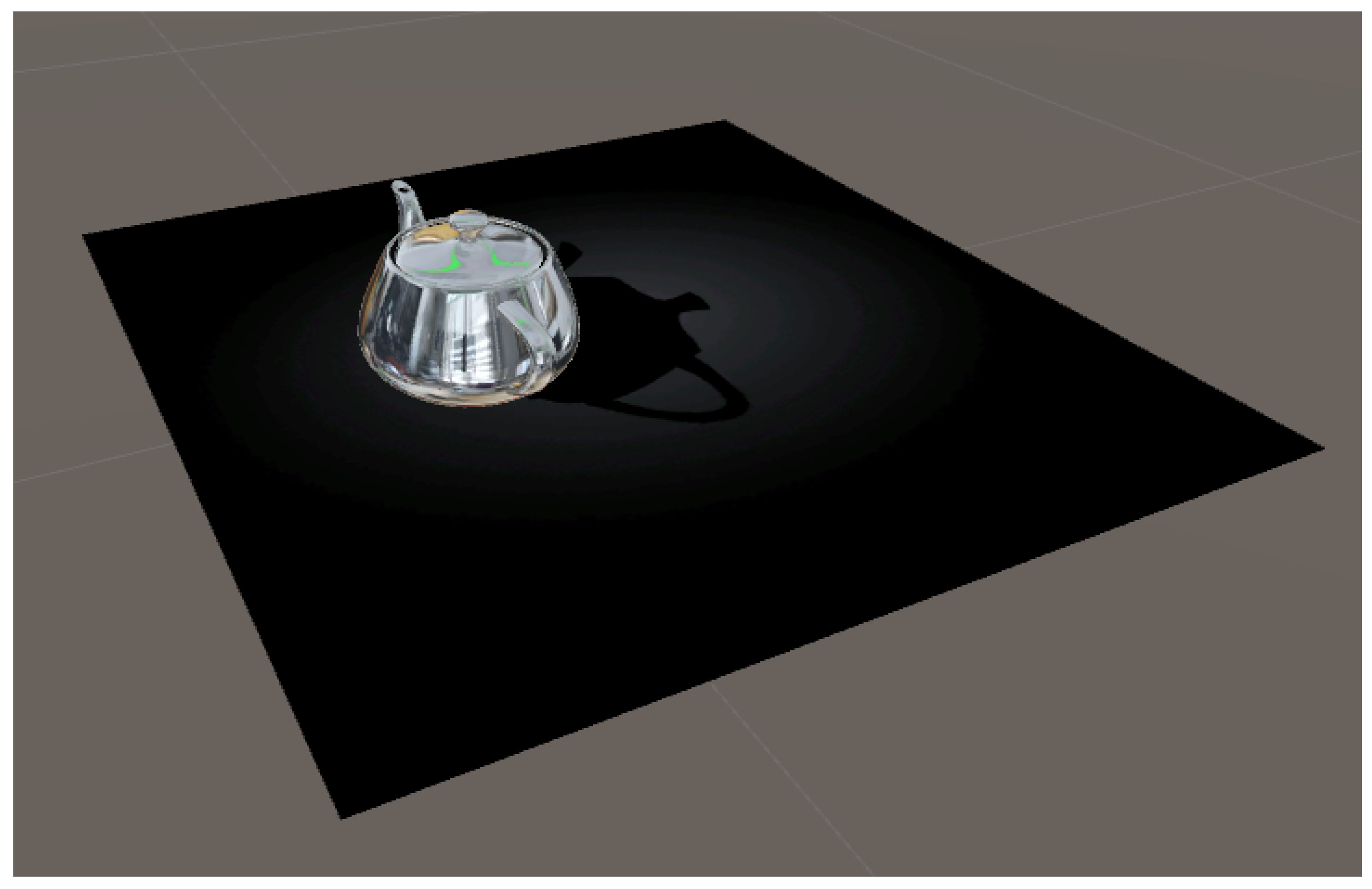
A separated treatment must be done on the representation of the shadows obtained with the method previously described. It is worth noting that, using HoloLens, the visualization of objects shadows is far from immediate and simple. In fact, the alpha channel in the lights combiners, the technology behind HoloLens, is the black color. In this way, the darker and more marked is a shadow is dark, the less it will be visible to the user, until the paradox whereby a shadow, or an object, completely black, will be invisible to the observer. This is also deducible from the fact that a completely black Skybox is set in the Unity editor to use HoloLens: thus, the device projects only the objects on the scene, deleting the background because it is black and therefore transparent [13]. Thus, the black color cannot be used with HoloLens. At this point, the difficulty of visualizing the shadow of an object is evident, since shadows are black. Here, the idea of a negative Shadow Drawing (SD) shader and ad hoc shader was created with the use of CG programming language (Figure 15).
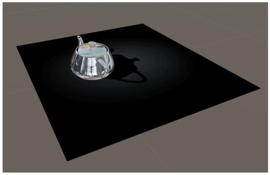
Figure 15.
Negative shadow effect.
The idea is to place a plane under each object with the material of the custom shader created, which allows the visualization of the shadow through an optic effect that we call “negative”. In fact, the background around the object is slightly lit, while the shadow of the object pierces this light. At this point, the optical effect is generated so that the black within the shadow of the object, which in reality is nothing but the true color of what we are looking at, seems to be darker than the black color on the external area. The effect is similar to a light pointing at the object. In such way, it is possible to display the shadows also without the black color.
Therefore, we can divide the problem into two parts: the SD shader and the object (called “floor object”) above which we apply the material with the custom shader.
4.1. SD Shader
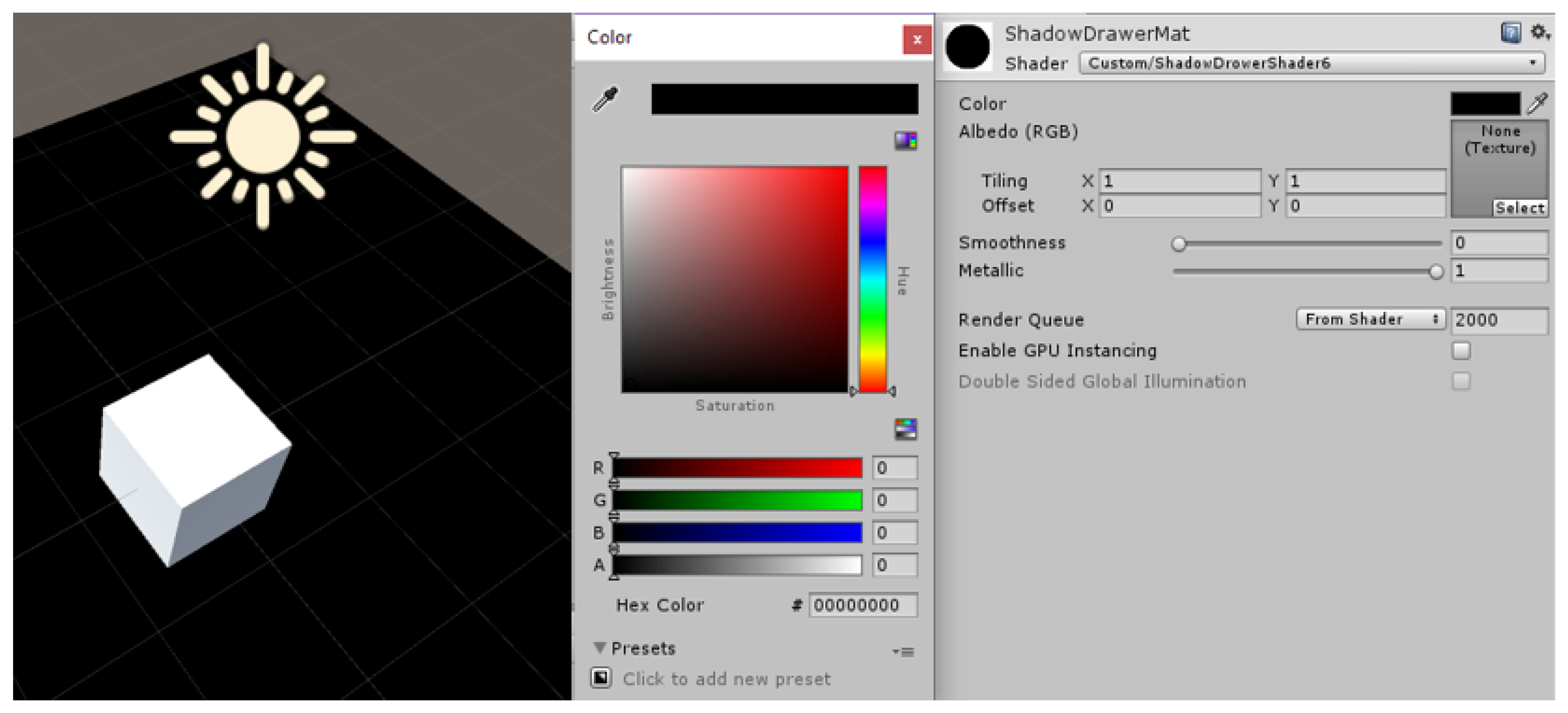
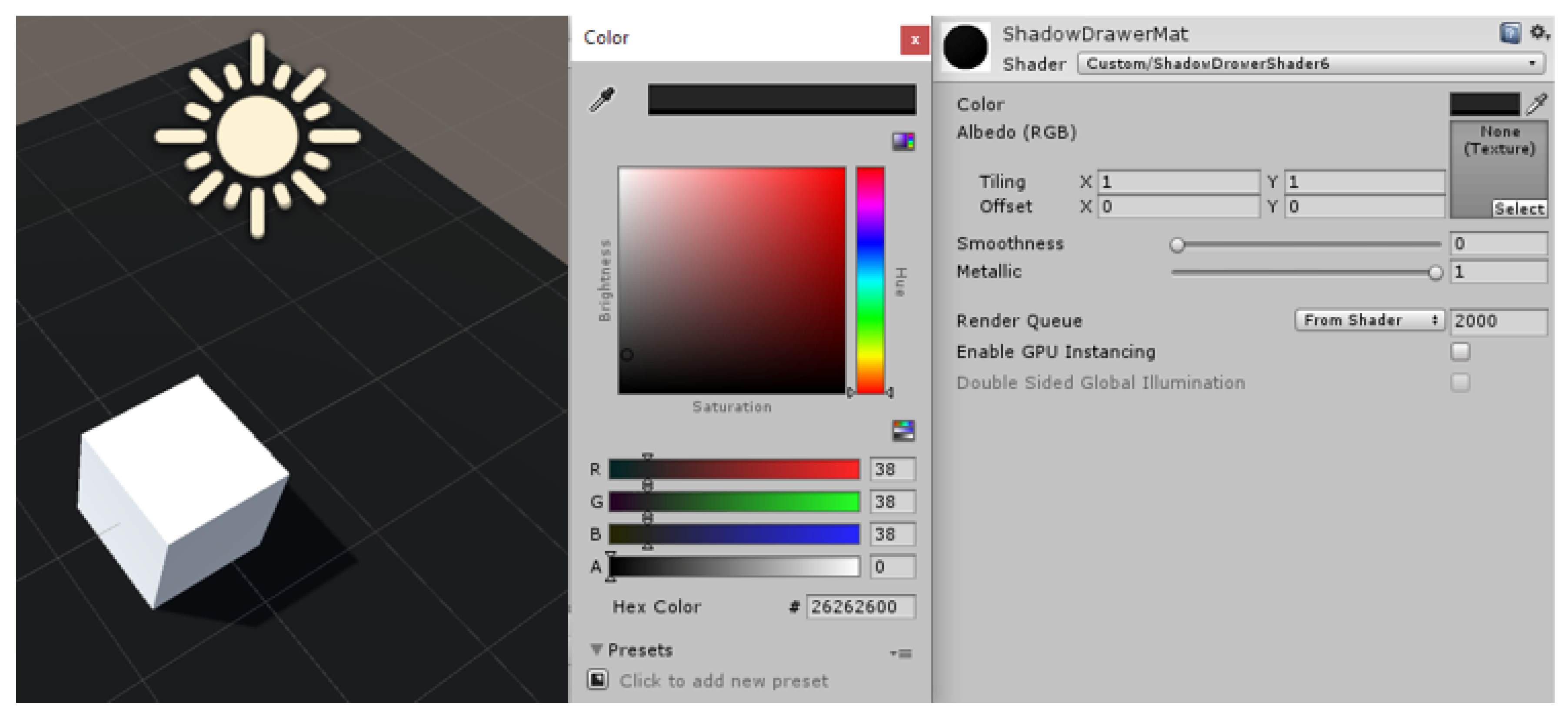
The CG script creates an artificial texture with specific color and properties. This 2D texture is then applied to the object that will be used as shadow catcher under the virtual model. If the color of the plane texture is set to black (Figure 16), the shadow disappears in the black plane underneath and in the HoloLens app nothing will appear. Instead, setting up a slightly grey (Figure 17) color for the texture, the “floor object” will be lighter while the shadow will remain black. This way we achieved the first step necessary to represent the negative shadow.
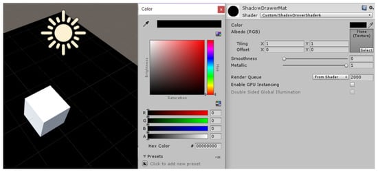
Figure 16.
SD with texture color set to “Black”.
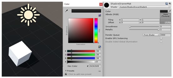
Figure 17.
SD with texture color set to “Grey”.
4.2. Floor Object
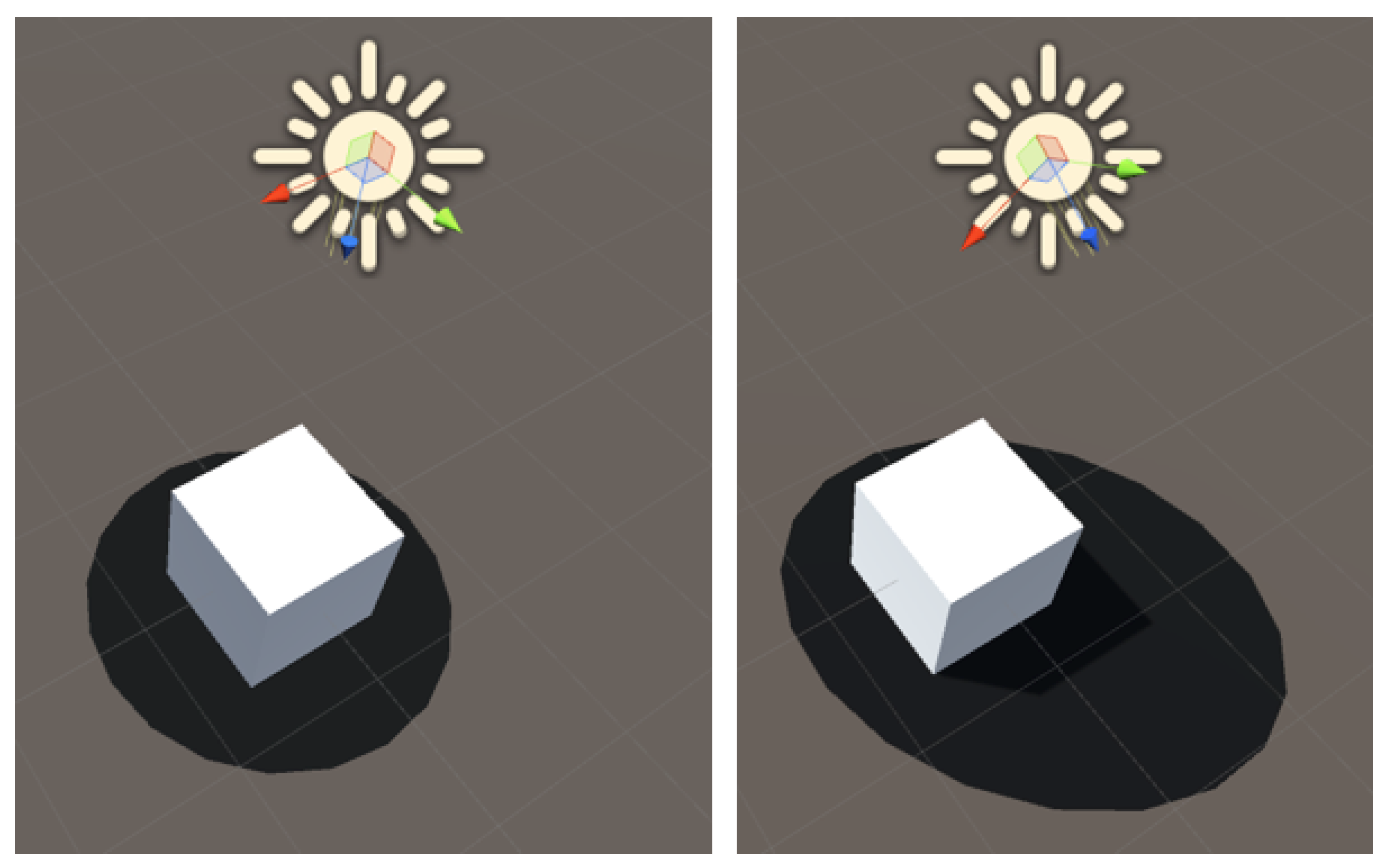
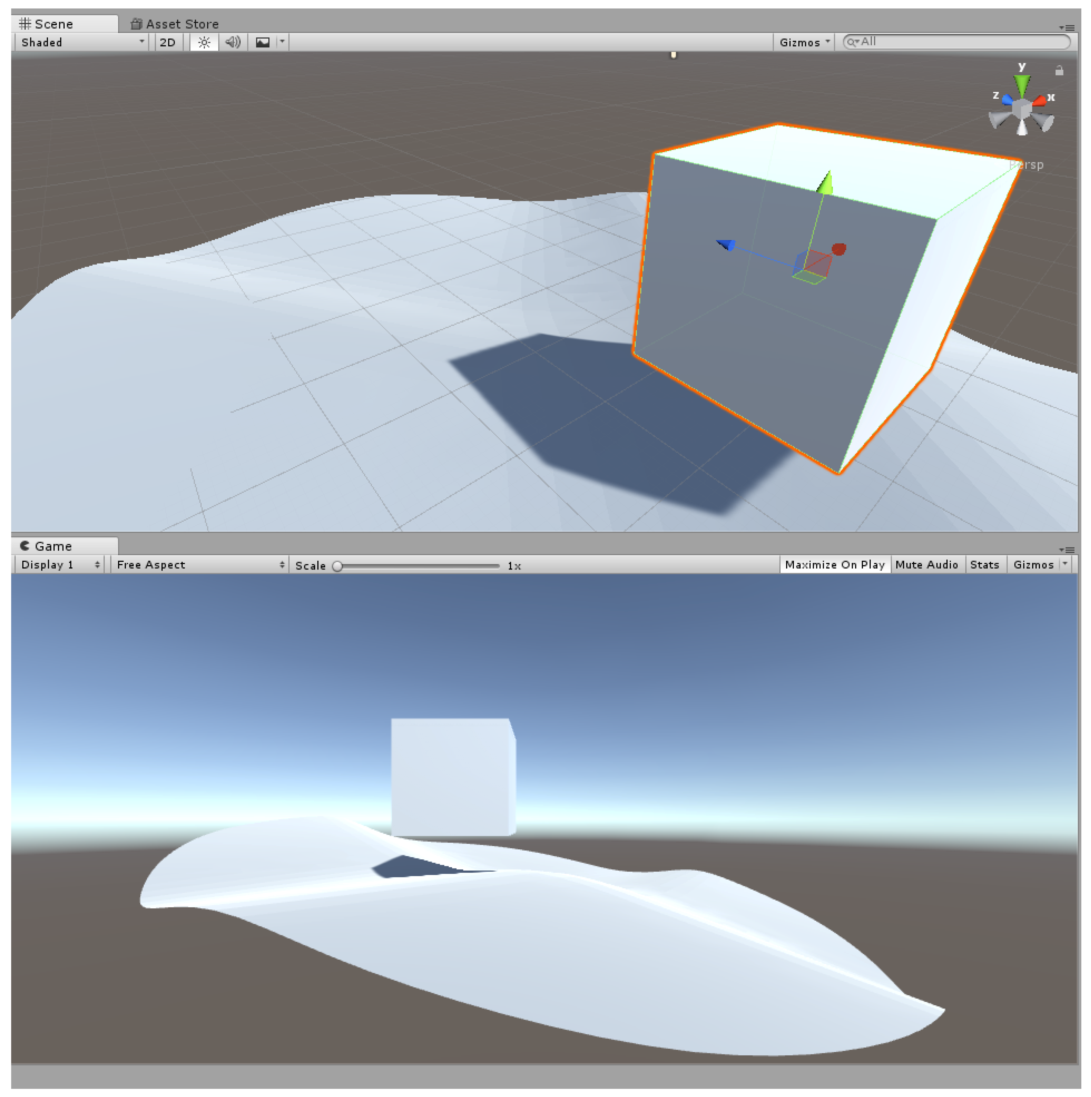
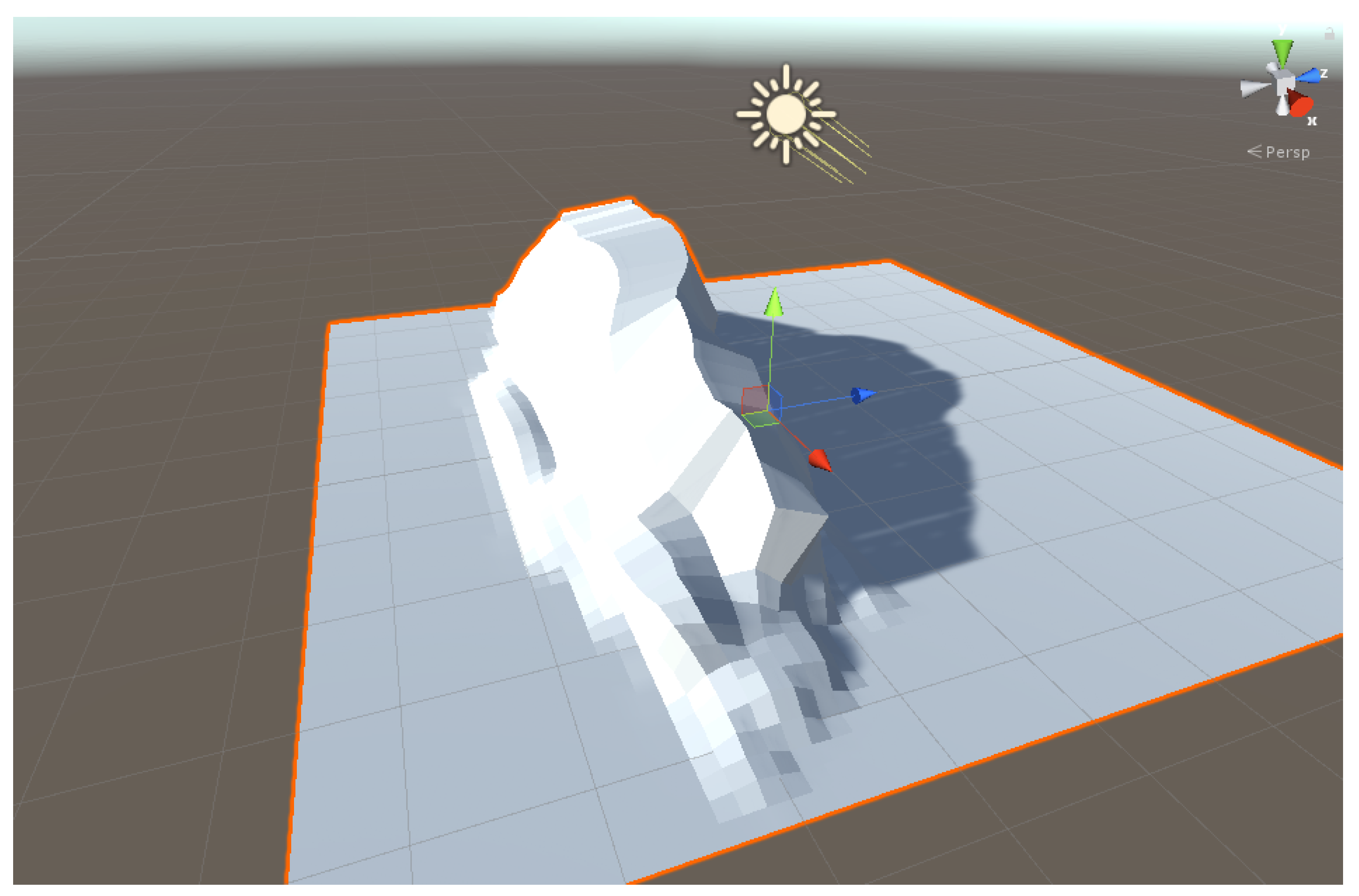
The second step is the “floor object” itself. To limit the area and reduce the computing resources, we applied our custom material to a “live” 2D object that evolved in real time with the orientation of the light. This “floor object” was set as a circle slightly larger than the virtual model and the calibration was performed pointing the light perpendicular to the floor. The rotation of the light and the elongation of the “floor object” were then linked so longer shadows could be caught without wasting space (Figure 18). In particular, the orientation and elongation were derived from the polar coordinates of the light with respect to the HDR origin and to the “floor object”. Non-planar shapes for the “floor objects” can be used, because the shadow projection relies on Unity rendering engine, as already mentioned in the Introduction (Figure 19). This is important because Unity engine is able to represent also self-shadows, allowing more complex shapes than a cube (Figure 20).
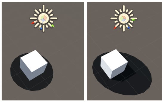
Figure 18.
“Floor Object” deformation.
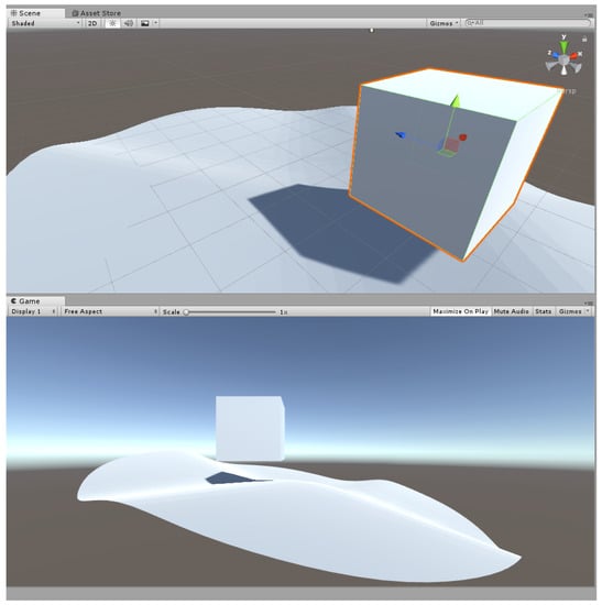
Figure 19.
Non-planar “Floor Object”.
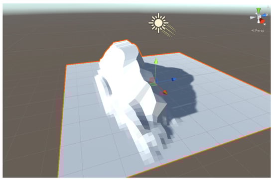
Figure 20.
Self-shadow representation with Unity engine.
5. Results
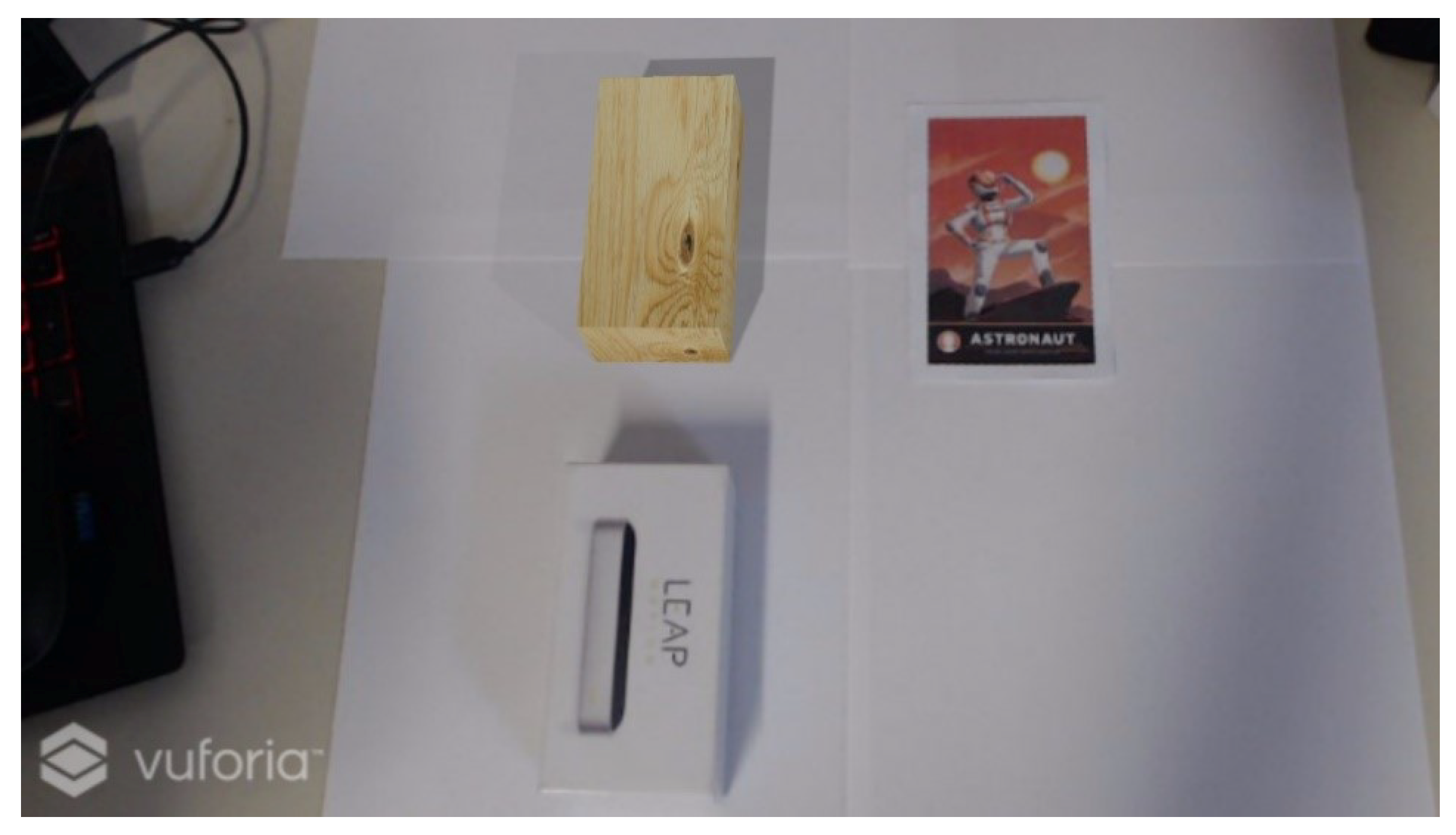
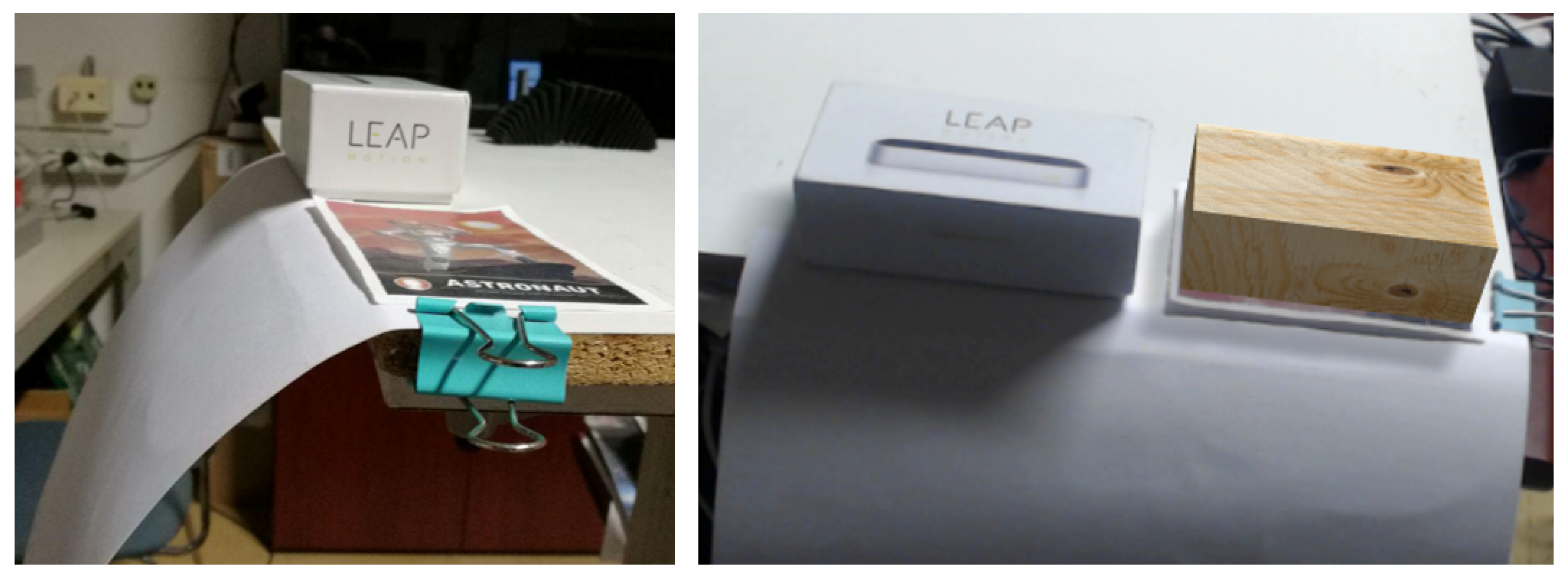
The integration of OpenCV and Unity achieved the first result: the perfect match between real shadows and virtual shadows (Figure 21 and Figure 22). The wooden box is the augmented object, while the Leap Motion box is the real object.
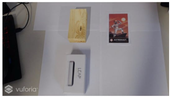
Figure 21.
Comparison between Real and Virtual Shadows.
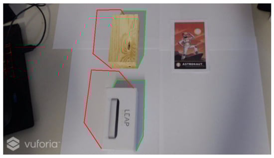
Figure 22.
Highlighting of shadow direction and shape.
There are two shadows because the procedure was reiterated several times allowing to find more than one light source. Inside the algorithm, it is possible to increase the iteration step allowing ARPAS to also identify minor light areas. This is important in indoor environment when both sunlight and artificial light are present. Figure 23 shows that the applied method correctly found both artificial light and sunlight, providing the right position of the source lights in Unity environment.
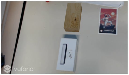
Figure 23.
Comparison between Real and Not Shadowed Object.
As shown in Figure 2, the algorithm discovered as light sources the lamp and the window, which was softer compared to the first one. The application can detect up to three light sources. The determination of light intensity is semi-manual based on Table 1 due to the simplicity of the implementation and because the light intensity overcame the original purpose of this study. The second result is the implementation of ARPAS in HoloLens. This step was achieved using the SD shader. Figure 24 shows that the negative shadow visual effect gives the expected result, also with more complex geometries (Figure 25 and Figure 26).

Table 1.
Light intensity.
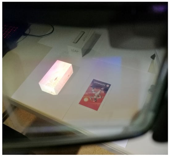
Figure 24.
HoloLens shadow representation.
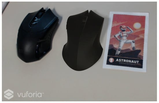
Figure 25.
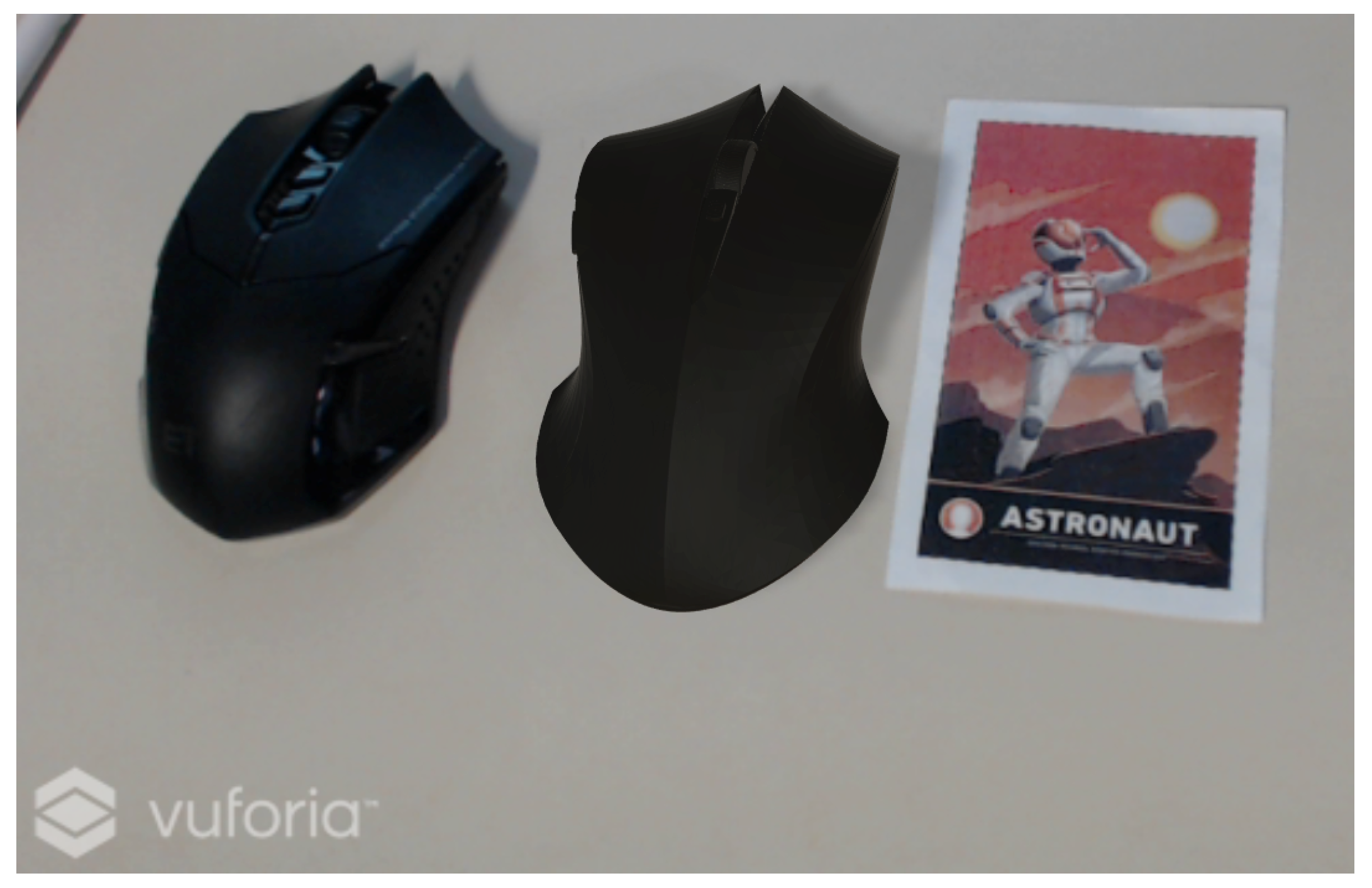
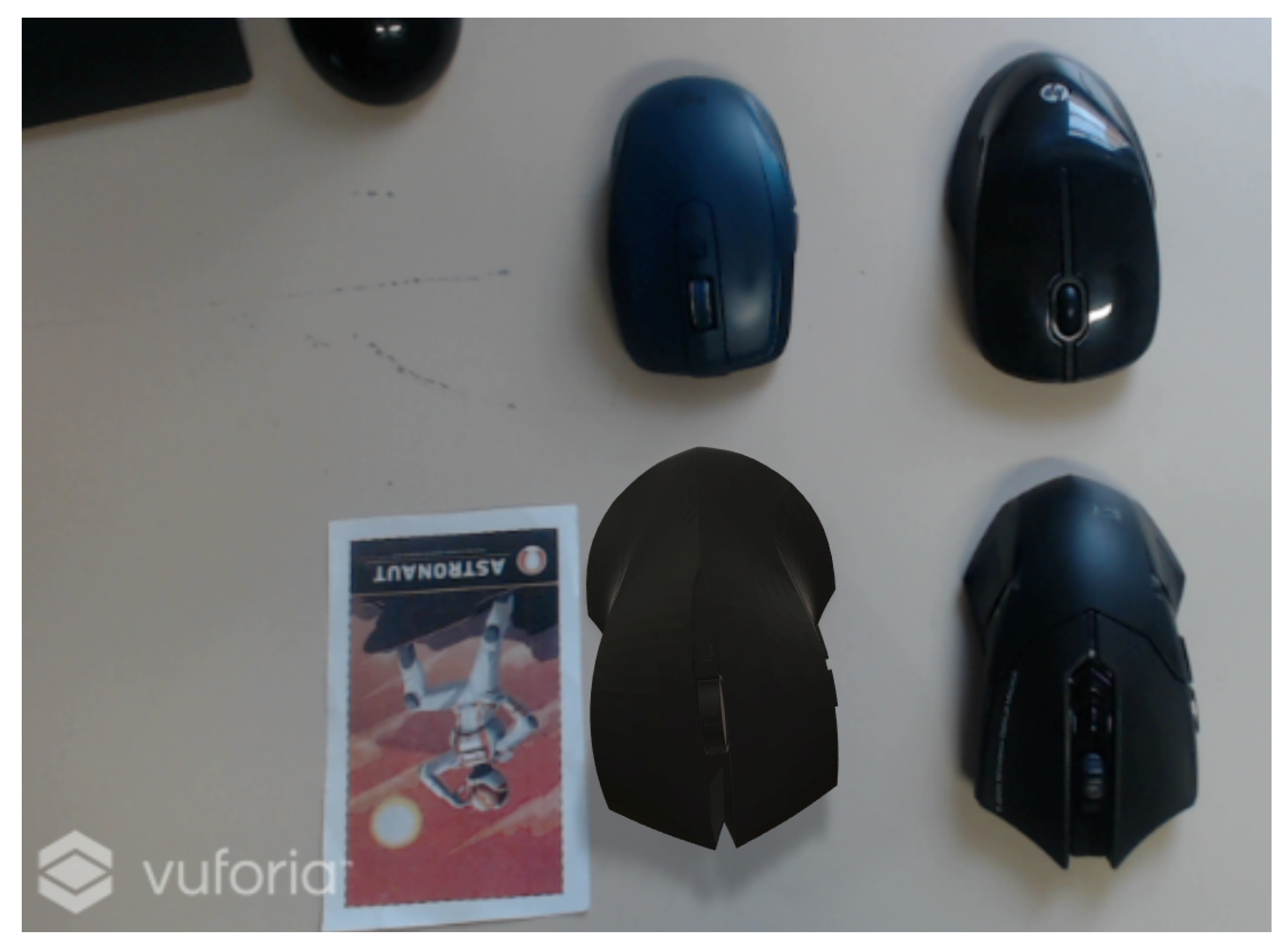
HoloLens shadow representation of a mouse (on the right).
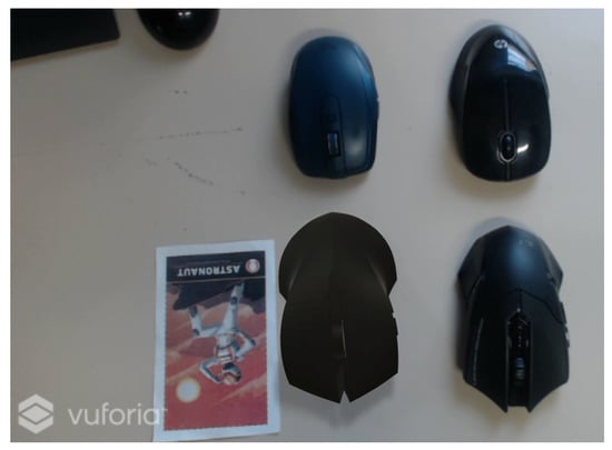
Figure 26.
Virtual mouse on bottom left side compared with real ones.
The limit of this application is the color matching between real and virtual shadows. The real shadow is darker than the environment, while the virtual shadow is the same color as the real environment. The brightening of the plane surrounding the wooden box shadow permits achieving the realistic shadowing.
6. Shortcomings
The method presents few shortcomings: the first one is related to the alpha channel in OST HMDs, such as HoloLens; the second one is related to the arbitrary choice of listing the detected light sources; and the third one refers to the projection of shadows under non-planar surfaces. Regarding the alpha channel, a meticulous calibration of the RGB values of the plane into which SD draws the shadow is required. These RGB values should be as near as possible to RGB = (0,0,0), because in the real world shadow is black, and, at the same time, they should be slightly higher than RGB = (0,0,0), for example RGB = (10,10,10), to create the illusion of negative shadow. If the chosen value were too high, the illusion would fade away because the plane with the SD shader would appear glowing and translucent. This is why underneath plane should be as white as possible; however, our SD works even with grey surfaces such as in Figure 25 and Figure 26. Regarding the listing of light sources by importance, as declared in Table 1, the intensity was set arbitrarily. This step should be ameliorated and improved, but the main focus of the work was to identify the light source into and HDR and to pose real-time virtual light source in the scene, such as directional lights and point lights. Area lights need to be baked into Unity; hence, they cannot be suitable for real-time applications. The second objective of the work was to enable the visualization of shadows onto a OST HMD. The problem of projecting shadows onto non-planar surfaces occurs because of the floor object. The floor object is defined planar (Figure 27 and Figure 28). The shadow on real surface appears as a projection of the shadow caught by the floor object through its normal direction. The distortion cannot be produced.

Figure 27.
Comparison between real and virtual shadows on a non-planar surface.
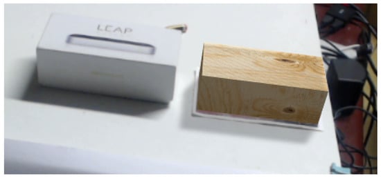
Figure 28.
Example of planar shadow projection.
7. Conclusions and Future Works
It is possible to make realistic shadow representation both on webcam (using Vuforia) and on HoloLens (using SD). In webcam applications, there is a complete match between the two results while, in HoloLens application, the shape of the shadow is the same, the technology is different, but the desired result is reached.
Although the negative shadow has been previously proposed to render holograms more realistic in a real environment, the real-time updating of the floor object shape with the negative shadow material, according to the polar coordinates of the lights sources, allows the HoloLens application to manage slight changes to the ambient light scheme. This allows fast changes to be made at the moment, for example: fast and small adjustments of the virtual lights with respect to their previous position in the real environment at the moment of the HDR spherical map creation. For more significant changes, on the other hand, which involve the complete change of the shadow map, the creation of the HDR spherical map is necessary but, in any case, not burdensome from the point of view of the time taken since it consists in reloading the initial pre-set scene. No Unity set-up is required when changes occur in the light environment scheme, and this makes the method fully portable and suitable for applications where, due to lack of time or laptop, it is not possible to edit the scene in Unity. For example, without our .dll, if changes were to occur, it would be necessary to create a new HDR spherical map with a 360 degree camera, import the image into Unity and set it as sky material, and build and deploy the app into HoloLens. This procedure should be repeated whenever a new light is placed in the real environment. Our .dll allows introducing new lights in the virtual environment without the use of the game engine, saving time and representing a less cumbersome procedure: simply take a 360 degree photo in the pre-set scene. This feature is very useful when the HoloLens user is not familiar with game engine software. Moreover, while the introduction of new light sources can be performed in a relatively short time with a moderate knowledge of game engine software, the negative shadows creation can be achieved in two different ways: a cutting mask or a glow effect underneath the object. However, the use of a cutting mask requires a preliminary step with a different software, and, obviously, the cutting mask is object shape dependent, hence not suitable for real-time changes. Similarly, the glow dimension underneath the object depends on the object itself dimensions, hence it requires editing the scene in Unity whenever lights intensity is modified or the object is changed. Both the methods above described require a higher level of knowledge of both game engine and third party software. Our contribution in the negative shadow technique consists in the fact that the application is end user ready and can be update in real time, based on the real time changes of the user surrounding environment.
For the future, there are some points that need to be optimized. First, it is important to couple a 360 degree camera with Microsoft HoloLens to speed up the initial pre-set scene. Today, the 360 degree photo is reached taking several photos and assembling them into a spheremap. The integration of a 360 degree camera will overcome this wasting of time returning immediately the desired image ready to be processed. A second issue is the automation of the shadows intensity computation and the correct soft-shadow [14] representation not to be confused with the blurred shadows of Unity. In this paper, the intensity settings are semi-manual because the shadow strength is proportional to the pixel area, i.e., the pre-set threshold value, caught by OpenCV. Actually, this is not enough because it depends on the type of real light (artificial light or natural light) and consequently by choosing the correct virtual light (directional, spot, point, area).
As for the tests in different lighting scenarios, our study focused mainly on indoor directional lights. On the one hand, we studied only indoor environment since HoloLens technology relies on additive displays so virtual contents are created by adding light to the light from the real world. This means that in outdoor environments the hologram’s visibility is compromised by the sunlight, so the negative shadow effect is scarcely visible. On the other hand, other types of lights, such as area lights and point lights, do not support real time shadows rendering in Unity previous release, hence these lights were not suitable for real time applications. Different lighting scenarios, including point lights and spotlights, which now support real time rendering, have been included in this research via a lighting options UI menu. However, it is worth noting that the implementation of point lights and spotlights need to be coupled with the integration of HoloLens Spatial Mapping data since the integration of the spheremap and OpenCV with HoloLens Spatial Mapping could solve the problem giving the exact shape and distances of the environment, allowing to anchor light in the right position. Previously, every light was a directional light for two reasons: they were the only ones with real time shadows rendering and the z-coordinate was set a priori because it did not influence the shadow shape onto the floor object, since, with directional lights, the light comes from infinite distance. If we had chosen a different light, the position on z-axis would have been relevant, for example in the definition of the spotlight’s cone angle and range, and this information would not have been derivable simply analyzing the 360 degree photo with OpenCV. However, now that spotlights and point lights support real time rendering, we added a UI menu allowing the user to choose from directional lights, spotlights and point lights. The distance from the user is set manually, and next step of the research is to pose spotlights and point lights according to HoloLens Spatial Mapping data. A separate discourse needs to be done for area lights. These lights still only support baked shadows, hence it is not yet possible to include them in real time applications, and this shortcoming is independent from our method. Finally, the possible integration of HoloLens Spatial Mapping data should be considered to overcome the problem of non-planar shadow projection. Extracting environment data from HoloLens range camera near the virtual object could ameliorate the resulting visual effect of shadows onto non-planar real surfaces. However, the use of SD Shader as material of the entire spatial mapping mesh is not a viable solution since the user would see a glow effect over the whole real scene, compromising the perceived realism. In addition, Spatial Mapping data could slow down the application and the computational effort for HoloLens could be excessive in a standalone application, hence this next step is currently under study.
Author Contributions
Conceptualization, F.O. and G.M.S.; methodology, G.C.; software, G.M.S.; validation, F.O. and G.M.S.; supervision, G.C.; project administration, G.C.; funding acquisition, G.C.
Funding
This research received no external funding.
Conflicts of Interest
The authors declare no conflict of interest.
References
- Liverani, A.; Ceruti, A.; Caligiana, G. Tablet-based 3D sketching and curve reverse modelling. Int. J. Comput. Aided Eng. Technol. 2013, 5, 188–215. [Google Scholar] [CrossRef]
- Yu, L.; Li, W.K.; Ong, S.K.; Nee, A.Y.C. Enhanced Planar Pattern Tracking for an Outdoor Augmented Reality System. Int. J. Comput. Electr. Autom. Control. Inf. Eng. 2017, 11, 156–167. [Google Scholar]
- Ufkes, A.; Fiala, M. A Markerless Augmented Reality System for Mobile Devices. In Proceedings of the 2013 International Conference on Computer and Robot Vision, Regina, SK, Canada, 28–31 May 2013; pp. 226–233. [Google Scholar] [CrossRef]
- Bajana, J.; Francia, D.; Liverani, A.; Krajčovič, M. Mobile Tracking System and Optical Tracking Integration for Mobile Mixed Reality. Int. J. Comput. Appl. Technol. 2016, 53, 13–22. [Google Scholar] [CrossRef]
- De Amicis, R.; Ceruti, A.; Francia, D.; Frizziero, L.; Simões, B. Augmented Reality for virtual user manual. Int. J. Interact. Des. Manuf. (IJIDeM) 2018, 12, 689–697. [Google Scholar] [CrossRef]
- Ceruti, A.; Liverani, A.; Bombardi, T. Augmented vision and interactive monitoring in 3D printing process. Int. J. Interact. Des. Manuf. (IJIDeM) 2017, 11, 385–395. [Google Scholar] [CrossRef]
- Debevec, P. Rendering Synthetic Objects into Real Scenes: Bridging Traditional and Image-based Graphics with Global Illumination and High Dynamic Range Photography. In Proceedings of the 25th Annual Conference on Computer Graphics and Interactive Techniques, SIGGRAPH ’98, Orlando, FL, USA, 19–24 July 1998; ACM: New York, NY, USA, 1998; pp. 189–198. [Google Scholar] [CrossRef]
- Aittala, M. Inverse lighting and photorealistic rendering for augmented reality. Vis. Comput. 2010, 26, 669–678. [Google Scholar] [CrossRef]
- Jachnik, J.; Newcombe, R.A.; Davison, A.J. Real-time surface light-field capture for augmentation of planar specular surfaces. In Proceedings of the 2012 IEEE International Symposium on Mixed and Augmented Reality (ISMAR), Atlanta, GA, USA, 5–8 November 2012; pp. 91–97. [Google Scholar]
- Rohmer, K.; Buschel, W.; Dachselt, R.; Grosch, T. Interactive near-field illumination for photorealistic augmented reality on mobile devices. In Proceedings of the 2014 IEEE International Symposium on Mixed and Augmented Reality (ISMAR), Munich, Germany, 10–12 September 2014; pp. 29–38. [Google Scholar] [CrossRef]
- Kolivand, H.; Noh, Z.; Sunar, M.S. A quadratic spline approximation using detail multi-layer for soft shadow generation in augmented reality. Multimed. Tools Appl. 2013, 73, 1225–1245. [Google Scholar] [CrossRef]
- Gruber, L.; Langlotz, T.; Sen, P.; Hoherer, T.; Schmalstieg, D. Efficient and robust radiance transfer for probeless photorealistic augmented reality. In Proceedings of the 2014 IEEE Virtual Reality (VR), Minneapolis, MN, USA, 29 March–2 April 2014; pp. 15–20. [Google Scholar] [CrossRef]
- Saarikko, P.; Kostamo, P. Waveguide. US Patent 2016/0231568 A1, 11 August 2016. [Google Scholar]
- Fernando, R. Percentage-closer Soft Shadows. In Proceedings of the ACM SIGGRAPH 2005 Sketches, SIGGRAPH ’05, Los Angeles, CA, USA, 31 July–4 August 2005; ACM: New York, NY, USA, 2005. [Google Scholar] [CrossRef]


© 2019 by the authors. Licensee MDPI, Basel, Switzerland. This article is an open access article distributed under the terms and conditions of the Creative Commons Attribution (CC BY) license (http://creativecommons.org/licenses/by/4.0/).