Article

Aerodynamic Performance of Quadrotor UAV with Non-Planar Rotors

1
School of Mechanical Engineering and Automation, Fuzhou University, Fuzhou 350116, China
2
Key Laboratory of Fluid Power and Intelligent Electro-Hydraulic Control (Fuzhou University), Fujian Province University, Fuzhou 350116, China
*
Author to whom correspondence should be addressed.
Appl. Sci. 2019, 9(14), 2779; https://doi.org/10.3390/app9142779
Submission received: 4 June 2019 / Revised: 6 July 2019 / Accepted: 8 July 2019 / Published: 10 July 2019
(This article belongs to the Special Issue Autonomous Micro Aerial Vehicles: Methods and Applications)

Abstract

:
The mobility of a quadrotor UAV is significantly affected by its aerodynamics, especially when the closely spaced rotors are applied in the multi-rotor system. This paper addresses the aerodynamic modeling of non-planar quadrotor UAV with various rotor spacing (1 d–2 d) and disk plane angle (0–50 deg). The inter-rotor interference and the power models are also proposed in this paper. In order to validate the non-planar model, a series of CFD analyses and experiments were conducted. The obtained results demonstrate that the flow field of the non-planar quadrotor is extremely complicated when the unsteady flow is involved. The pulsation of partial angle of attack and pressure distribution is formed when the blade passes through the vortex. The thrust is increasing significantly along with the tilt angle, resulting from the stronger outflow of the non-planar rotors, which is also leading the power increment. However, the thrust increment is not that obvious when the spacing is larger than 1.4 d. The experiments and the numerical simulation results provide consistent trends and demonstrate the effectiveness of the aerodynamic model of the non-planar quadrotor. The comparison with the traditional planar quadrotor validates that the proposed non-planar quadrotor has better aerodynamic and control performances with a larger power loading.

1. Introduction

The quadrotor has a wide range of applications in both military and civilian applications due to its ability to adapt to all types of flight conditions. For a traditional planar quadrotor UAV, rotors are rotating in the same plane with four degrees of freedom. When rotors are tilting an angle around the axis of the rotor arm, this kind of non-planar quadrotor UAV obtains the six degrees of freedom. Additionally, the rotation speeds of four rotors are the only four independent control inputs, which do not allow independent control of the position and attitude. For example, the horizontal movement needs the change in the attitude [1,2,3,4,5,6,7,8]. Therefore, inspired by the tilt angle of the rotor, a non-planar quadrotor structure with a more controlled advantage has been developed in last 5 years [2]. The non-planar quadrotor has an additional actuation freedom that provides complete control of the position and the orientation of the quadrotor, making it virtually a fully actuated aircraft. Considering that the non-planar design provides a total of 6 degrees of freedom of manoeuvrability, the manoeuvrability will be an important feature of many future applications of UAVs, especially those involving interaction/manipulation in a complex environment.
However, most of the research conducted for quadrotor has focused on attitude control and trajectory tracking. Salih and Li, et al., used a PID controller-stabilized quadrotor in simulation and actual flight experiments [9,10,11]. Also, in [12,13], the reverse thrust and sliding mode methods have been utilized to control the quadrotor tracking trajectory. Markus and Efraim, et al., established the dynamic model of additional aerodynamic effects for non-planar quadrotor aircraft and proposed a non-linear trajectory tracking controller based on dynamic feedback linearization technology [2,6]. The literature shows that the aerodynamic model of quadrotor has been oversimplified in most studies. Therefore, the accuracy of the aerodynamic model needs to be improved [14]. Turpin, et al., observed that the error of the quadrotor model increased the error of the desired trajectory [15]. The STARMAC project team from Stanford University applied the blade flapping and thrust changes to model at high-speed forward flight [16]. The control effect has been significantly improved but the aerodynamic model is still simplified.
Currently, only few studies have been conducted on the distribution of the flow field for quadrotor. Yasuda proposed a coupled flow simulation method, which is leading a fundamental understanding of the flight behavior of the quadrotor [17]. Luo, et al., proposed a mathematical model at forward flight considering the interference of the rotor in hovering [18]. Powers discussed the modeling of the quadrotor under different flight conditions, including lower wind speeds considering the ground effect [19]. Nguyen and DucHung studied the aerodynamic characteristics of a quadrotor helicopter in a uniform flow field through wind tunnel tests and the aerodynamic interference problem of the twin-rotor structure [20]. Derya derived the force and moment of the quadrotor using the blade element momentum theory [21]. Yeong studied the aerodynamic design of the propeller with the shear stress transport K-Omega (SST k-ω) turbulence model and optimized the aerodynamic performance of the UAV [22]. Je, et al., demonstrated that the aerodynamic interference is much more complex than the isolated single-rotor flow field, such as thrust fluctuations [23]. These preliminary results are advantageous to understand the flow field of the quadrotor. However, there is no research focusing on the flow field around the non-planar quadrotor and its aerodynamic characteristics. Besides, an oversimplified model is not suitable for describing the unique aerodynamic characteristics. Above all, it is necessary to study the aerodynamic characteristics of the non-planar rotors with different spacing and tilt angle.
The structure of this paper is organized as follows. In Section 2, the mechanism of mutual interference of non-planar quadrotor systems is studied. An aerodynamic model for the non-planar quadrotor, and the influence of the rotor spacing and tilt angle on the aerodynamic performance is described in details. In Section 3, CFD simulations are performed to study the flow field of the non-planar quadrotor with different spacing and tilt angle. In Section 4, the entire thrust and power are obtained by experiments. Finally, Section 5 provides the conclusions.

2. Aerodynamics of the Quadrotor

Considering there is a tilt angle of each rotor, the inflow and the downwash of the non-planar quadrotor are totally different from the traditional planar quadrotor. The flow field is more concentrated with stronger interference. Therefore, the aerodynamic characteristics of an isolated rotor under generalized motion are analyzed by momentum theory and blade element theory. Figure 1 shows the structure of non-planar quadrotor.
In the Figure 1, the tilt angle is the rotation angle around the support arm, and the spacing l is the distance between centers of adjacent rotor. For the non-planar rotors with different configuration, take 30-1.5 for example, it indicates that the rotor is rotated 30 deg around the support arm and the adjacent rotor center distance is 1.5 d (d is the rotor diameter).

2.1. Aerodynamics of the Isolated Rotor

The momentum theory of the isolated rotor is showed in the Figure 2.
The induced velocity and thrust under generalized motion is [18,24,25,26]:
v i = v h 2 ( V cos α ) 2 + ( V sin α + v i ) 2
T = 2 ρ A V v
v h 2 = T / 2 ρ A
where vh is the induced velocity at hover and V is the total velocity.
V = ( V cos α ) 2 + ( V sin α + v i ) 2
The geometry, the section direction of the blade element theory is showed in Figure 3 and Figure 4.
The dotted line in Figure 4 represents the zero-lift line. α and θ are the aerodynamic angle of attack and the installation angle of the blade profile, respectively. V is the relative velocity, and ϕ is the angle of the blade profile. Therefore, the thrust coefficient is [20,21]:
C T = 1 2 π 0 R 0 2 π Δ F T ρ A ( Ω R ) 2 d Ψ d r
T = C T ρ A ( Ω R ) 2
where Ψ is the azimuth of the rotor blade.
The rotor inflow ratio and the advance ratio under generalized motion are defined as:
μ = V cos α ω R
λ = V sin α + v i ω R = μ tan α + λ i
The V is the velocity from the far-field. Assume that the installation angle of the blade profile changes linearly:
θ = θ 0 + θ t w r
Then the isolated rotor thrust coefficient under generalized motion is given as:
C T σ α = ( 1 6 + 1 4 μ 2 ) θ 0 + ( 1 + μ 2 ) θ t w 8 1 4 λ
T = σ α { ( 1 6 + 1 4 μ 2 ) θ 0 + ( 1 + μ 2 ) θ t w 8 1 4 λ } ρ A ( Ω R ) 2
where σ is the rotor solidity.
As shown in Figure 4, the hub force is the resultant force acting on the propeller, which is the integral of the airfoil section. The blade element theory provides an expression of the hub force coefficient. The resistance can be divided into the induced resistance CHi and the profile resistance CH0. Thus, the hub coefficient is given as:
C H = C H 0 + C H i
According to the blade element theory, the induced resistance is expressed as:
C H i = 1 2 σ C l α ( θ 0 2 + θ t w 4 ) μ λ
and the profile resistance is given as:
C H 0 = σ C d 4 μ
According to the momentum theory, the power is expressed as:
P = T ( V sin α + v )
Under the assumption of uniform inflow of momentum theory, the power coefficient is:
C P = λ i C T + 1 8 σ C d ( 1 + μ 2 ) + μ C H

2.2. Aerodynamic Model of a Non-Planar Quadrotor Considering Rotor Interference

The multi-rotor system is defined as the non-linear superposition considering the wake disturbances. An interference model based on the overlap of the flow field is proposed, and the interference between the induced velocity vm is applied to describe the real interference between the rotors [27].
v m = v i m + n m χ m n v i n
λ m = λ i m + n m χ m n λ i n = μ m tan α + λ i m
Vin and Vim are the actual induced velocity of the isolated nth and mth rotors, respectively; χmn is the interference factor of the nth rotor to m rotor. If χmn is greater than 0, the interference of the nth-rotor decreased the performance of the mth-rotor, vice versa. For the non-planar quadrotor system studied in this paper, taking rotor 2 as an example (rotor 1, and rotor 3 are two adjacent rotors of rotor 2), the induced velocity and the inflow rate are expressed as:
v 2 = v 2 i + χ 32 v i 3 + χ 12 v i 1
λ 2 = λ i 2 + χ 32 λ i 3 + χ 12 λ i 1
The inflow variation is expressed as:
Δ λ i m = χ m λ i s o l a t e d = Δ v i m v i . i s o l a t e d
According to [18], the real thrust coefficient is expressed as:
C T m = ( 1 1 8 σ C l μ χ m ) C T . i s o l a t e d
Similarly, the hub force coefficient CHm of the mth rotor is given as:
Δ C H m = C H m C H i s o l a t e d
C H m = C H . i s o l a t e d + 1 4 σ C l ( θ 0 2 + θ t w 4 ) χ m C T . i s o l a t e d

2.3. Power Model of a Non-Planar Quadrotor

In this paper, power loading (PL) of the isolated rotor is defined as [28]:
P L = T q u a d r o t o r s P q u a d r o t o r s
A large PL implied a better performance with lower power consumption and higher thrust.
According to the blade element theory, the power of the non-planar quadrotor includes three coefficients: The resistance power coefficient, the effective power coefficient, and the induced power coefficient.
The resistance power coefficient is:
m K X = σ 0 R C d r 3 d r = σ 0 R K P C d r 3 d r = 1 4 K P σ C d
where KP is the correction factor considering the influence of the non-uniform distribution of the resistance on the power based on the blade geometry.
The effective power coefficient is:
m K y x = 0 R C l r 2 V 0 d r = C T V 0
where V0 is the slip velocity considering the adjacent rotor interference.
The induced power coefficient is:
m K i = σ 0 R C l r 2 v i d r = J C T v ¯ i
where J is a correction coefficient considering the induced velocity.
Conclusively, the required power of a non-planar quadrotor is expressed as:
m K = 1 4 K P σ C d + C T V 0 + J C T v i
Therefore, the slip velocity of the face-to-face rotors increases along with the tilt angle and decreases along with the rotor spacing. The induction velocity of the back-to-back rotors shows the similar trend. Additionally, for a same rotor profile, the power required by the quadrotor UAV may also increase at a smaller spacing or a larger tilt angle.

3. Computational-Fluid-Dynamics Analysis

Motions of the quadrotor depend on the variable speed of each rotor, which makes the aerodynamic performance design more challenging. It is also necessary to consider other factors such as the balance of the moment, and the stability of the crosswind. Moreover, the aerodynamic interference between the rotors is complex, and it is difficult to analyze the aerodynamic performance through flight test or wind tunnel test only. Therefore, the CFD simulation is our best choice to optimize the performance with a large number of combinations.
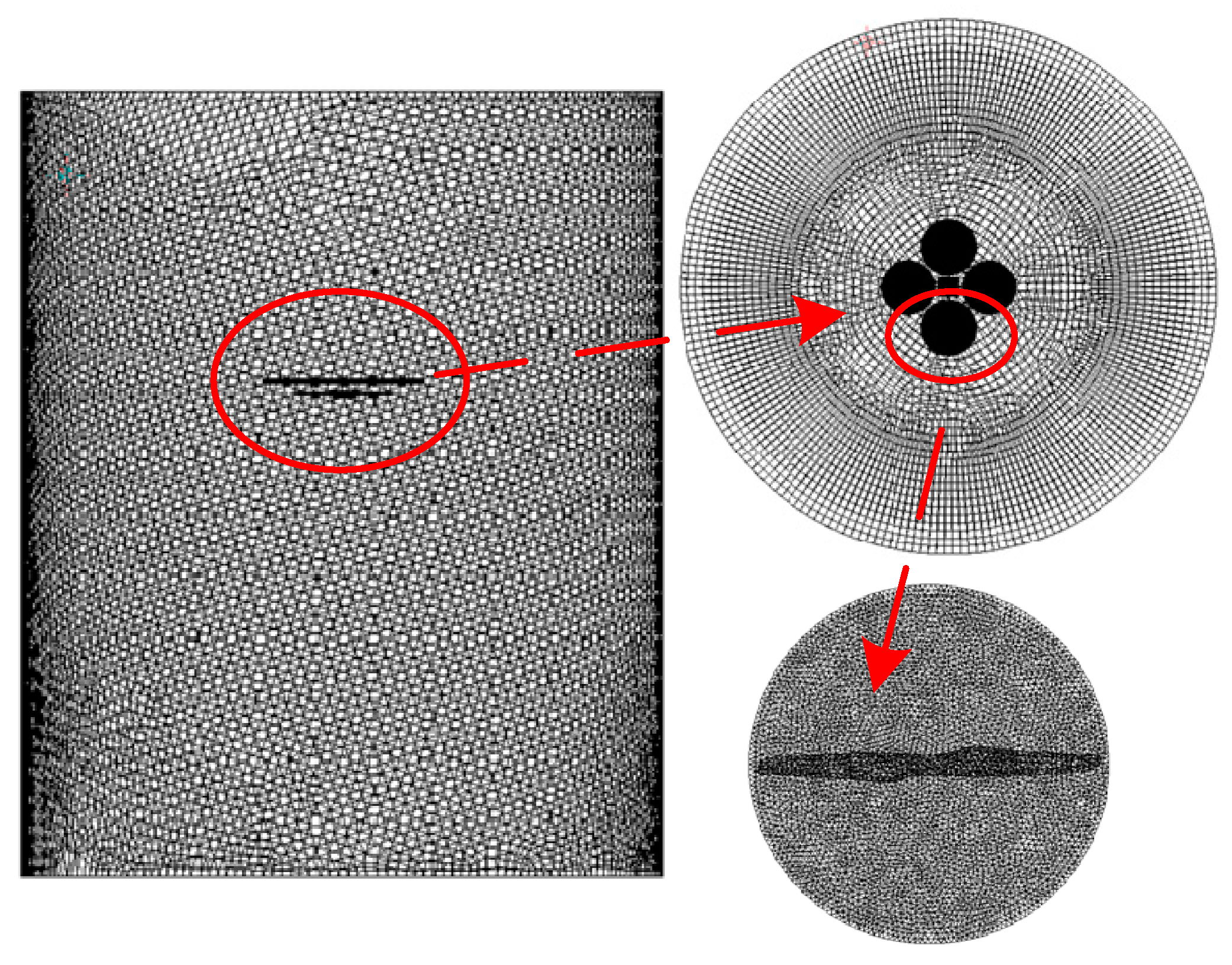
In order to study the mutual interaction between the rotors, various combinations with different spacing (1 d–2 d) and tilt angle (0–50 deg) are numerically simulated with ANSYS. The N-S equation model is applied to analyze the characteristics of the external flow field [29]. Also, mesh refinement is performed on four rotor regions with a large gradient of physical field flow. According to the airfoil geometry, the Reynolds number is approximately 1.1 × 10⁵, so the fluid is treated as incompressible. Additionally, the finite volume method is used to discrete the differential equations. Considering the low Reynolds number environment, the Spalart-Allmaras model is selected to obtain the flow field of the non-planar rotor pairs. The pressure correction is performed using the Semi-Implicit Method for Pressure Linked Equations (SIMPLE) algorithm, and the pressure interpolation is selected in the standard format. Momentum, energy equation, and turbulent viscosity are all in the first-order upwind discrete format for the initial simulation, then the second-order upwind is applied in the final simulations. The rotor speed is set at 2200 rpm. At last, the sliding grid is used to deal with the interaction between the rotating and the stationary regions, and then the steady state calculation result of the Multiple Reference Frame (MRF) method is applied as the initial condition for the slip mesh transient calculation. The mesh distribution is showed in Figure 5.

3.1. CFD Simulations for the Isolated Single Rotor

Figure 6 shows the thrust variation of the isolated rotor with azimuth angle at 2200 rpm.
The steady state calculation obtained by the MRF method is used as the initial value. It can be seen from Figure 7 that and the thrust value shows a stable periodicity after 1.5 turns of the isolated rotor. Therefore, the average thrust during the stabilization period is taken as the exact value of the rotor. The thrust value of the quadrotor is also taken from the average over the stable period.
Figure 7 shows the simulation results of the isolated rotor.
Figure 7a,b shows the radial and the axial flow diagrams of an isolated rotor. The streamline spiral through the paddles, and the downwash affected area exceeds three times the rotor diameter. It can be expected that the non-planar rotors will be dominated by the outflow. Therefore, the overlapping interference of the flow field may be more obvious when the spacing is small or the tilt angle is large. The following section will further analyze the specific impact of this interference and the specific distribution of overlapping flow fields. Figure 7c shows the distribution of the low vortex system in the isolated rotor simulation of the blade tip vortex. Figure 7d shows the vertical downward velocity (w) contour distribution of the isolated rotor. It can be seen that the unsteady downwash caused by the tip vortex is very strong. The two blades flow field of the undisturbed isolated rotor is symmetrically distributed in the center, while the non-planar rotors will be affected by the mutual interference.

3.2. Simulation Results of Non-Planar Quadrotor

Figure 8 shows the pressure and the velocity contours of the planar quadrotor on the vertical plane with rotor spacing of 1.05 d.
It can be seen that with small spacing, the inter-rotor interference is obvious, and the high pressure areas are overlapped and reduced. Obviously, the wakes between the rotors are attracted to each other, which reduce the flow velocity and cause the pressure difference between the upper and lower surfaces on the adjacent rotors. These results are consistent with the analysis of the twin-rotor interference wake [10].
Figure 9 shows the velocity distribution on the vertical plane of non-planar quadrotors.
It can be seen that the rotor is affected by the left-facing rotor, and the tilt angle causes a large change in the flow field below the rotor. The flow field distributions of 10 and 50 deg at l/d = 1.1 are different from each other. Obviously, the inflow is stronger at 50 deg which is mainly affected by the left-facing rotor. Therefore, the high-speed airflow distribution area above the adjacent blades tip is relatively large, which not only reduces the pressure in the negative pressure region but also increases the inflow, thereby increasing the thrust. The outflow of the back-to-back rotors considerably extends beyond the range of this rotor and leaves the blade in an upward, then formed the unsteady flow field. According to the momentum blade element theory under the generalized motion of the rotor, the wake moves in the opposite direction with respect to the airflow, this may lead the incensement of thrust. The thrust is increased again because χ m n is less than 0, and finally the actual induced speed is increased. Moreover, the flow field distributions of 10 and 50 deg with l = 2 d show the same trend, but the interference is much weaker than that with l = 1.1 d. However, a large spacing may still increase the rotor thrust. In order to further study the overlapping flow field distribution caused by the rotor inclination angle, Figure 10 shows the different velocity vector distribution of the traditional planar rotors and non-planar rotors.
As showed in the figure, the downwash of the back-to-back rotors are flushed together and the inflow is limited, while the outflow of both rotor pairs is increased. Since the two vortices are diffused and reformed under the blade, the interaction of the lower blade surface is much more intense with the airflow.
Figure 11 illustrates 816 s−2 small vortex distribution defined by the Q criterion.
It can be seen from the figure that the vortex at l = 1.2 d are clearly attracted to each other and deformed near the fuselage. There is no significant change at l = 1.6 d. Hence, the interaction of the low vortex system decreases with an increasing spacing.
Figure 12 shows the tip vortex distribution at 30-1.1, 30-1.2 and 50-1.2.
The vortex of both the 30-1.1 and 30-1.2 is about 73,000 s−2, while the vorticity of 50-1.2 is 13,200 s−2. It indicates that the spacing has a minor effect on the strength of the tip vortex of the blade surface. However, it is more obvious changed with the tilt angle. Thus, larger tilt angle may result in higher power for non-planar quadrotors.
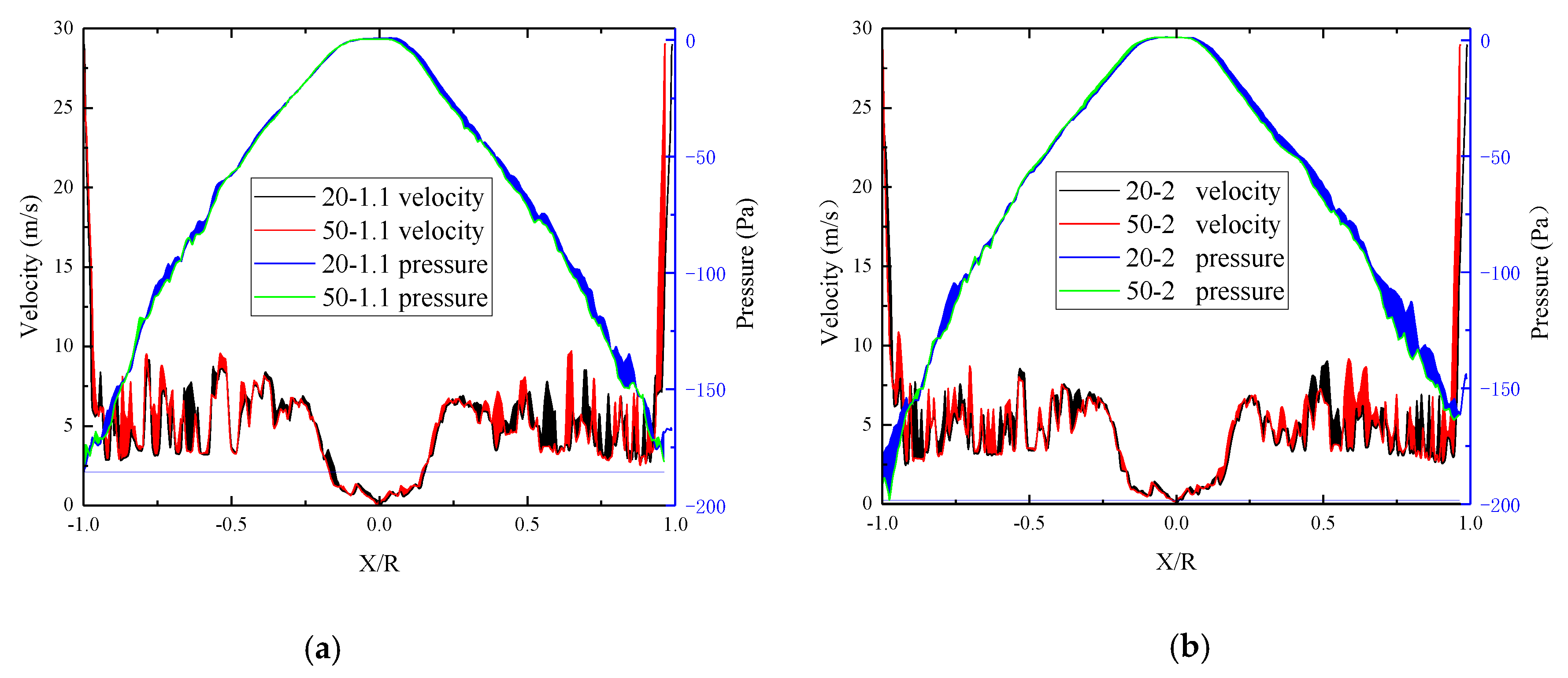
Figure 13 shows the pressure and velocity distribution of the upper surface of the rotor 4 (see Figure 1) with different configurations.
It is obvious that the velocity of the upper surface is non-uniformly distributed. The reasons for this are the periodic unsteady flow pulsation generated by the wake diffusion of the adjacent rotor and the interaction of various vortices. The negative pressure increases with an increase of the tilt angle. Moreover, the velocity and the pressure of the rotor surface with different configurations present different performances. For the same spacing, the pressure on the upper surface of the rotor is strongly influenced by the back rotor, while the increased tilt angle increases the overall velocity distributed over the upper surface. When the tilt angle is constant, the overall velocity of the upper surface decreases with an increased spacing which may lead a lower negative pressure. Considering that there is a large pressure gradient in the vortex, and each vortex is a distorted sub-region, it caused local pulsations of the angle of attack and pressure distribution as the blades pass.
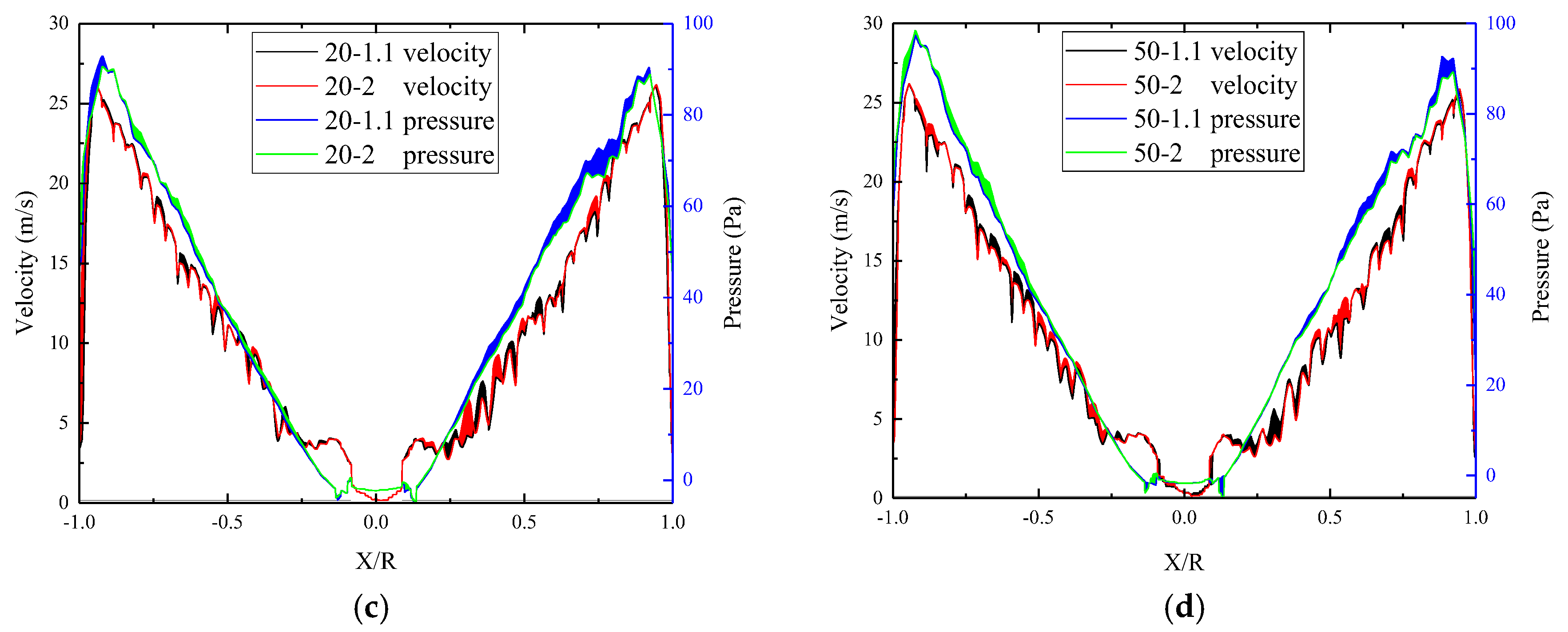
Figure 14 shows the velocity and pressure distribution of the lower surface of the rotor 4 (shown in Figure 1) with different configurations.
It is observed that velocity and pressure of the lower surface increase linearly along with the radius. The velocity of the lower surface increases slightly along with the tilt angle, and moderately decreases along with the spacing. The pressure increases obviously along with the increased tilt angle. The trend at 50 deg is more obvious than that of the 20 deg, which may cause the rotor thrust and torque to fluctuate periodically. Additionally, a larger tilt angle may affect the stability of the quadrotor to some extent.

4. Experimental Study

In order to verify the effectiveness of the CFD simulations and study the aerodynamic characteristics of the quadrotor with different spacing and tilt angle, a test bench was constructed in Figure 15.
The diameter of the rotor (NACA0012) is 400 mm with a chord length of 35 mm. The Reynolds number was approximately 1.1 × 10⁵. The test bench mainly included: (1) power system that could be changed using DC power supply (model: ACE GESHI lithium polymer battery), DC brushless motor (model: EM2835) and PWM (Pulse-Width Modulation) adjustment mode. (2) Measurement system to measure the rotational speed, the thrust, the power, the rotor spacing and the tilt angle of the rotor. The rotational speed was read by the photoelectric tachometer (Model: UT371, accuracy ± (0.04%n + 2d) r/min (1000–99,999)), the thrust was derived from a two-component balance, and the power was processed based on the recorded current and voltage values. The values of uncertainty that are presented in this study are all calculated for 95% confidence levels [30].
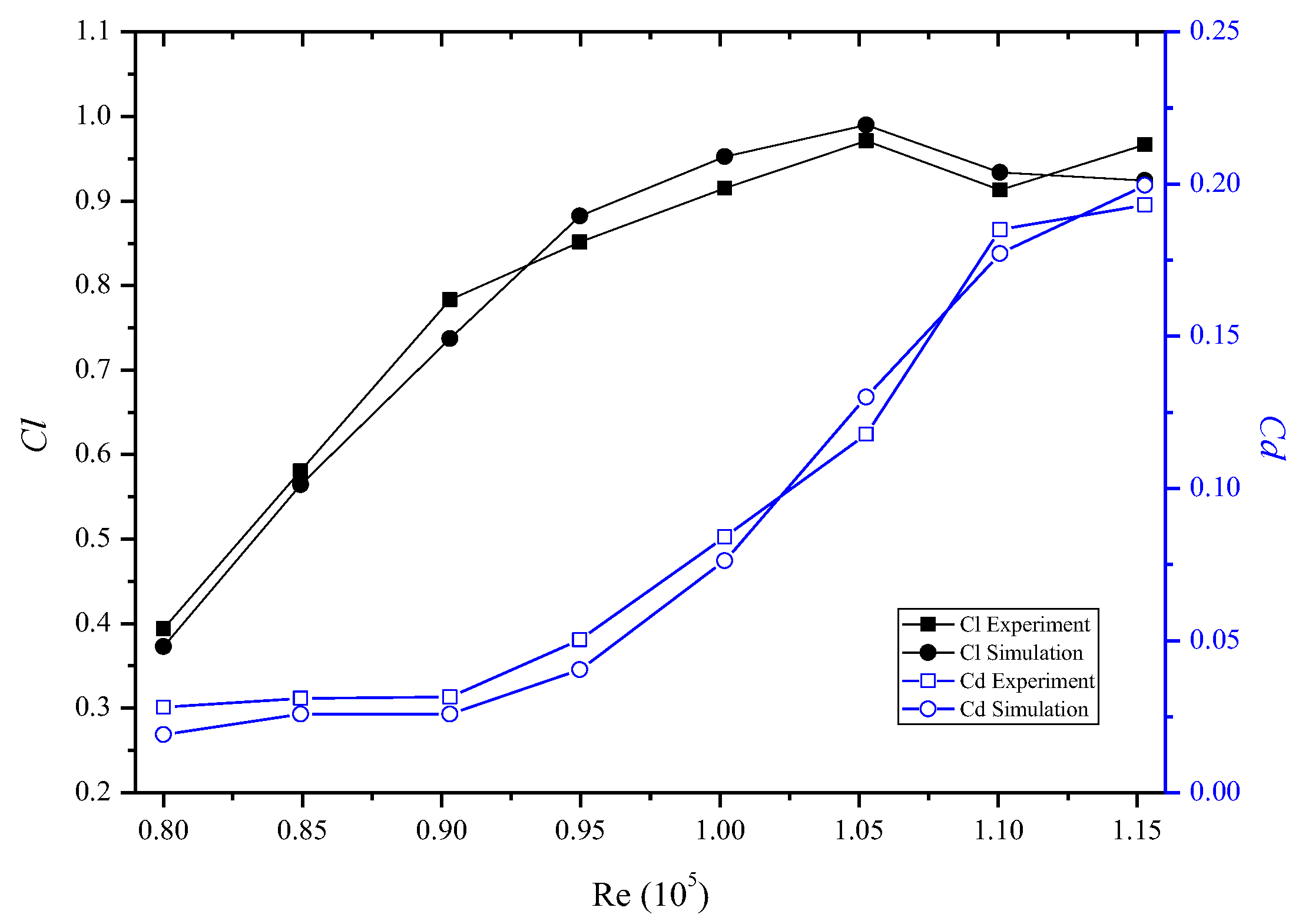
As a comparison, an isolated rotor is first analyzed to validate the effectiveness of the CFD methodology. The results have compared to experimental results as showed in Figure 16.
The comparison of lift coefficient Cl and drag coefficient Cd in experiment and simulation showed that they are generally in good agreement which means that the current study is efficient to handle the unsteady flow in the low Re environment.
Figure 17 shows the variation of the non-planar quadrotor thrust with different rotor spacing and tilt angle.
It can be seen that the thrust of the test is always greater than that in the simulation. This is because the record in the test is a periodically changing peak, that is, the maximum value, while the simulated thrust is taken from the average value in the stable period. However, the overall thrust increases with increased tilt angle and decreases to constant with increased spacing, which means that the trust is more affected by the tilt angle than the spacing. When the spacing is increased to 1.3–1.4 d, the thrust becomes stable. Moreover, the thrust of a non-planar quadrotor is always greater than the sum of four isolated rotors (up to 6.2%) which lead the conclusion that the non-planar quadrotor has good prospects in applications.
Figure 18 shows that the PL variation of the non-planar quadrotor.
As showed in the figure, the power loading of non-planar quadrotor decreases slightly with increased spacing. However, they are always lower than four isolated rotors. Since the tip vortex increases significantly with the increased tilt angle, the power consumption also increases to some extent. Thus, the thrust is improved, but the power consumption is correspondingly increased, especially at a larger tilt angle and smaller spacing. Therefore, the influences of tilt angle and spacing on power are similar to that of thrust. This is because the power is highly dependent on the resistance and the increased tip vortices attached to the rotor surface.
According to the power model of the non-planar quadrotor, the velocity V0 of the conventional planar quadrotor increases the slip velocity. It is caused by the moving wake and the tip vortex of each blade and reduced the inter-rotor interference. However, the non-planar quadrotor is in the tilting state, each rotor is in the flow field of the adjacent rotor, so there is a speed V0. For the face-to-face rotor pair, the speed V0 and the slip flow velocity is increased. Furthermore, the induced speed of the back-to-back rotor pair is also increased. Considering that the entire flow field is unsteady, and the vortex ring periodically scatters and re-enters the inflow of the rotor, the non-planar rotors may vibrate and cause a higher required power. Furthermore, this state will become more obvious with smaller rotor spacing and larger tilt angle.

5. Conclusions

In this paper, an aerodynamic model if non-planar quadrotor considering the mutual interference is established. The numerical simulation of an isolated single rotor and non-planar quadrotor along with the experiments demonstrate that the proposed model is able to better explain the unique aerodynamic interference of non-planar quadrotor. The conclusions of this paper are as follows:
(1)
The non-planar quadrotor rotor thrust will increase by 5–6% compared to the isolated rotor without interference. The tilt angle increased the actual induced velocity and outflow to increase the thrust of rotor;
(2)
The thrust becomes stable when the spacing is larger 1.4 d and the power is also significantly affected by the high-intensity vortex attached to the surface of the rotor and the tip vortex;
(3)
The flow field of the non-planar quadrotor is extremely complex, mainly based on unsteady flow caused by the intense outflow. There is a large pressure gradient in the vortex due to the periodic unsteady airflow pulsation generated by the rotor itself and the wake diffusion. Each vortex is a distorted sub-zone that causes the pressure distribution pulsations;
(4)
Power consumption of the non-planar quadrotor increases with the thrust which will cause a substantially balanced power loading. Moreover, the power loading of the non-planar quadrotor is less than the isolated rotors showed a better performance compared with the traditional planar rotors;
(5)
The unique aerodynamic performance of the non-planar quadrotor is significantly improved at a larger tilt angle with smaller spacing where the tip vortex is relatively strong, which is beneficial to optimize the multi-rotor system for the further studies.

Author Contributions

Y.L. carried out experiments and analyzed experimental results; J.W. wrote the manuscript with assistance of Y.L.

Funding

This research was supported by the National Natural Science Foundation of China, grant No. 51505087 and 51775114, the State Scholarship Fund from China Scholarship Council, grant number 201806655008, and Fujian Provincial Industrial Robot Basic Components Technology Research and Development Center, grant number 2014H21010011.

Acknowledgments

The authors thank the Key Laboratory of Fluid Power and Intelligent Electro-Hydraulic Control (Fuzhou University), Fujian Province University for applying the experimental field.

Conflicts of Interest

The authors declare no conflict of interest.

References

  1. Ryll, M.; Bülthoff, H.H.; Giordano, P.R. Modeling and control of a quadrotor UAV with tilting propellers. In Proceedings of the 2012 IEEE International Conference on Robotics and Automation, Saint Paul, MN, USA, 14–18 May 2012; pp. 4606–4613. [Google Scholar]
  2. Efraim, H.; Shapiro, A.; Weiss, G. Quadrotor with a Dihedral Angle: On the Effects of Tilting the Rotors Inwards. Int. J. Intell. Syst. 2015, 80, 313–324. [Google Scholar] [CrossRef]
  3. Elfeky, M.; Elshafei, M.; Saif, A.W.A.; Al-Malki, M.F. Quadrotor helicopter with tilting rotors: Modeling and simulation. In Proceedings of the 2013 World Congress on Computer and Information Technology (WCCIT), Sousse, Tunisia, 22–24 June 2013; pp. 1–5. [Google Scholar]
  4. Şenkul, A.F.; Altug, E. System Design of a Novel Tilt-Roll Rotor Quadrotor UAV. Int. J. Intell. Syst. 2015, 84, 1–25. [Google Scholar] [CrossRef]
  5. Senkul, A.F.; Altug, E. Modeling and control of a novel tilt-Roll rotor quadrotor UAV. In Proceedings of the 2013 International Conference on Unmanned Aircraft Systems, Atlanta, GA, USA, 28–31 May 2013; pp. 1071–1076. [Google Scholar]
  6. Ryll, M.; Bülthoff, H.H.; Giordano, P.R. A Novel Overactuated Quadrotor Unmanned Aerial Vehicle: Modeling, Control, and Experimental Validation. IEEE Trans. Control Syst. Technol. 2015, 23, 540–556. [Google Scholar] [CrossRef]
  7. Meng, J.D.; Zhao, Z.G. Modeling and Simulation of Microquadrotor UAV. J. Lanzhou Jiaotong Univ. 2013, 32, 63–67. [Google Scholar]
  8. Ferrarese, G.; Giulietti, F.; Avanzini, G. Modeling and Simulation of a Quad-Tilt Rotor Aircraft. IFAC Proc. Vol. 2013, 46, 64–70. [Google Scholar] [CrossRef]
  9. Salih, A.L.; Moghavvemi, M.; Mohamed, H.A.F.; Gaeid, K.S. Flight PID Controller Design for a UAV Quadrotor. Sci. Res. Essays 2010, 5, 3660–3667. [Google Scholar]
  10. Salih, A.L.; Moghavvemi, M.; Mohamed, H.A.F.; Gaeid, K.S. Modelling and PID Controller Design for a Quadrotor Unmanned Air Vehicle. In Proceedings of the 2010 IEEE International Conference on Automation, Quality and Testing, Robotics (AQTR), Cluj-Napoca, Romania, 28–30 May 2010; pp. 1–5. [Google Scholar]
  11. Li, J.; Li, Y. Dynamic Analysis and PID Control for a Quadrotor. In Proceedings of the International Conference on Mechatronics and Automation (ICMA), Beijing, China, 7–10 August 2011; pp. 573–578. [Google Scholar]
  12. Bouabdallah, S.; Siegwart, R. Backstepping and Sliding-Mode Techniques Applied to an Indoor Micro Quadrotor. In Proceedings of the 2005 IEEE International Conference on Robotics and Automation, Barcelona, Spain, 18–22 April 2005; pp. 2247–2252. [Google Scholar]
  13. Madani, T.; Benallegue, A. Backstepping Control for a Quadrotor Helicopter. In Proceedings of the IEEE/RSJ International Conference on Intelligent Robots and Systems, Beijing, China, 9–15 October 2006; pp. 3255–3260. [Google Scholar]
  14. Madani, T.; Benallegue, A. Backstepping Sliding Mode Control Applied to a Miniature Quadrotor Flying Robot. In Proceedings of the IECON 2006-32nd Annual Conference on IEEE Industrial Electronics, Paris, France, 6–10 November 2006; pp. 700–705. [Google Scholar]
  15. Turpin, M.; Michael, N.; Kumar, V. Trajectory Design and Control for Aggressive Formation Flight with Quadrotors. Auton. Robots 2012, 33, 143–156. [Google Scholar] [CrossRef]
  16. Huang, H.; Hoffmann, G.M.; Waslander, S.L.; Tomlin, C.J. Aerodynamics and Control of Autonomous Quadrotor Helicopters in Aggressive Maneuvering. In Proceedings of the IEEE International Conference on Robotics and Automation, Kobe, Japan, 12–17 May 2009; pp. 3277–3282. [Google Scholar]
  17. Yasuda, H.; Keiichi, K.; Yoshiaki, N. Numerical Analysis of Flow Field and Aerodynamic Characteristics of a Quadrotor. Trans. Jpn. Soc. Aeronaut. Space Sci. 2013, 11, 61–70. [Google Scholar] [CrossRef]
  18. Luo, J.; Zhu, L.; Yan, G. Novel Quadrotor Forward-Flight Model Based on Wake Interference. AIAA J. 2015, 53, 3522–3533. [Google Scholar] [CrossRef]
  19. Powers, C.; Mellinger, D.; Kushleyev, A.; Kothmann, B.; Kumar, V. Influence of Aerodynamics and Proximity Effects in Quadrotor Flight. Exp. Robot. 2013, 88, 289–302. [Google Scholar]
  20. Nguyen, H.; Liu, Y.; Koichi, M. Experimental Study for Aerodynamic Performance of Quadrotor Helicopter. Trans. Jpn. Soc. Aeronaut. Space Sci. 2018, 61, 29–39. [Google Scholar] [CrossRef] [Green Version]
  21. Kaya, D.; Kutay, T. Aerodynamic Modeling and Parameter Estimation of a Quadrotor Helicopter. In Proceedings of the AIAA Atmospheric Flight Mechanics Conference, Atlanta, GA, USA, 16–20 June 2014. [Google Scholar]
  22. Yeong, S.P.; Dol, S.S. Aerodynamic Optimization of Micro Aerial Vehicle. J. Appl. Fluid Mech. 2016, 9, 2111–2121. [Google Scholar] [CrossRef]
  23. Hwang, J.Y.; Min, K.J.; Kwon, O.J. Numerical Study of Aerodynamic Performance of a Multirotor Unmanned-Aerial-Vehicle Configuration. J. Aircr. 2014, 52, 839–846. [Google Scholar] [CrossRef]
  24. Leishman, J.G. Momentum Analysis in Forward Flight: Principles of Helicopter Aerodynamics, Fundamentals of Rotor Aerodynamics; Cambridge University Press: New York, NY, USA, 2006; p. 94. [Google Scholar]
  25. Seddon, J.; Newman, S. Basic Helicopter Aerodynamics; John Wiley & Sons: Hoboken, NJ, USA, 2011. [Google Scholar]
  26. Naidoo, Y.; Riaan, S.; Glen, B. Rotor aerodynamic analysis of a quadrotor for thrust critical applications. In Proceedings of the 4th Robotics and Mechatronics Conference of South Africa (ROBMECH 2011), Gauteng, South Africa, 23–25 November 2011. [Google Scholar]
  27. Johnson, W. Twin Rotor Interference in Forward Flight. In Helicopter Theory; Dover: New York, NY, USA, 1994; p. 142. [Google Scholar]
  28. Bohorquez, F.; Samuel, P.; Sirohi, J.; Pines, D.; Rudd, L.; Perel, R. Design, Analysis and Hover Performance of a Rotary Wing Micro Air Vehicle. J. Am. Helicopter Soc. 2003, 48, 80–81. [Google Scholar] [CrossRef]
  29. Jang, J.; Yang, G. Design of Wing Root Rotation Mechanism for Dragonfly-Inspired Micro Air Vehicle. Appl. Sci. 2018, 8, 1868. [Google Scholar] [CrossRef]
  30. Lei, Y.; Ji, Y.; Wang, C.; Bai, Y.; Xu, Z. Full-scale measurement on the aerodynamics of non-planar rotor pairs in a Hexacopter. J. Mech. Robot. 2017, 9, 064502. [Google Scholar] [CrossRef]
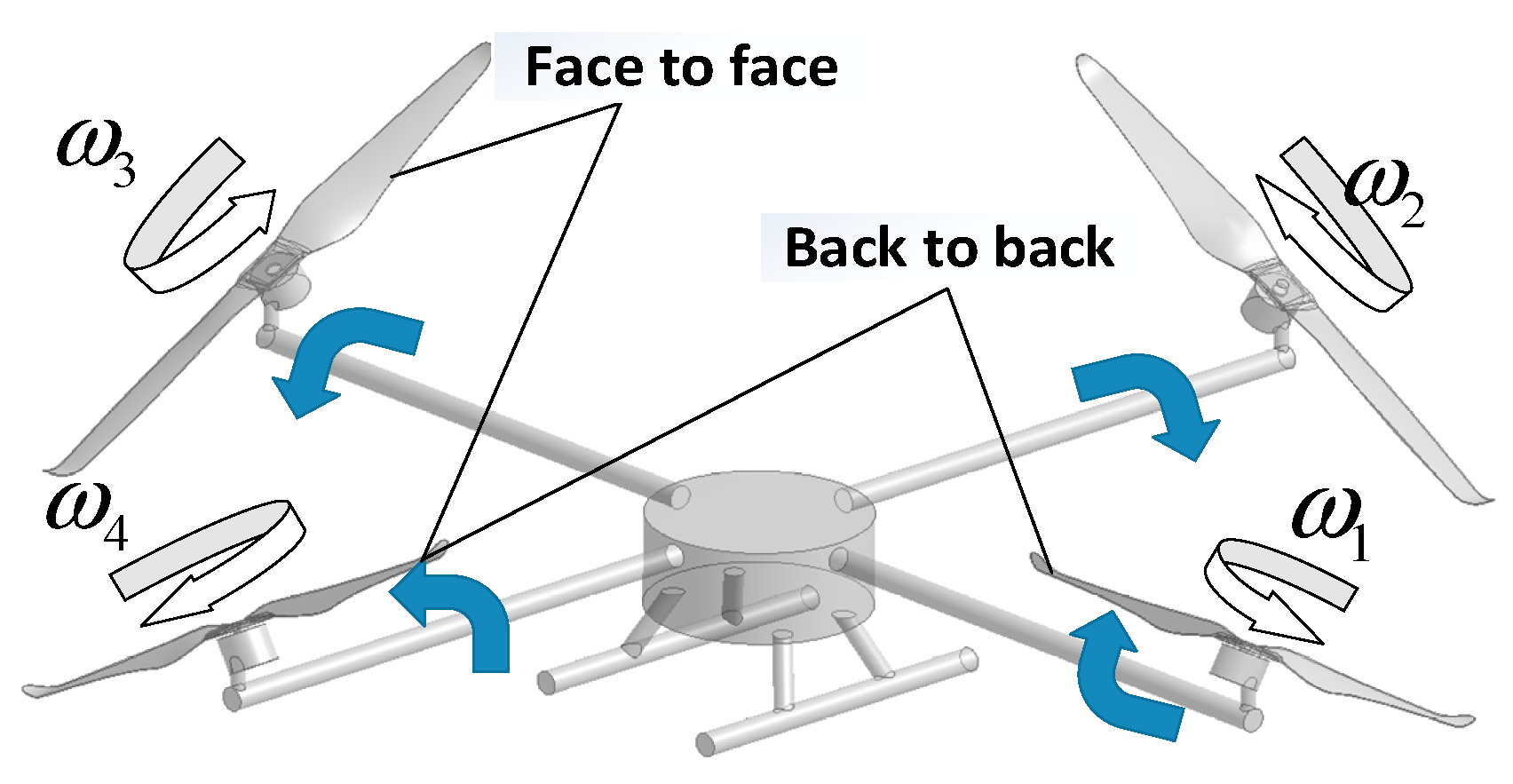
Figure 1. Schematic diagram of the non-planar quadrotor structure.
Applsci 09 02779 g001
Figure 2. Flow model of momentum theory analysis for the isolated rotor.
Applsci 09 02779 g002
Figure 3. Model of a blade element.
Applsci 09 02779 g003
Figure 4. Vector diagram for a section dr a length r away from the center of the propeller.
Applsci 09 02779 g004
Figure 5. Mesh distribution.
Applsci 09 02779 g005
Figure 6. Thrust variation of the isolated rotor.
Applsci 09 02779 g006
Figure 7. Simulation results of the isolated rotor: (a) Radial flow of an isolated rotor; (b) axial flow of an isolated rotor; (c) vortices distribution defined by the Q criterion at 55,840 s−2 and 816 s−2; (d) vertical velocity contour of the isolated rotor.
Applsci 09 02779 g007
Figure 8. The pressure and velocity contours of the planar quadrotor with rotor spacing of 1.05 d.
Applsci 09 02779 g008
Figure 9. The velocity distribution contours of typical non-planar configuration: (a) 10-1.1; (b) 50-1.1; (c) 10-2; (d) 50-2.
Applsci 09 02779 g009
Figure 10. Velocity vector distribution of planar rotors and non-planar rotors: (a) traditional planar rotors; (b) back-to-back non-planar rotors; (c) face-to-face non-planar rotors.
Applsci 09 02779 g010
Figure 11. Vorticity distribution of 816 s−2 defined by the Q criterion: (a) 50-1.2 (b) 50-1.6.
Applsci 09 02779 g011
Figure 12. Vorticity distribution defined by the Q criterion: (a) 73,040 s−2 at 30-1.1; (b) 73,037 s−2 at 30-1.2; (c) 132,047 s−2 at 50-1.2.
Applsci 09 02779 g012
Figure 13. Pressure and velocity distribution of the upper surface of rotor 4 with different configurations: (a) 20-1.1 and 50-1.1; (b) 20-2 and 50-2; (c) 20-1.1 and 20-2; (d) 50-1.1 and 50-2.
Applsci 09 02779 g013aApplsci 09 02779 g013b
Figure 14. Pressure and velocity distribution of the lower surface of rotor 4 with different configurations: (a) 20-1.1 and 50-1.1; (b) 20-2 and 50-2; (c) 20-1.1 and 20-2; (d) 50-1.1 and 50-2.
Applsci 09 02779 g014aApplsci 09 02779 g014b
Figure 15. Experimental setup.
Applsci 09 02779 g015
Figure 16. Comparison of experiment and simulation.
Applsci 09 02779 g016
Figure 17. Thrust variation of non-planar quadrotor.
Applsci 09 02779 g017
Figure 18. Power-loading of non-planar quadrotor.
Applsci 09 02779 g018