Article

Effect of the Inclination Angle on the Steady-State Heat Transfer Performance of a Thermosyphon

Key Laboratory of State Forestry and Grassland Administration on Forestry Equipment and Automation, School of Technology, Beijing Forestry University, Beijing 100083, China
*
Authors to whom correspondence should be addressed.
Appl. Sci. 2019, 9(16), 3324; https://doi.org/10.3390/app9163324
Submission received: 17 July 2019 / Revised: 2 August 2019 / Accepted: 9 August 2019 / Published: 13 August 2019

Abstract

:
A two-phase closed thermosyphon is an efficient heat transfer element. The heat transfer process of this type of thermosyphon includes conduction and convective heat transfer accompanied by phase changes. Variations in the inclination angle of a thermosyphon affect the steady-state heat transfer performance of the device. Therefore, the inclination angle is an important factor affecting the performance of a thermosyphon. In this paper, an equation for the actual heating area variations with respect to the inclination angle is deduced, and a model for the areal thermal resistance of a thermosyphon is proposed by analyzing the main influence mechanisms of the inclination angle on the heat transfer process. The experimental results show that the areal thermal resistance, which accounts for the effect of the actual heating area, does not change with respect to the inclination angle and exhibits a linear relationship with the heat transfer rate. The thermal resistance equation is fit according to the experimental data when the inclination angle of the thermosyphon is vertically oriented (90°), and the predicted values of the thermosyphon’s thermal resistance are obtained when the thermosyphon is inclined. The deviations between the experimental data and predicted values are less than ±0.05. Therefore, the theoretical equation can accurately predict the thermosyphon’s thermal resistance at different inclination angles.

1. Introduction

A two-phase closed thermosyphon is an important heat transfer element with an extremely high heat transfer coefficient [1]. These types of thermosyphons are widely used for aerospace applications [2], electronic device heat dissipation [3], room temperature control [4], cold storage control [5], geothermal energy utilization [6] and other applications. A two-phase closed thermosyphon is usually a closed metal tube filled with a certain proportion of a liquid working fluid. The latent heat of the working fluid phase change can provide a large amount of energy for heat transfer. The reflux of the working fluid depends on gravity and does not require a wick [7,8]. The thermosyphon is divided into three sections along the axis from the bottom to the top: the evaporation section, the adiabatic section and the condensation section. The working fluid in the thermosyphon liquid pool undergoes phase transformation in the evaporation section, transforms into a gaseous working fluid, transfers heat to the condensation section, releases latent heat into the liquid working fluid, and completes the cycle via gravity reflux to the evaporation section [5,7,9].
To better understand the heat transfer characteristics of a thermosyphon and the influence of various parameters on its performance, a large number of papers have performed studies using experimental and numerical simulation methods. Noie et al. [10] studied the influence of the inclination angle on the thermal performance of two-phase closed thermosyphons with different filling rates under normal working conditions. They performed a series of experiments using copper thermosyphons and reported observations of the geyser boiling phenomenon, which had no restriction on the heat transfer performance of the thermosyphon but could potentially damage the end cover of the condenser. Lee et al. [11] performed an experimental study on the heat transfer performance of a two-phase closed thermosyphon with water and Freon-11 as the working fluids, and conducted a simple theoretical analysis of the maximum heat transfer capacity of this thermosyphon. The effects of the filling rate, heating length-to-cooling length ratio, working pressure, heat flux, and working fluid on the thermosyphon’s heat transfer performance were studied. Noie et al. [12] experimentally studied the steady-state heat transfer characteristics of thermosyphons with different values of heat transfer power, liquid filling rate, and evaporation section aspect ratio. The experimental boiling heat transfer coefficients were compared to existing correlation coefficients, and the optimum liquid filling rate was determined at a certain aspect ratio. Payakaruk et al. [13] studied the effects of various dimensionless parameters on the heat transfer characteristics of thermosyphons. They performed experimental tests of copper thermosyphons with different geometrical sizes, filling rates, and inclination angles to determine the effects of the various dimensionless parameters on the heat transfer rate and total thermal resistance. Wang et al. [14] developed a flat thermosyphon with a transparent wall and a visual experimental system to study the vapor–liquid two-phase behaviors and thermal performance. The results show that the motion of the bubbles causes strong liquid disturbance, leading to the enhancement of convective boiling and condensation heat transfer. With increasing heat flux, the motion of bubbles disturbs the liquid working fluid and the condensation film becomes stronger, resulting in better thermal performance for the flat tow-phase thermosyphon. Solomon et al. [15] anodized the surface of the evaporation section of a two-phase closed thermosyphon, thereby improving the heat transfer coefficient of the evaporation section. Compared to a nonanodized two-phase closed thermosyphon, the total thermal resistance of the anodized thermosyphon at horizontal, inclined, and vertical positions decreased by 17%, 20%, and 23%, respectively.
Huminic et al. [16] used iron oxide-nanofluids as working fluids to study the effects of different parameters on the thermal performance of two-phase closed thermosyphons, wherein they focused on the heat transfer rate, evaporative condensation heat transfer coefficient, and thermal resistance. They experimentally studied different working fluid nanoparticle concentrations, working temperatures, and thermosyphon inclination angles. In addition, they compared the performance provided by the nanofluid to that provided by pure water. Arya et al. [17] studied the effects of different operating parameters such as heat flux, carbon nanotube (CNT) mass concentration, and working fluid filling ratio on the thermal performance and thermal resistance of the flat heat pipe. The results show that, with increasing heat flux, the heat transfer coefficient of the heat pipe evaporator section increases, and the heat transfer coefficient of CNT/water is 40% greater than that of deionized water. CNTs change the contact angle between the liquid and surface by forming a fouling layer on the screen structure and enhancing the capillary force and thermal performance of the structure. Lv et al. [18] systematically studied the effect of the liquid filling rate on the thermal performance of a thin novel flat heat pipe (FHP) heat exchanger under natural convection conditions. Their results showed that the composite material had an optimum filling range, and the temperature difference was very small. Therefore, the FHP heat exchanger exhibited good thermal diffusivity. Zhao et al. [19] used computational fluid dynamics (CFD) to study the transient thermal performance of phase change and heat and mass transfer in a two-phase closed thermosyphon. A CFD model based on fluid volume technology was established. The working fluid was deionized water. The CFD model reproduces the evaporation and condensation processes of the thermosyphon under different heating inputs. By increasing heating input, the thermal resistance decreases to the minimum (0.552 K/W) and the effective thermal conductivity increases to the maximum (2.07 × 10⁶ W/m·K). Alammar et al. [20] used Fluent to study the influence of the filling rate and thermosyphon inclination angle on the thermal performance of a thermosyphon and then compared the computational fluid dynamics (CFD) simulation results with experimental data. Their results showed that the maximum deviations of the temperature distribution and thermal resistance were 4.2% and 8.1%, respectively, and the evaporator temperature increased significantly at low filling rates and low inclination angles. Ahmed et al. [21] performed a comprehensive study of the boiling characteristics of geysers in two-phase closed thermosyphons with water as the working fluid at different inclinations and filling rates. The results showed that the inclination angle and liquid filling rate had significant effects on the occurrence and cycle of geyser boiling under high heat input conditions.
The inclination angle is the angle between the horizontal plane and the thermosyphon axis, and this angle has an important influence on the heat transfer characteristics of a thermosyphon [10,15,21]. In the literature [15], the evaporator heat transfer coefficient of the thermosyphon can be increased by 33% by choosing the appropriate inclination angle. Previous studies have explained the effects of various factors on thermosyphons through experimental phenomena or simulation data, but no good theories that explain the response of the effects and predict the thermal resistance value have been presented. In this paper, by analyzing the main influencing factors of the inclination angle, a formula for calculating the actual heating area is deduced, and a theory for the areal thermal resistance is proposed, providing a research method for studying the heat transfer characteristics of thermosyphons.

2. Theory

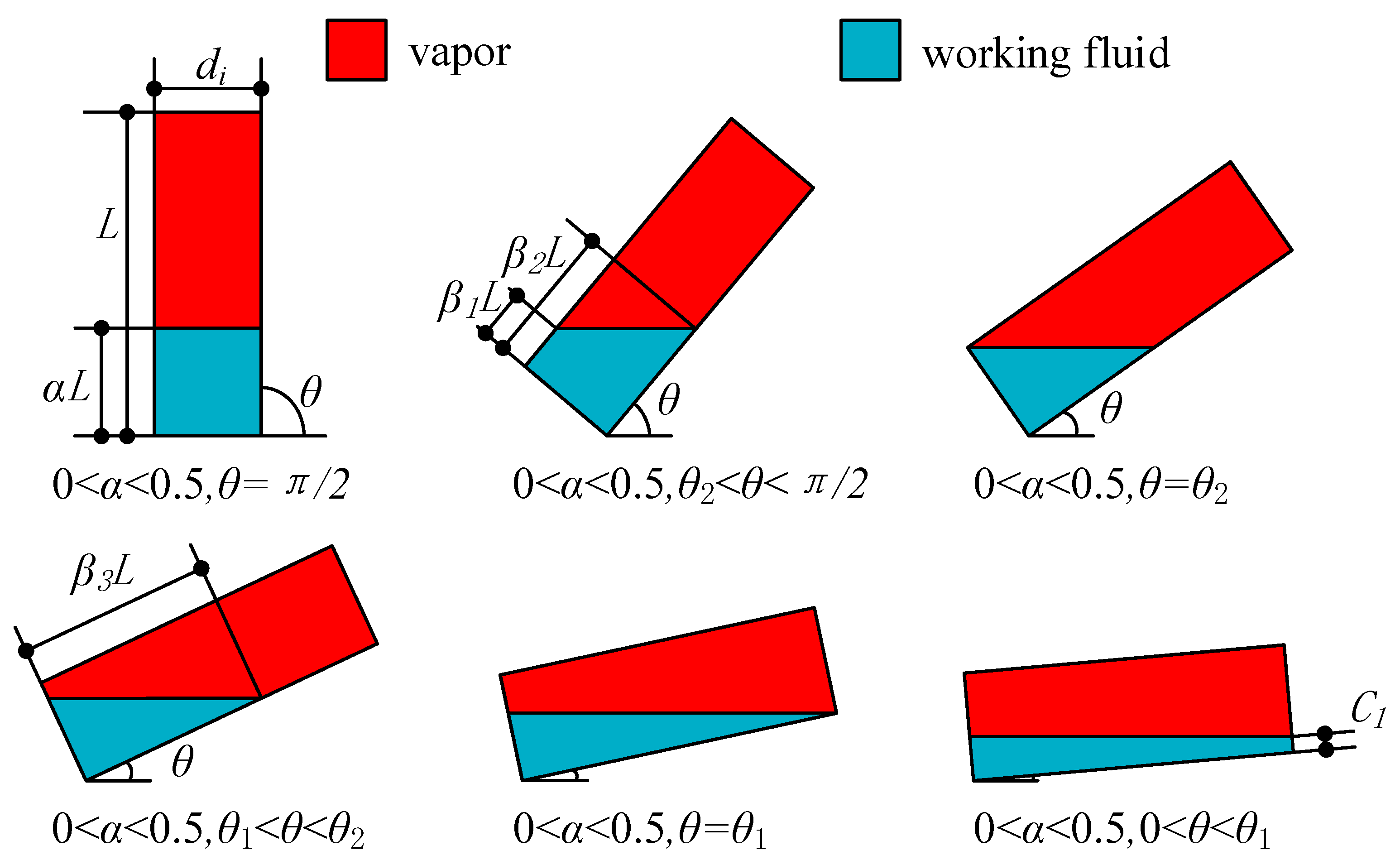
2.1. Actual Heating Area

The angle between the horizontal plane and the axis direction of the thermosyphon is called the inclination angle, which has an important influence on the heat transfer characteristics of a thermosyphon under steady-state operation. The contact area between the working fluid and inner wall in the thermosyphon liquid pool is called the actual heating area. Changes in the inclination angle will cause changes in the actual heating area, thereby affecting the heat transfer characteristics of a thermosyphon. According to the different filling rates α (ratio of working fluid volume to inner volume of the thermosyphon), heating length ratios β (ratio of evaporation length to total length) and inclination angles θ (angle between the horizontal plane and the thermosyphon axis), the actual heating area of a thermosyphon is discussed in 12 cases. Figure 1 and Figure 2 are sketches of a thermosyphon and some parameters used in the theoretical derivation.
When 0 < α < 0.5, the two critical limits of the inclination angle are calculated first. These critical limits are the inclination angle θ2, which occurs when the liquid surface contacts the bottom surface of the thermosyphon; and the inclination angle θ1, which occurs when the liquid surface contacts the upper surface of the thermosyphon. Two critical values can be determined according to the invariant property of V (working fluid volume) in the thermosyphon inclination process.
The value of θ2 is determined as follows:
tan θ 2 = d i 2 α L
The value of θ1 is determined as follows:
V = α L π d i 2 4 = d i 3 8 tan θ 1 [ t arccos t ( 1 t 2 ) 1 2 + 1 3 ( 1 t 2 ) 3 2 ] 1 2 L tan θ 1 d i 1
There exists a minimum distance of β1 and a maximum distance of β2 from the working fluid level to the bottom of the thermosyphon when α and θ are in the following range:
0 < α < 1 2 , θ 2 θ π 2
β 1 L = α L d i 2 tan θ
β 2 L = α L + d i 2 tan θ
(a) The first case occurs when the following conditions are met:
0 < α < 1 2 , θ 2 θ π 2 , 0 < β L < β 1 L
In this scenario, the actual heating area can be calculated using the following formula:
A θ = β L π d i
(b) The second case occurs when the following conditions are met:
0 < α < 1 2 , θ 2 θ π 2 , β 1 L β L < β 2 L
In this scenario, the actual heating area can be calculated using the following formula:
A θ = β L π d i + d i 2 2 tan θ [ t arccos t ( 1 t 2 ) 1 2 ] 1 2 ( α β ) L tan θ d i
(c) The third case occurs when the following conditions are met:
0 < α < 1 2 , θ 2 θ π 2 , β 2 L β L L
In this scenario, the actual heating area can be calculated using the following formula:
A θ = α L π d
Furthermore, there is a maximum distance of β3 from the working fluid level to the bottom of the thermosyphon when α and θ are in the following range:
0 < α < 1 2 , θ 1 θ < θ 2
V = α L π d i 2 4 = d i 3 8 tan θ [ t arccos t ( 1 t 2 ) 1 2 + 1 3 ( 1 t 2 ) 3 2 ] 1 2 β 3 L tan θ d i 1
(d) The fourth case occurs when the following conditions are met:
0 < α < 1 2 , θ 1 θ < θ 2 , 0 < β L < β 3 L
In this scenario, the actual heating area can be calculated using the following formula:
A θ = d i 2 2 tan θ [ t arccos t ( 1 t 2 ) 1 2 ] 1 2 β 3 L tan θ d i 1 2 ( β 3 L β L ) tan θ d i
(e) The fifth case occurs when the following conditions are met:
0 < α < 1 2 , θ 1 θ < θ 2 , β 3 L β L L
In this scenario, the actual heating area can be calculated using the following formula:
A θ = d i 2 2 tan θ [ t arccos t ( 1 t 2 ) 1 2 ] 1 2 β 3 L tan θ d i 1
Each inclination angle θ corresponds to a constant C1 when α and θ are in the following range:
0 < α < 1 2 , 0 θ < θ 1
To easily solve this problem, the value of C1 is determined first. When θ = 0, C1 can be directly obtained. When θ ≠ 0, C1 can be calculated using the following formula:
V = α L π d i 2 4 = d i 3 8 tan θ [ t arccos t ( 1 t 2 ) 1 2 + 1 3 ( 1 t 2 ) 3 2 ] 1 2 ( C 1 + L tan θ ) d i 1 2 C 1 d i
(f) The sixth case occurs when the following conditions are met:
0 < α < 1 2 , 0 < θ < θ 1 , 0 < β L L
When θ = 0, the actual heating area can be directly calculated. When θ ≠ 0, the actual heating area can be calculated using the following formula:
A θ = d i 2 2 tan θ [ t arccos t ( 1 t 2 ) 1 2 ] 1 2 ( C 1 + L tan θ ) d i 1 2 ( C 1 + L tan θ β L tan θ ) d i
When 0.5 ≤ α ≤ 1, the two critical limits of the inclination angle are calculated first. These critical limits are the inclination angle θ4, which occurs when the liquid surface contacts the upper surface of the thermosyphon, and the inclination angle θ3, which occurs when the liquid surface contacts the bottom surface of the thermosyphon. Two critical values can be determined according to the invariant property of V in the inclination process of the thermosyphon.
The value of θ4 is determined as follows:
tan θ 4 = d i 2 ( 1 α ) L
The value of θ3 is determined as follows:
V = ( 1 α ) L π d i 2 4 = d i 3 8 tan θ 3 [ t arccos t ( 1 t 2 ) 1 2 + 1 3 ( 1 t 2 ) 3 2 ] 1 2 L tan θ 3 d i 1
There exists a minimum distance of β4 and a maximum distance of β5 from the working fluid level to the bottom of the thermosyphon, when α and θ are in the following range:
1 2 α 1 , θ 4 θ π 2
β 4 L = α L d i 2 tan θ
β 5 L = α L + d i 2 tan θ
(g) The seventh case occurs when the following conditions are met:
1 2 α 1 , θ 4 θ π 2 , 0 β L < β 4 L
In this scenario, the actual heating area can be calculated using the following formula:
A θ = β L π d i
(h) The eighth case occurs when the following conditions are met:
1 2 α 1 , θ 4 θ π 2 , β 4 L β L < β 5 L
In this scenario, the actual heating area can be calculated using the following formula:
A θ = β L π d i + d i 2 2 tan θ [ t arccos t ( 1 t 2 ) 1 2 ] 1 2 ( α β ) L tan θ d i
(i) The ninth case occurs when the following conditions are met:
1 2 α 1 , θ 4 θ π 2 , β 5 L β L L
In this scenario, the actual heating area can be calculated using the following formula:
A θ = α L π d i
There is a maximum distance of β6 from the working fluid level to the upper end of the thermosyphon, when α and θ are in the following range:
1 2 α 1 , θ 3 θ < θ 4
V = ( 1 α ) L π d i 2 4 = d i 3 8 tan θ [ t arccos t ( 1 t 2 ) 1 2 + 1 3 ( 1 t 2 ) 3 2 ] 1 2 β 6 L tan θ d i 1
(j) The tenth case occurs when the following conditions are met:
1 2 α 1 , θ 3 θ < θ 4 , 0 β L < ( 1 β 6 ) L
In this scenario, the actual heating area can be calculated using the following formula:
A θ = β L π d i
(k) The eleventh case occurs when the following conditions are met:
1 2 α 1 , θ 3 θ < θ 4 , ( 1 β 6 ) L β L L
In this scenario, the actual heating area can be calculated using the following formula:
A θ = β L π d i d i 2 2 tan θ [ t arccos t ( 1 t 2 ) 1 2 ] 1 2 ( β + β 6 1 ) L tan θ d i 1
Each inclination angle θ corresponds to a constant C2 when α and θ are in the following range:
1 2 α 1 , 0 θ < θ 3
To easily solve this problem, the value of C2 is determined first. When θ = 0, C2 can be directly obtained. When θ ≠ 0, C2 can be calculated using the following formula:
V = ( 1 α ) L π d i 2 4 = d i 3 8 tan θ [ t arccos t ( 1 t 2 ) 1 2 + 1 3 ( 1 t 2 ) 3 2 ] 1 2 ( C 2 + L tan θ ) d i 1 2 C 2 d i
(l) The twelfth case occurs when the following conditions are met:
1 2 α 1 , 0 < θ < θ 3 , 0 β L L
When θ = 0, the actual heating area can be directly calculated. When θ ≠ 0, the actual heating area can be calculated using the following formula:
A θ = β L π d i d i 2 2 tan θ [ t arccos t ( 1 t 2 ) 1 2 ] 1 2 ( C 2 + β L tan θ ) d i 1 2 C 2 d i
In this paper, 12 cases of actual heating areas at different inclinations are deduced theoretically, and the results are summarized in Table 1.

2.2. Total Thermal Resistance and Areal Thermal Resistance
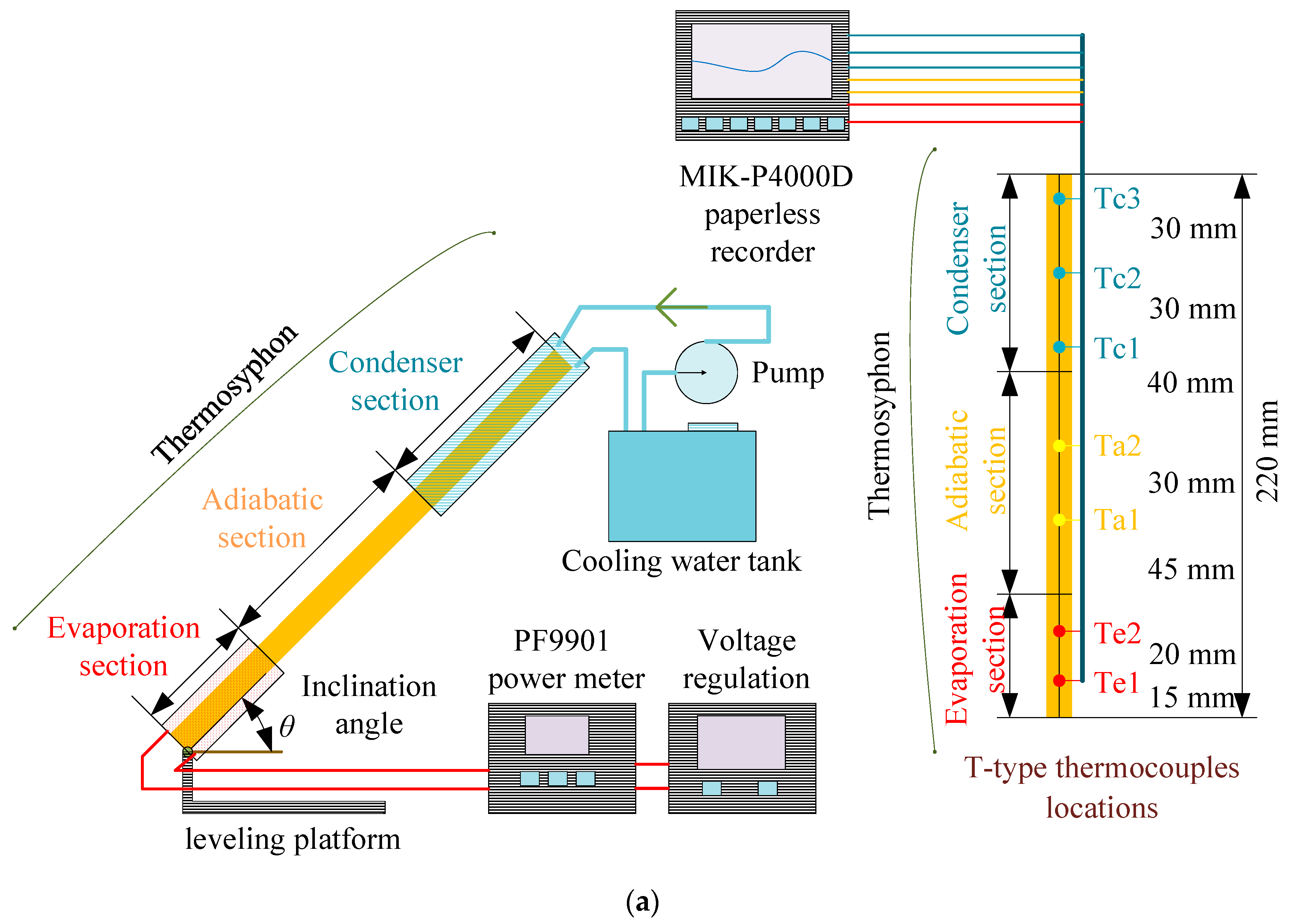
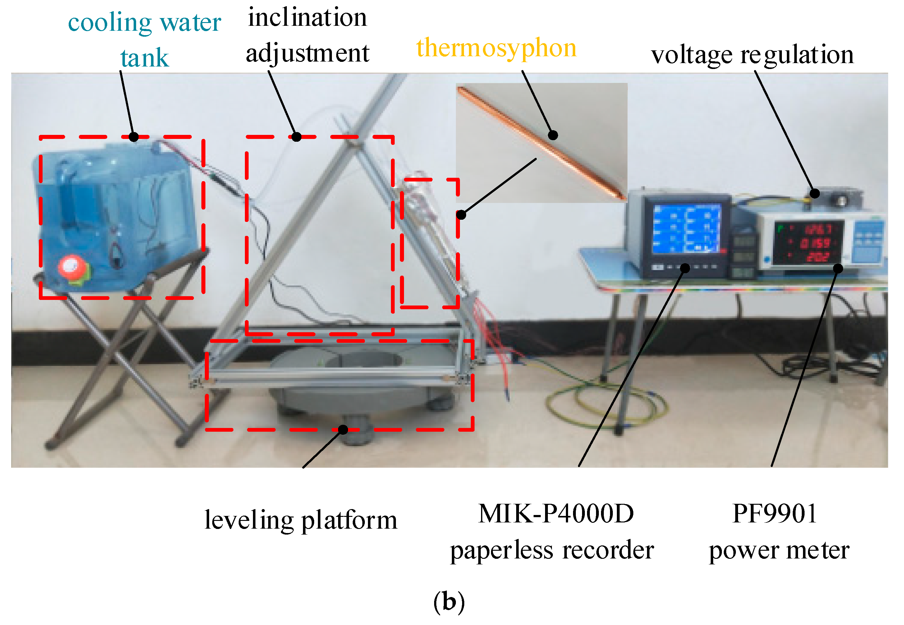
In the theory of heat transfer, thermal resistance is often used to characterize the heat transfer performance of objects, and the heat transfer characteristics of objects are analyzed according to the variations in thermal resistance with respect to external conditions. The total thermal resistance of a thermosyphon is equal to the ratio of the heat transfer rate to the temperature difference between the evaporation section and condensation section.
R = Δ T Q
The areal thermal resistance is the value of thermal resistance per unit area. In this paper, the areal thermal resistance of a thermosyphon is defined as the product of the total thermal resistance and the actual heating area. Therefore, the areal thermal resistance of a thermosyphon can be expressed as follows:
R A = Δ T A θ Q

3. Experiments

In the experiments, the evaporation section of the thermosyphon was heated by an alternating current (AC) heating rod, and the condensation section was cooled with water. A cylindrical copper two-phase closed thermosyphon with ethanol as the working fluid was selected as the test object. The thermosyphon had a total length of 220 mm, an evaporation section length of 50 mm, an insulation section length of 90 mm, a condensation section length of 80 mm, internal and external diameters of 7.6 mm and 10 mm, respectively, and a filling rate of 0.227. The specific parameters of the thermosyphon are listed in Table 2.
Figure 3 shows a schematic diagram of the thermosyphon experimental device and a physical diagram of the experimental device. The whole system is divided into five parts: the heating part, the heat pipe part, the cooling part, the inclination adjustment part and the temperature acquisition part. The heating part is mainly composed of a voltage regulating module, a power meter and a heating rod. The heat input is controlled by adjusting the AC voltage supply of the heating rod with an electronic voltage regulating module, and the corresponding power is determined using a PF9901 power meter. The heat pipe part and the thermocouple of the temperature acquisition part are fixed together. Seven T-type thermocouples are arranged along the axis on the outer side of the thermosyphon, and they are located 15 mm, 35 mm, 80 mm, 110 mm, 150 mm, 180 mm and 210 mm from the bottom of the thermosyphon. The specific locations are shown in Figure 3a. Temperature data are collected using an MIK-P4000D paperless recorder. In the cooling part, a circulating pump is used to drive cooling liquid circulation in the cooling water tank to cool the condensation section of the thermosyphon. By adding cold water, the temperature of cooling water is kept at 14 ± 2.4 °C. The support device of the inclination adjustment part is placed on a leveling platform to ensure that the bottom of the mechanical device equipped with the thermosyphon is in a horizontal state. The inclination of the thermosyphon relative to the horizontal plane is adjusted by changing the fixed position of the support rod. Ceramic fiber paper is wrapped on the outside of the heat pipe part to reduce heat loss and the influence of changes in the temperature of the external environment on the system.
In this experiment, the selected working inclination angles are 15°, 30°, 45°, 60°, 75° and 90°. The heating power values used for each working inclination angle are 20 W, 30 W, 40 W, 50 W, and 60 W, respectively. The temperature distributions of 30 working states were measured, and the temperature values of each section were expressed as the arithmetic average of the thermocouple values.
To calculate the uncertainty of the whole experiment, the theory introduced in reference [22] was used:
Δ Y = ( Y x 1 Δ x 1 ) 2 + ( Y x 2 Δ x 2 ) 2 + ( Y x 3 Δ x 3 ) 2 +
where, Y is a function of the independent parameters x1, x2, x3, …, xn, and Δx1, Δx2, Δx3, …, Δxn is the uncertainty of the independent parameters that can be obtained from the instrument. The uncertainty values of the instruments used in the experiment are as follows: AC frequency accuracy (±0.1%), power meter accuracy (±0.5%) and T-type thermocouple (±0.5 °C).

4. Results and Discussion

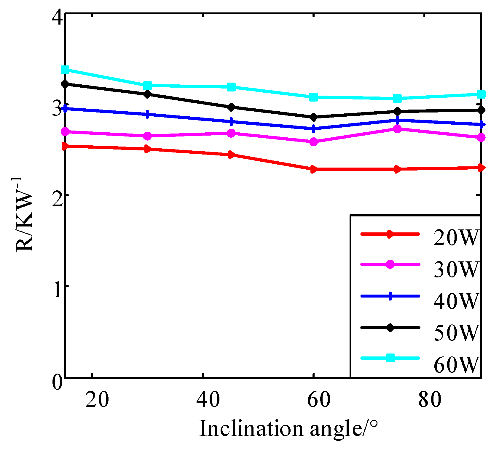
4.1. Variations in the Total Thermal Resistance and Areal Thermal Resistance of the Thermosyphon with Respect to the Inclination Angle

Figure 4 shows the response of the total thermal resistance with respect to the inclination angle when the thermosyphon is operating under steady-state heat transfer conditions. When the inclination angle is less than 60°, the thermal resistance of the thermosyphon decreases with increasing inclination angle. When the inclination angle is greater than 60°, the change in thermal resistance with the inclination angle is relatively slow. These phenomena occur because, when the inclination angle is small, increasing the inclination angle can obviously increase the actual heating area of the evaporation section of the thermosyphon and increase the gravitational component of the working fluid reflux. In contrast, when the inclination angle is sufficiently large, the gravitational force can provide power for working fluid reflux. Therefore, further increases in the inclination angle have little effect on thermal resistance. When the heat transfer power is 30 W, 40 W or 50 W, the thermal resistance is minimized when the inclination angle is 60°. This minimum value occurs because there is sufficient gravitational force to promote the working fluid reflux, and the stratified flow of gas and liquid avoids the rising gas obstructing the working fluid reflux. The change in thermal resistance with inclination angle is in accordance with the results already published in the literature [15].
Figure 5 shows the response of the thermosyphon’s areal thermal resistance with respect to the inclination angle. Overall, the areal thermal resistance does not decrease or increase with variations in the inclination angle because the areal thermal resistance is affected by the change in actual heating area generated by the change in inclination angle. Both the total thermal resistance and areal thermal resistance increase with increasing heat transfer rate.

4.2. Variations in the Total Thermal Resistance and Areal Thermal Resistance of the Thermosyphon with Respect to the Heat Transfer Rate

Figure 6 shows the response of the total thermal resistance of the thermosyphon with respect to the heat transfer rate under steady-state conditions. The general trend of the total thermal resistance of the thermosyphon is to increase with the increasing heat transfer rate, and the thermal resistance at an inclination angle of 15°, which is greater than those at other inclinations. This maximum value of thermal resistance occurs at 15° because the actual heating area of the thermosyphon’s evaporation section of the thermosyphon is the smallest at this angle, and the gravitational component driving the refrigerant reflux is the smallest when the inclination angle is small. This result is in accordance with the results already published in the literature [17,23].
Figure 7 shows the response of the areal thermal resistance of the thermosyphon with respect to the heat transfer rate. The variations in the areal thermal resistance with respect to the heat transfer rate are consistent at all inclination angles, indicating that the working inclination angle has little effect on the areal thermal resistance. The overall trend of the areal thermal resistance of the thermosyphon is to increase with increasing heat transfer power, which is linearly related to the heat transfer rate.

4.3. Derivation and Verification of the Theoretical Formula for the Total Thermal Resistance of the Thermosyphon

Figure 8 shows a primary curve fitting of the areal thermal resistance and heat transfer rate of the thermosyphon, which has a goodness of fit R2 of 0.9892. Two dashed lines are drawn. These lines correspond to a confidence level of 95%. The results show that the areal thermal resistance values are within the two dashed lines. Thus, the areal thermal resistance of the thermosyphon can be expressed by this fitting line when the significance level is 0.05.
The fitting equation (Equation (46)) of the total thermal resistance with respect to the inclination angle and heat transfer rate can be obtained by using the data measured when the thermosyphon is placed vertically as fitting values and then combining Equations (9), (43) and (44).
R = R A A θ = R S Q + R C β L π d i d i 2 2 tan θ = 23.12 Q + 2358 380 π 28.88 tan θ
According to the fitting equation (Equation (46)), the total thermal resistance of the inclined thermosyphon is predicted and compared with the experimental values, and the results are presented in Figure 9 and Table 3. The deviations between the predicted data and the experimental data are within ±0.05, showing that the theoretical equation can accurately predict the total thermal resistance of the thermosyphon at different inclination angles.

5. Conclusions

By analyzing the main influencing factors of the inclination angle on the heat transfer resistance of a two-phase closed thermosyphon, a formula for the actual heating area is deduced, and a model for the areal thermal resistance of a thermosyphon is proposed. An experimental system was established, where the inclination angles of a copper two-phase closed thermosyphon with ethanol as the working fluid were 15°, 30°, 45°, 60°, 75°, and 90°, and the heat transfer rates were 20 W, 30 W, 40 W, 50 W, and 60 W.
(1) The actual heating area of a thermosyphon is defined as the contact area between the working fluid in the liquid pool and the inner wall of the thermosyphon, which is part of the heater. Based on the discussion of the three parameters of filling rate, heating length and inclination angle, the formulas for the actual heating area in 12 cases are obtained.
(2) The areal thermal resistance of the thermosyphon is defined by Equation (44). The results show that the areal thermal resistance does not change with the inclination angle, and the areal thermal resistance is linearly related to the heating power. This phenomenon occurs because the areal thermal resistance accounts for the effect of the inclination angle on the actual heating area. The main reason for the influence of the inclination angle on the heat transfer resistance of the thermosyphon is that the inclination angle changes the actual heating area of the evaporation section.
(3) The total thermal resistance equation (Equation (46)) was fitted with the measured data from the vertically oriented thermosyphon, and the predicted values of the total thermal resistance were obtained when the thermosyphon was placed in an inclined position. Upon comparison, it is found that the deviations between the predicted values and the experimental values are within ±0.05, indicating that the areal thermal resistance theory can accurately predict the total thermal resistance of a thermosyphon at different inclination angles.

Author Contributions

All authors contributed to the paper. W.L., provided guidance, supervision, and revised the paper; Y.W., designed the research, conceived the idea of the study, and wrote the paper; Y.W. and Z.Z., performed the experiment and discussed experimental results; Y.W. and D.X., discussed the experimental results and revised the paper. All authors read and approved the final manuscript.

Funding

The authors gratefully acknowledge the financial support from the National Science Foundation of China (31670716), the China Postdoctoral Science Special Foundation (2016T90044) and the China Postdoctoral Science Foundation (2015M570945).

Conflicts of Interest

The authors declare no conflict of interest.

Nomenclature

diinner diameter (m)
Llength (m)
αfilling rate
Vworking fluid volume (m3)
βheater length ratio
θinclination angle (rad)
Aθactual heating area at inclination (m2)
Aheating area (m2)
ΔTtemperature difference (K)
Qheat transfer rate (W)
Rthermal resistance (KW−1)
RAarea thermal resistance (m2KW−1)
RSthermal resistance increment (m2KW−2)
RCconstant thermal resistance (m2KW−1)

References

  1. Nada, S.A.; El-Ghetany, H.H.; Hussein, H.M.S. Performance of a two-phase closed thermosyphon solar collector with a shell and tube heat exchanger. Appl. Therm. Eng. 2004, 24, 1959–1968. [Google Scholar] [CrossRef]
  2. Riehl, R.R.; Dutra, T. Development of an experimental loop heat pipe for application in future space missions. Appl. Therm. Eng. 2005, 25, 101–112. [Google Scholar] [CrossRef]
  3. Li, J.; Wang, D.; Peterson, G.P.B. A Compact Loop Heat Pipe with Flat Square Evaporator for High Power Chip Cooling. IEEE Trans. Compon. Packag. Manuf. Technol. 2011, 1, 519–527. [Google Scholar] [CrossRef]
  4. Du, J.; Bansal, P.; Huang, B. Simulation model of a greenhouse with a heat-pipe heating system. Appl. Energy 2012, 93, 268–276. [Google Scholar] [CrossRef]
  5. Singh, R.; Mochizuki, M.; Mashiko, K.; Nguyen, T. Heat pipe based cold energy storage systems for datacenter energy conservation. Energy 2011, 36, 2802–2811. [Google Scholar] [CrossRef]
  6. Ahmadzadehtalatapeh, M.; Yau, Y.H. The application of heat pipe heat exchangers to improve the air quality and reduce the energy consumption of the air conditioning system in a hospital ward—A full year model simulation. Energy Build. 2011, 43, 2344–2355. [Google Scholar] [CrossRef]
  7. Noie, S.H.; Heris, S.Z.; Kahani, M.; Nowee, S.M. Heat transfer enhancement using Al2O3/water nanofluid in a two-phase closed thermosyphon. Int. J. Heat Fluid Flow 2009, 30, 700–705. [Google Scholar] [CrossRef]
  8. Wang, X.; Wang, Y.; Chen, H.; Zhu, Y. A combined CFD/visualization investigation of heat transfer behaviors during geyser boiling in two-phase closed thermosyphon. Int. J. Heat Mass Transf. 2018, 121, 703–714. [Google Scholar] [CrossRef]
  9. Alizadehdakhel, A.; Rahimi, M.; Alsairafi, A.A. CFD modeling of flow and heat transfer in a thermosyphon. International Commun. Heat Mass Transf. 2010, 37, 312–318. [Google Scholar] [CrossRef]
  10. Noie, S.H.; Sarmasti Emami, M.R.; Khoshnoodi, M. Effect of Inclination Angle and Filling Ratio on Thermal Performance of a Two-Phase Closed Thermosyphon under Normal Operating Conditions. Heat Transf. Eng. 2007, 28, 365–371. [Google Scholar] [CrossRef]
  11. Lee, Y.; Mital, U. A two-phase closed thermosyphon. Int. J. Heat Mass Transf. 1972, 15, 1695–1707. [Google Scholar] [CrossRef] [Green Version]
  12. Noie, S.H. Heat transfer characteristics of a two-phase closed thermosyphon. Appl. Therm. Eng. 2005, 25, 495–506. [Google Scholar] [CrossRef]
  13. Payakaruk, T.; Terdtoon, P.; Ritthidech, S. Correlations to predict heat transfer characteristics of an inclined closed two-phase thermosyphon at normal operating conditions. Appl. Therm. Eng. 2000, 20, 781–790. [Google Scholar] [CrossRef]
  14. Wang, C.; Yao, F.; Shi, J.; Wu, L.; Zhang, M. Visualization Study on Thermo-Hydrodynamic Behaviors of a Flat Two-Phase Thermosyphon. Energies 2018, 11, 2295. [Google Scholar] [CrossRef]
  15. Solomon, A.B.; Roshan, R.; Vincent, W.; Karthikeyan, V.K.; Asirvatham, L.G. Heat transfer performance of an anodized two-phase closed thermosyphon with refrigerant as working fluid. Int. J. Heat Mass Transf. 2015, 82, 521–529. [Google Scholar] [CrossRef]
  16. Huminic, G.; Huminic, A. Heat transfer characteristics of a two-phase closed thermosyphons using nanofluids. Exp. Therm. Fluid Sci. 2011, 35, 550–557. [Google Scholar] [CrossRef]
  17. Arya, A.; Sarafraz, M.M.; Shahmiri, S.; Madani, S.A.H.; Nikkhah, V.; Nakhjavani, S.M. Thermal performance analysis of a flat heat pipe working with carbon nanotube-water nanofluid for cooling of a high heat flux heater. Heat Mass Transf. 2017, 54, 985–997. [Google Scholar] [CrossRef]
  18. Lv, L.; Li, J. Effect of charging ratio on thermal performance of a miniaturized two-phase super-heat-spreader. Int. J. Heat Mass Transf. 2017, 104, 489–492. [Google Scholar] [CrossRef]
  19. Zhao, Z.; Zhang, Y.; Zhang, Y.; Zhou, Y.; Hu, H. Numerical Study on the Transient Thermal Performance of a Two-Phase Closed Thermosyphon. Energies 2018, 11, 1433. [Google Scholar] [CrossRef]
  20. Alammar, A.A.; Al-Dadah, R.K.; Mahmoud, S.M. Numerical investigation of effect of fill ratio and inclination angle on a thermosiphon heat pipe thermal performance. Appl. Therm. Eng. 2016, 108, 1055–1065. [Google Scholar] [CrossRef]
  21. Alammar, A.A.; Al-Dadah, R.K.; Mahmoud, S.M. Effect of inclination angle and fill ratio on geyser boiling phenomena in a two-phase closed thermosiphon—Experimental investigation. Energy Convers. Manag. 2018, 156, 150–166. [Google Scholar] [CrossRef]
  22. Moffat, R.J. Describing the uncertainties in experimental results. Exp. Therm. Fluid Sci. 1988, 1, 3–17. [Google Scholar] [CrossRef] [Green Version]
  23. Sarafraz, M.M.; Pourmehran, O.; Yang, B.; Arjomandi, M. Assessment of the thermal performance of a thermosyphon heat pipe using zirconia-acetone nanofluids. Renew. Energy 2019, 136, 884–895. [Google Scholar] [CrossRef]
Figure 1. Schematic diagram of the actual heating area of a thermosyphon when 0 < α < 0.5.
Applsci 09 03324 g001
Figure 2. Schematic diagram of the actual heating area of a thermosyphon when 0.5 ≤ α ≤ 1.
Applsci 09 03324 g002
Figure 3. Schematic of experimental setup: (a) system diagram; (b) experimental rig.
Applsci 09 03324 g003aApplsci 09 03324 g003b
Figure 4. Relationship between the total thermal resistance and inclination of the thermosyphon.
Applsci 09 03324 g004
Figure 5. Relationship between the areal thermal resistance and inclination of the thermosyphon.
Applsci 09 03324 g005
Figure 6. Relationship between the total thermal resistance and heat transfer rate of the thermosyphon.
Applsci 09 03324 g006
Figure 7. Relationship between the areal thermal resistance and heat transfer rate of the thermosyphon.
Applsci 09 03324 g007
Figure 8. Fitting curve of the areal thermal resistance and corresponding 95% confidence interval.
Applsci 09 03324 g008
Figure 9. Comparison of the predicted data (Equation (46)) with the experimental data.
Applsci 09 03324 g009
Table 1. Inclination parameter ranges and calculation equations.
CaseRange of ParametersCalculation Equation
(a)0 < α < 0.5, θ2θπ/2, 0 < β < β1Equation (7)
(b)0 < α < 0.5, θ2θπ/2, β1β < β2Equation (9)
(c)0 < α < 0.5, θ2θπ/2, β2β < 1Equation (11)
(d)0 < α < 0.5, θ1θθ2, 0 ≤ β < β3Equation (15)
(e)0 < α < 0.5, θ1θθ2, β3β < 1Equation (17)
(f)0 < α < 0.5, 0 ≤ θθ1, 0 ≤ β < 1Equation (21)
(g)0.5 ≤ α ≤ 1, θ4θπ/2, 0 ≤ β < β4Equation (28)
(h)0.5 ≤ α ≤ 1, θ4θπ/2, β4β < β5Equation (30)
(i)0.5 ≤ α ≤ 1, θ4θπ/2, β5β < 1Equation (32)
(j)0.5 ≤ α ≤ 1, θ3θθ4, 0 ≤ β < 1 − β6Equation (36)
(k)0.5 ≤ α ≤ 1, θ3θθ4, 1 − β6β < 1Equation (38)
(l)0.5 ≤ α ≤ 1, 0 ≤ θθ3, 0 ≤ β < 1Equation (42)
Table 2. Specific parameters of thermosyphon.
ParameterValve
Body materialCopper
Working fluidEthanol
Length (mm)220
Evaporation length (mm)50
Adiabatic length (mm)90
Condenser length (mm)80
Inner diameter (mm)7.6
Outer diameter (mm)10
Filling ratio (%)22.7
Table 3. Predictive and experimental values of the total thermal resistance of the thermosyphon.
Inclination Angle (°)Heat Transfer Rate (W)Predictive (K/W)Experimental (K/W)
15202.5972.542
15302.812.689
15403.0232.954
15503.2363.217
15603.4493.369
30202.4662.504
30302.6682.65
30402.872.89
30503.0723.103
30603.2743.207
45202.4212.438
45302.622.683
45402.8182.808
45503.0172.97
45603.2153.192
60202.3962.279
60302.5922.586
60402.7892.721
60502.9852.847
60603.1823.072
75202.3782.292
75302.5732.719
75402.7682.815
75502.9632.92
75603.1583.061

