The method of angle and position calibration and geometric error calculation was introduced in this section. Before the identification of the errors of the machine tools, calibration of the reference artifact must be implemented; the aim of this was to obtain the relative angle and position information of targets in the workpiece coordinate system via a high accuracy method, such as by laser interferometer and machine tools with higher precision. The result of the calibration, called the calibration values, included the two-dimensional angle and position of each target in the workpiece coordinate system. It is worth mentioning that measurement values were obtained by the same calculation principle using the machine tool to be tested. However, the difference was that they include the two-dimensional angle and position by horizontal measurement and that by vertical measurement. Based on the calibration values and measurement values, the geometric errors could be determined.
3.1. Calibration of the Relative Angle
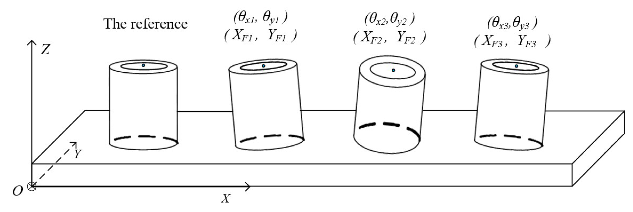
In order to identify the angle errors of machine tools, a high-accuracy angular standard should be provided by calibration. The workpiece coordinate system was established as shown in
Figure 5, and the relative angles
and
are the tilt angles of the plane mirror of the
th target around the
X-axis and
Y-axis, respectively. The first target was selected as the reference target, and the angle of the other targets were determined relative to it. The calibration relative angles could be obtained through measurement compensated by laser interferometer.
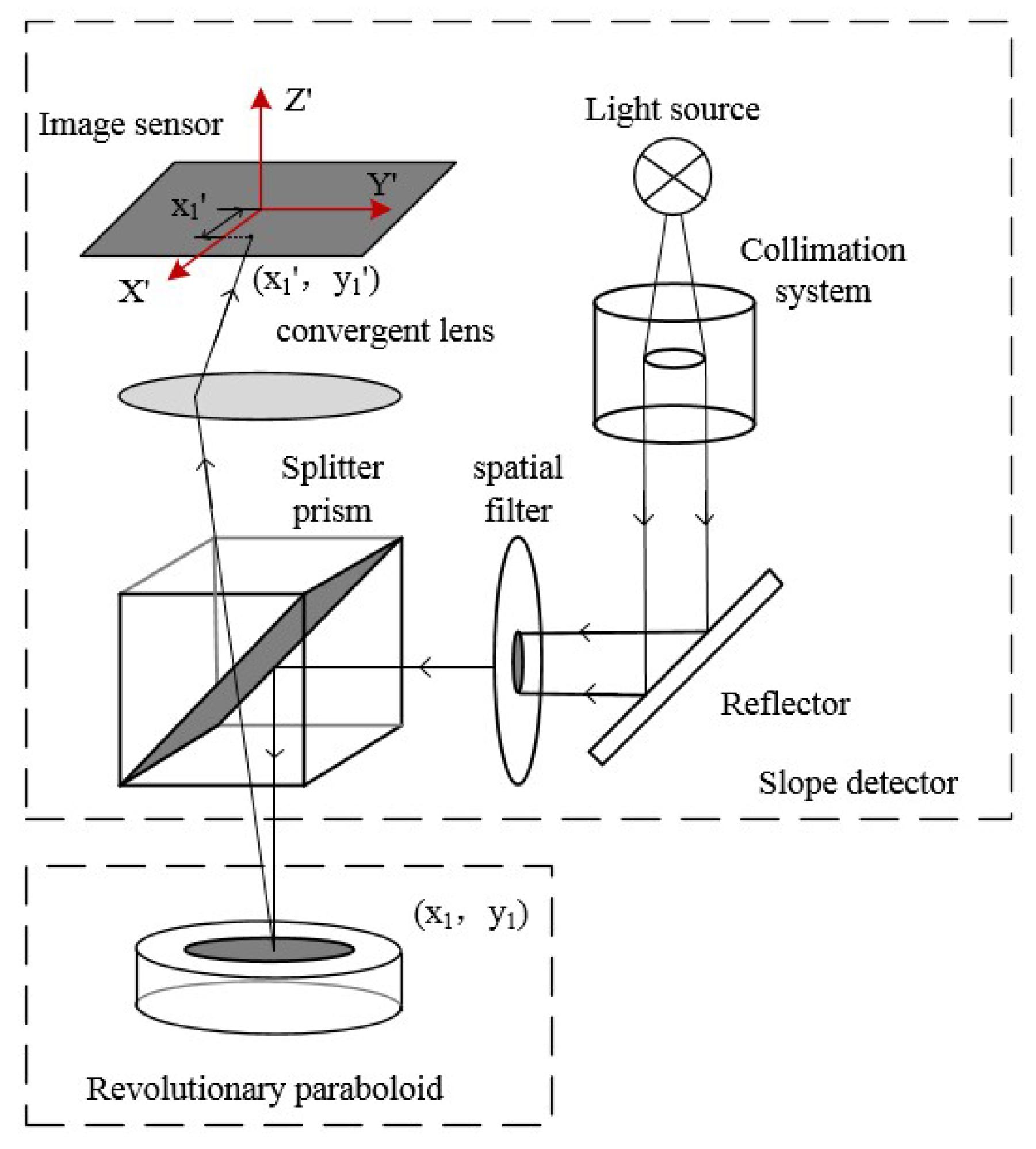
The spot displacement on the image sensor was proportional to the angle of the reflective surface, i.e., each pixel corresponds to 2.27 arc seconds. Subpixel spot extraction can improve the angle resolution by one order of magnitude. By using an angle sensor to measure every plane mirror, the displacement between the spot reflected by each plane mirror and that reflected by the reference plane mirror can be obtained. Due to the surface error of a plane mirror, it is rational to compute the average value of multiple samplings. As such, the calibration relative angles could be obtained through measurement compensated by a laser interferometer with an angular lens.
3.2. Calibration of the Relative Position
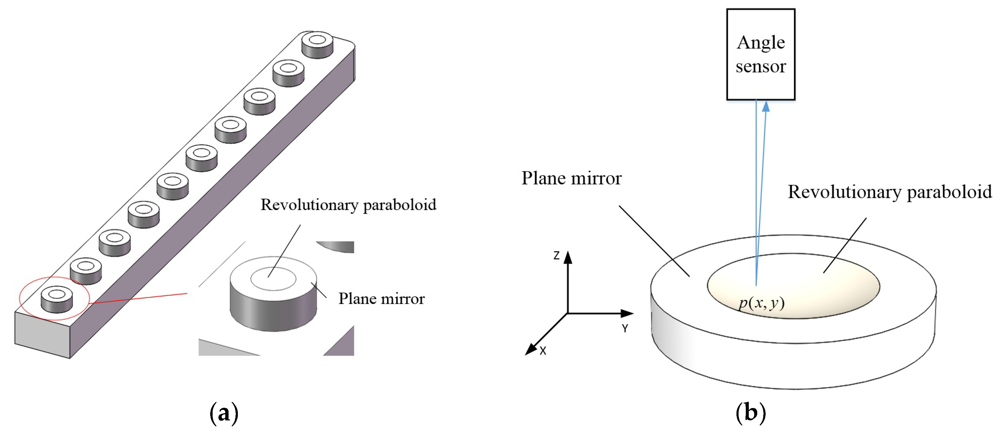
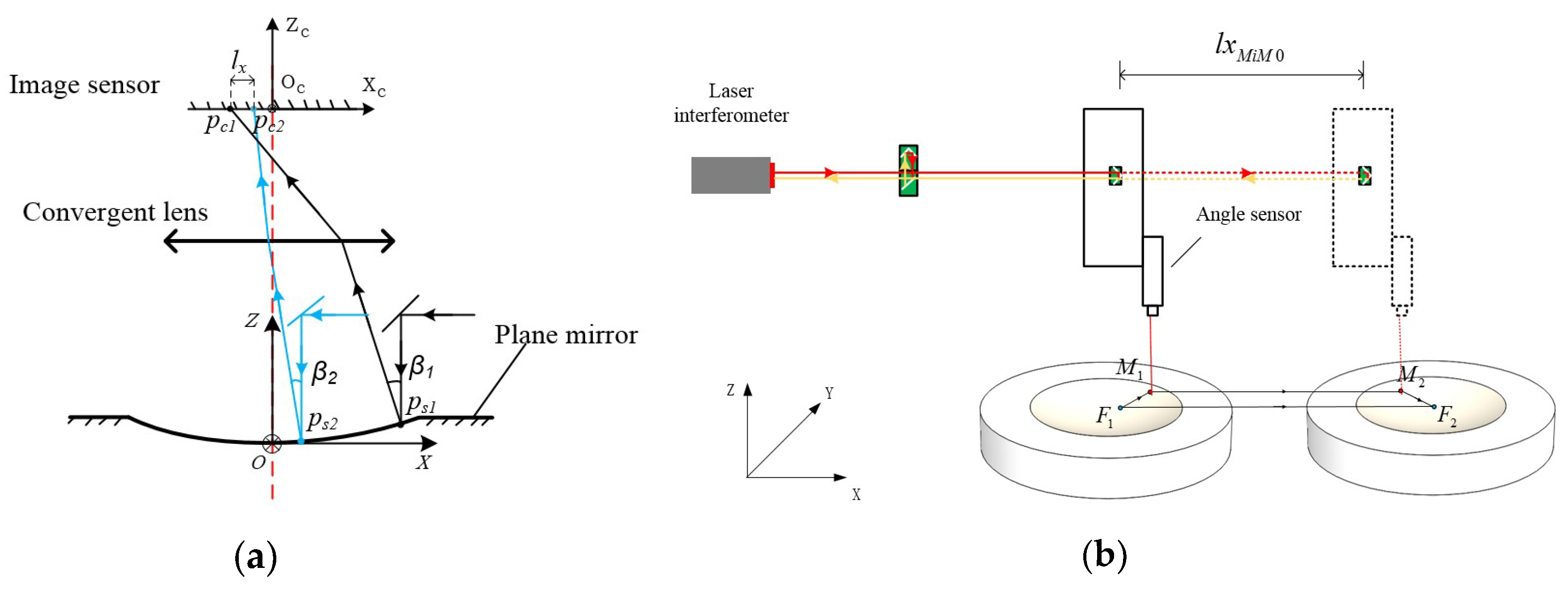
There is a point on every revolutionary paraboloid surface at which the tangent plane is parallel to the plane mirror around the revolutionary paraboloid. This point is defined as the feature point of the revolutionary paraboloid. To quantitatively determine the relative positioning of paraboloids, it can be defined as the relative positioning of the feature points of the corresponding paraboloids. Like the computation of the relative angle, the position of other targets was also found relative to the reference target, as shown in
Figure 5. The displacement values
are the relative position of the feature point of the
th target along the
X-axis and
Y-axis, respectively. As
Figure 6a shows, when the angle sensor moves along the
X-axis, the reflection point moves from
to
and the spot on the image sensor moves from
to
. In the same paraboloid, the translational displacement of the angle sensor, as mentioned above, is linearly related with the displacement of the spot on the image sensor. Besides this, the coefficient of linearity can be obtained by the measurement of the angle sensor on the revolutionary paraboloid. To conduct a large-scale measurement, the distances of the feature points of different revolutionary paraboloids should be determined.
In order to calculate the relative positioning of feature points in the workpiece coordinate system, the machine drives an angle sensor from the measurement point
to
along the
X-axis, as shown in
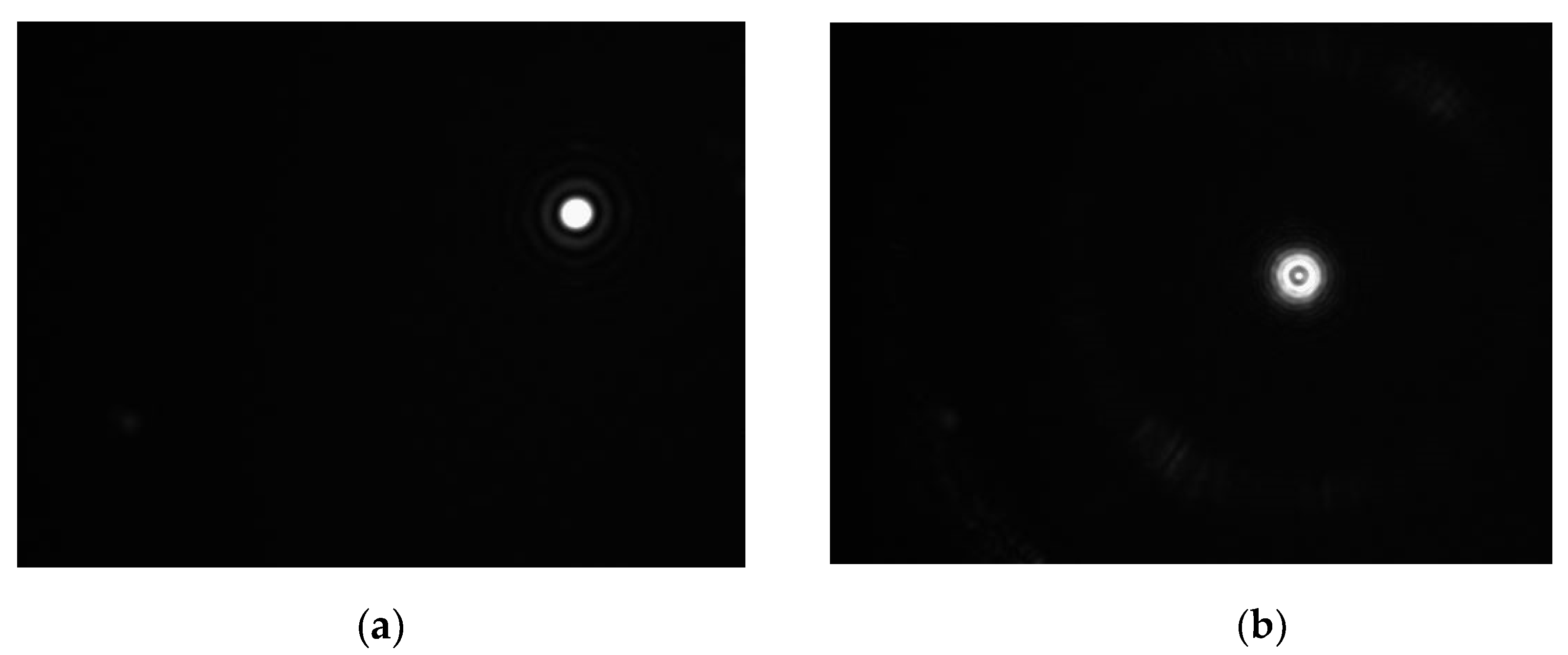
Figure 6b. The points
and
are defined as the feature points of two revolutionary paraboloids. Spot images of the feature point and the measurement point are shown in
Figure 7a,b. The position of the spot center is obtained by ellipse fitting, which can realize subpixel spot extraction. It was found by calibration that each pixel in the image corresponds to 2.27 arc seconds or 1.6
, and the resolutions of the angle and position can reach, respectively, 0.2 arc seconds and 0.16
by subpixel spot extraction. Actually, the spot image of a feature point cannot be obtained directly, so it is obtained by measuring the corresponding plane mirror.
As illustrated in
Figure 6b, the vector relation between two feature points
and
is described by the following equation:
In the
X direction, we have:
where
are the
X coordinates of feature points
in the object ordinate system, and
are the
X coordinates of measuring points
and
in the object ordinate system. Through measurement by laser interferometer with a position lens or machine tools with higher precision,
, defined as the distance between measuring points
and
, can be calculated. In addition, the distance between the measurement point and the feature point in a revolutionary paraboloid can be determined based on the spot displacement in an image by the following equation:
where
is the conversion coefficient from spot displacement to actual displacement calibrated by a laser interferometer;
are the
X coordinates of the measurement point and feature point of the
th revolutionary paraboloid in the object coordinate system; and
are the
X coordinates of the measurement point and feature point of the
th revolutionary paraboloid in the image system.
Since the aim of the computation of the relative positioning was to obtain the position of each feature point relative to the feature point of the reference revolutionary paraboloid, the
X coordinate
of the feature point of the reference revolutionary paraboloid was equal to 0. Therefore, in the
X direction, the relative position of the feature point of the
th revolutionary paraboloid can be calculated as follows:
Similarly, in the
Y direction, we have:
In these equations, and represent the relative position of the th feature point in the object system. Besides this, , , , , , and are the coordinates of the spot in the image system, and and are, respectively, the displacement in the X direction and the Y direction measured by laser interferometer or machine tools with higher precision.
3.3. Calculation of the 6 Degrees-of-Freedom Errors
By the method mentioned in
Section 3.1 and
Section 3.2, the relative angles
and position
and
of the
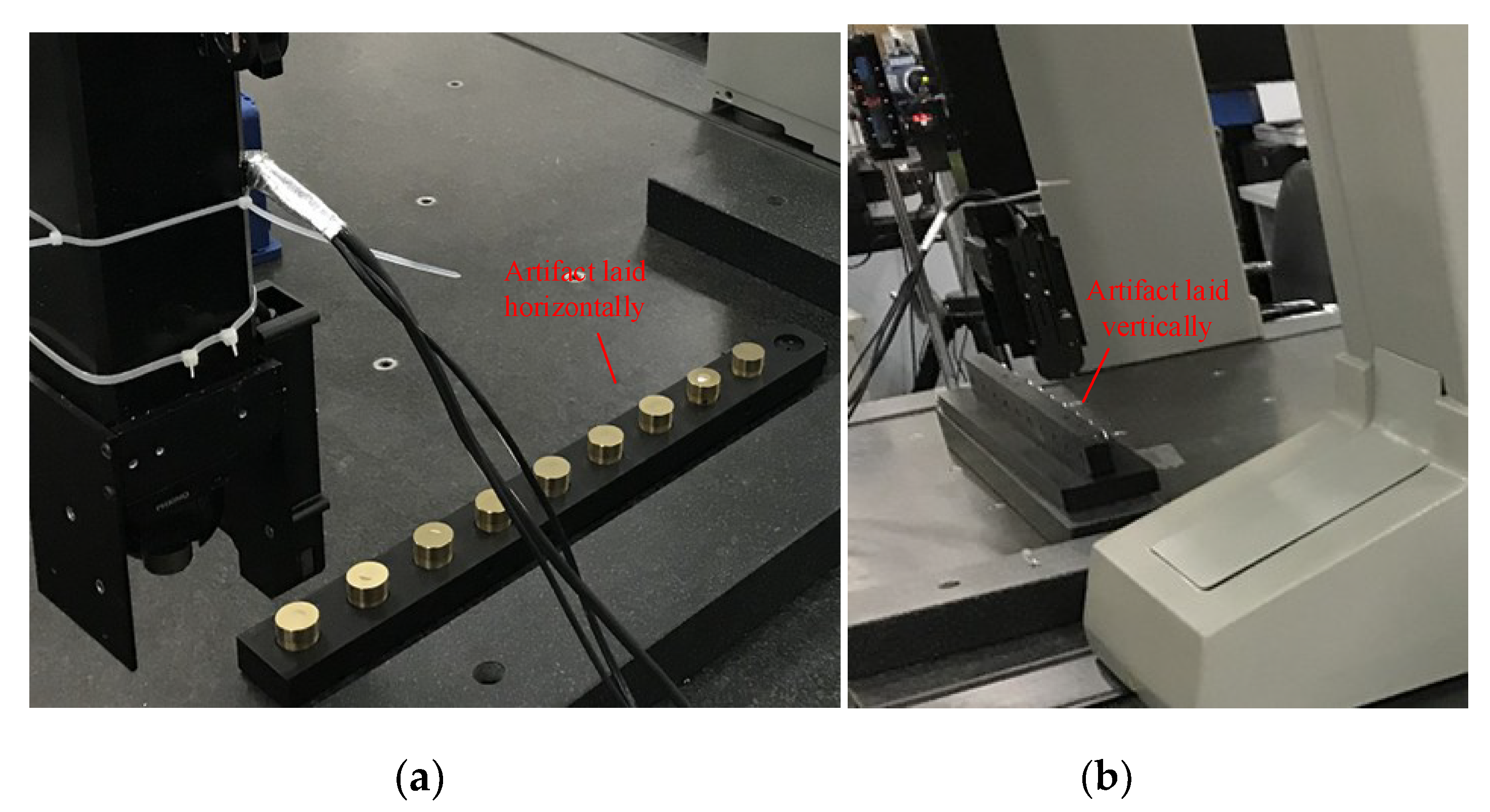
th target were calibrated. To ensure repeatability of the measurement system, the angle difference between the first and the last plane mirror should be, where possible, the same as the angle difference of calibration. The alignment can be conducted based on the spot position in the image, which can reduce the cosine error of the measurement effectively. When the 1-D artifact was located on the
X-axis of the machine tool horizontally, the measurement value of the relative angles
and relative position
and
of the
th target could be obtained by the machine tool to be tested. In the process of measurement,
and
should be computed by the feedback value of the machine tool. That means that
,
are obtained by the following equations:
where
,
,
,
,
,
, and
are the coordinates of the spot in the image system when measuring horizontally, and
,
,
, and
are the measured coordinates of the measurement point in the machine coordinate system.
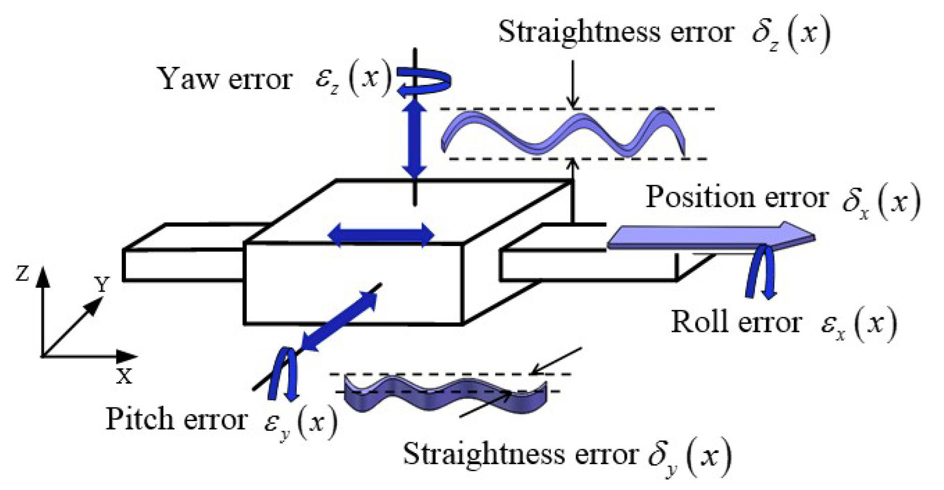
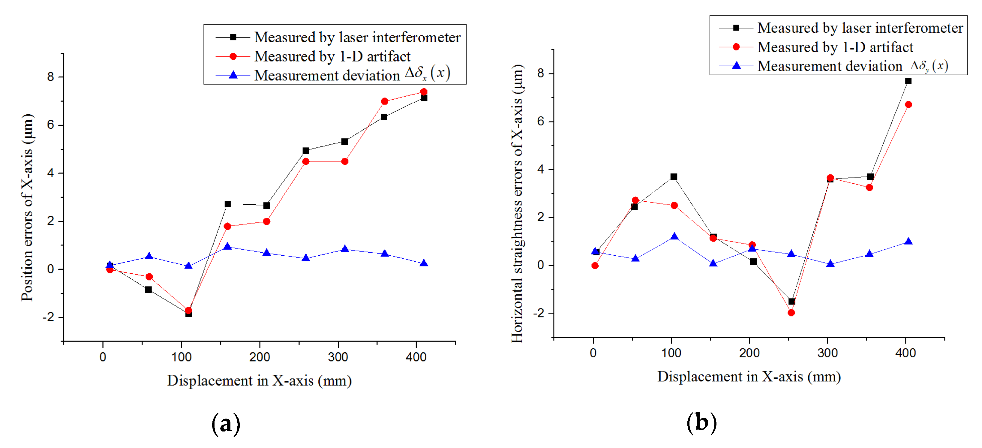
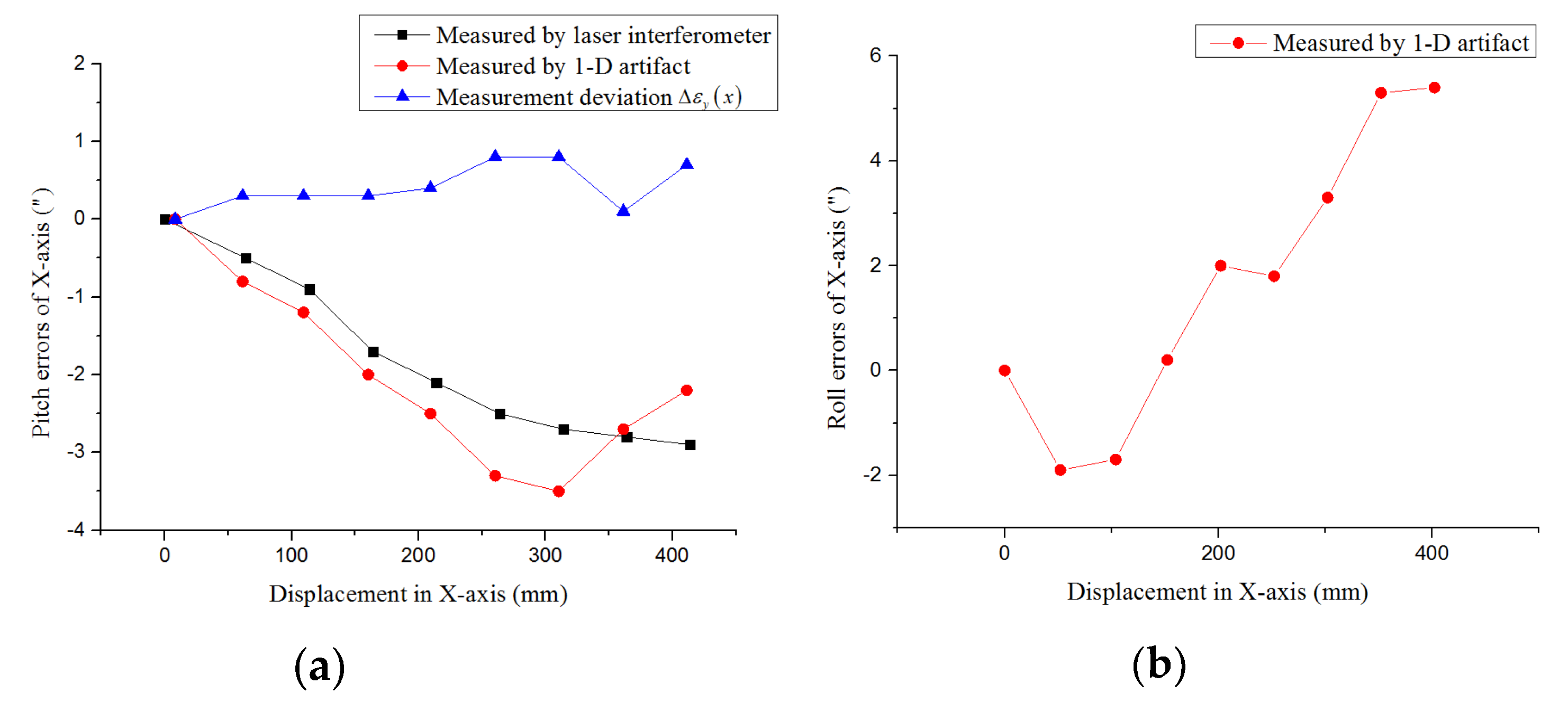
Due to geometric errors in the linear motion of the machine tool, the relative angle and position measured by the machine tool are not the same as the calibration values. The roll error and pitch error are caused by deviation in the relative angles and the position error and horizontal straightness error are caused by deviation in the relative position. Thus, by calculating the deviation between the measurement values and calibration values, these errors at the target positions can be identified.
The roll error
and the pitch error
at the target position can be identified by the following equations:
Due to the character of a revolutionary paraboloid, the displacement difference measured by the machine tool includes coupling of angle errors. Hence, the position error
at the target position can be identified by the following equation:
where
and
represent the conversion coefficients from spot displacement in the image to actual displacement and from angle variation to spot displacement in the image, respectively, and
is the pitch error at the target position.
Similarly, the horizontal straightness error
can be identified by the following equation:
When the 1-D artifact is located vertically, the measurement values of the relative angles
and
and relative position
and
of the
th target can be obtained by the following equations:
where
,
,
,
,
,
, and
are the coordinates of the spot in the image system when measuring vertically. Unlike horizontal layouts, the
Y coordinates of each target are calculated based on the displacement in the
Z direction of the machine. Thus, the
X coordinates
and the
Z coordinates
of the measurement point in the machine coordinate system were used to compute the relative positions of targets.
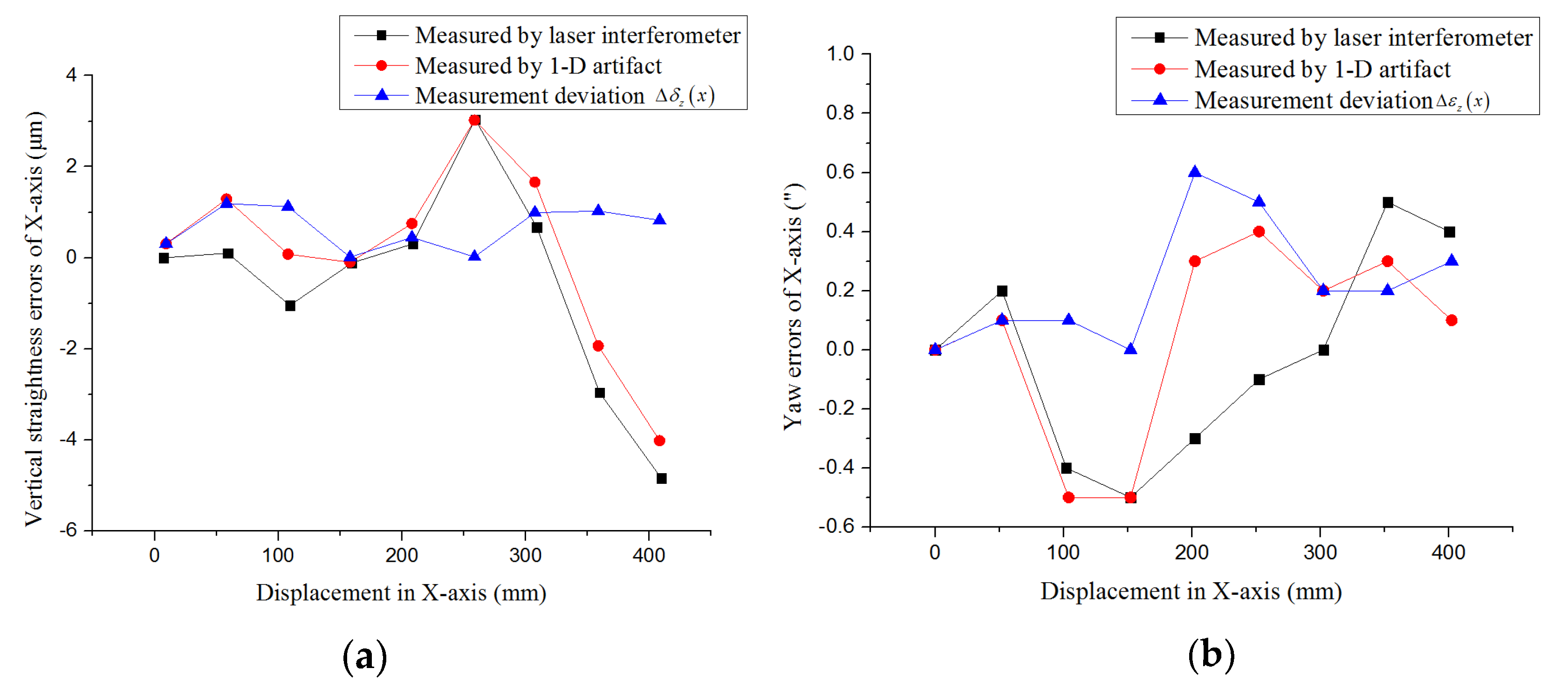
Similarly, the yaw error
and the vertical straightness error
, instead of the pitch error
and horizontal straightness error
, are caused by deviation in the relative angle
and position
. Therefore, the yaw error
can be identified by the equation:
and the vertical straightness error
can be identified by the equation:
Thus, the 6 degrees-of-freedom errors of a linear motion guide rail can all be identified.

 ,
, 


