Article

Deformation Behavior of Transient Liquid-Phase Sintered Cu-Solder-Resin Microstructure for Die-Attach

1
Manufacturing Engineering Center, Mitsubishi Electric Corporation, Hyogo 6618661, Japan
2
Division of Materials and Manufacturing Science, Graduate School of Engineering, Osaka University, Osaka 5650871, Japan
*
Author to whom correspondence should be addressed.
Appl. Sci. 2019, 9(17), 3476; https://doi.org/10.3390/app9173476
Submission received: 29 July 2019 / Revised: 16 August 2019 / Accepted: 20 August 2019 / Published: 23 August 2019
(This article belongs to the Special Issue Nanotechnology for Novel Nanojoining and Microjoining)

Abstract

:
We have proposed a low-temperature bonding technology utilizing the sintering of Cu particles with transient liquid-phase of Sn-based solder, called transient liquid-phase sintering (TLPS), as a die-attach solution for high-temperature power modules. A copper-intermetallic compound-resin (Cu-IMC-resin) microstructure, which consists of Cu particles connected with Cu–Sn intermetallic compounds (IMCs) partially filled with polyimide resin, is obtained by the pressureless TLPS process at 250 °C for 1 min using a novel Cu-solder-resin composite as the bonding material in a nitrogen atmosphere. Macro- and micro-deformation properties of the unique microstructure of the TLPS Cu-IMC-resin are evaluated by finite element analysis using a three-dimensional image reconstruction model. The macroscopic computational uniaxial tensile tests of the Cu-IMC-resin model reveal that the utilization of the IMCs and the addition of the easily-deformable resin facilitates the temperature-stability and low-stiffness of the mechanical properties. The microstructure exhibits a significantly low homogenized Young’s modulus (11 GPa). Microscopic investigations show that the local stresses are broadly distributed on the IMC regions under uniaxial macroscopic tensile displacement, indicating highly reliable performance of the joint within a specific macroscopic strain condition. Numerical and experimental investigations demonstrate the excellent thermal cyclic reliability of die-attached joints between silicon carbide chips and directly bonded copper substrate.

1. Introduction

The rapid advancement of hybrid electric vehicles (HEVs) and other power electronic systems has increased the demand of highly reliable bonding technologies in the power modules. The operation of power modules at high powers and frequencies, along with high integrability and miniaturization capability is highly desired [1]. Moreover, the utilization of next-generation semiconductor material; silicon carbide (SiC), instead of the conventional materials offers lower power loss, higher switching speed, and higher operating temperature, which has recently exceeded 175 °C and even reached 200 °C [2]. As the bonding layers are also exposed to such high temperatures, the performance metrics and reliability of joints should be improved. Sn-based soldering is conventionally used in die-attach applications; however, the maximum operating temperature is limited to lower than 175 °C in Sn-Ag-Cu solders. Therefore, alternative bonding technologies with higher heat tolerance are in great demand. Silver sinter bonding technologies are representative technologies for next-generation power modules, which have been reported to provide outstanding thermal and electrical conductivity and highly reliable performance [3,4,5,6,7,8,9]. Although the traditional sintering process requires complicated pressure-assistance, optimized bonding materials for pressureless bonding have recently emerged as powerful alternatives [10,11,12,13]. However, high-cost and low compatibility with conventional soldering processes inhibit the industrial use of these materials. Another low-cost bonding method, copper sinter bonding, has been researched, as it provides excellent conductivity, high-temperature durability and high electrical migration resistance [14,15,16]; however, surface coating of Cu particles or reducing the atmosphere for the sintering process was generally required because of its oxidation affinity under storage in air, which inhibits sintering. Thus, inexpensive and highly reliable bonding technologies are being investigated for advanced power modules.
Recently, low-temperature bonding utilizing the sintering of Cu particles with the transient liquid-phase of Sn-based solder, called Cu-Sn transient liquid-phase sintering (TLPS), has been proposed as a low-cost technology for high temperature electronic applications [17]. Once the solder is completely transformed into a Cu-Sn intermetallic compound (IMC) during the reflow process, a bonding layer with high re-melting temperature can be obtained. Several studies have demonstrated the high bondability and high-temperature resistance of the Cu-Sn system [18,19,20,21] and similar Ni-Sn and Ag-Sn systems [22,23,24]. These studies focused on the realization of “dense” IMC bonding layer and high joint strength using a low-temperature and short-time bonding process based on interdiffusion control between the metal particles. The “dense” IMC joints might exhibit high strength at elevated temperatures; however, it has been reported that the stiffness and brittleness of the IMCs cause strength reduction or joint fracture through thermal cyclic operations [25,26,27,28,29].
Further, the addition of resin into TLPS layer has been extensively investigated in the field of electronic packaging. For example, Shearer et al. [30] reported that the TLPS polymer adhesives exhibit a stable electrical connection and can be used as a laminate-based microvia to interconnect electronic devices. Gallagher [31] also demonstrated the feasibility of the TLPS conductive adhesives for surface mount technology (SMT). Moreover, underfilled mold resins are widely used as reinforcement of solder bumps for highly integrated electronic packaging [32]. These resins are usually expected to show relatively rigid mechanical properties to reinforce “metallic” joints. Therefore, deterioration of resins, which includes delamination, decomposition, void formation, etc., are vital issues for these resins. Thermal stress within the metal-resin composite joint is an additional serious concern because the coefficient of thermal expansion (CTE) of most resins is much higher than that of the metal part. In contrast, the addition of a “soft” resin with quite low Young’s modulus and yield strength is a promising approach for reducing the joint stiffness to facilitate the utilization of TLPS technique in high-temperature power modules.
We have proposed an approach for the stiffness reduction of TLPS joints using a novel Cu-solder-resin composite for die-attach applications. We have already proven the feasibility of this approach [33] and demonstrated excellent thermal stability during thermal storage test at 200 °C for 1000 h [34]. The TLPS joint was composed of stiff Cu–Sn IMCs, ductile Cu, and soft resin, which were expected to reduce the apparent stiffness of the joint. The added resin plays the role of a “spacer,” enabling the formation of an inherent skeleton-shaped microstructure composed of Cu and IMCs. In this study, a unique microstructure of the TLPS joint is proposed and finite element (FE) analysis based on three-dimensional (3D) image reconstruction is used to elucidate the macro- and micro-deformation properties of the microstructure. The macroscopic mechanical properties of the TLPS microstructure are estimated through computational tensile tests, where the constituents are considered as homogenized materials. The mechanical properties of the materials and the ambient temperature are varied to clarify their effect on the stability of the joint. Structural FE simulations mimicking thermal cycling tests of SiC-die-attached specimens are used to predict their reliability by using the calculated homogenized mechanical properties of the microstructure, which are compared with those obtained by experimental thermal cycling results. Finally, the deformation behavior of the microstructure is investigated to identify crack initiation sites microscopically.

2. Experimental Method

The Cu-solder-resin composite was a paste containing Cu particles, Sn–3Ag–0.5Cu (SAC305) solder particles, and polyimide (PI) thermosetting resin. The melting point of the solder was 220 °C. The cure temperature of the PI resin was 230–240 °C. The size of the Cu particles and solder particles were approximately 10 and 3 μm, respectively. The content of the copper in wt.% was approximately three times higher than that of the solder, which facilitated the consumption of the solder through the formation of Cu–Sn IMCs. The PI resin was chosen by considering the curing temperature close to the melting point of the solder and soft mechanical properties, with a yield strength of approximately 1 MPa. This enabled the easy deformation of the resin when it was embedded in the microstructure of Cu and IMCs. The decomposition temperature of the polyimide was greater than 400 °C. SiC chips were bonded to direct bonded copper (DBC) substrates using the Cu-solder-resin composite. The chips had approximate dimensions of 8 × 8 × 0.3 mm and a Ni/Au surface metallization. The DBC substrates were composed of two 0.3-mm-thick copper electrodes bonded to a 0.6-mm-thick silicon nitride (Si3N4) substrate. The joints were bonded at 250 °C for 1 min after preheating at 100 °C for 60 min using the pressureless reflow process in a nitrogen atmosphere. A unique skeleton-shaped Cu-IMC-resin microstructure was generated by heating the resin composite up to the reflow temperature. Further details about the process, materials, and geometries can be found in our previous report [33].
The SiC-DBC joint was molded by cross-sectioning resin. The serial cross-sectional images of the bonding layer were then obtained by focused-ion-beam scanning electron microscopy (FIB-SEM; NX2000, Hitachi High-Technologies Corporation, Tokyo, Japan) to investigate the three-dimensional (3D) microstructure. The approximate central region of the bonding layer was visualized, where the size of the field of view (FOV) and pitch of the cross-sectional slices were 50 × 50 μm and 0.5 μm, respectively. We obtained 100 cross-sectional images, which were used for 3D reconstruction of the microstructure by FE modeling as described in the next section.
The SiC-DBC joints were subjected to thermal cycling tests using a thermal cycling chamber (TSA-73EH, ESPEC Corporation, Osaka, Japan) in the temperature range from −55 to 175 °C with a dwell time of 15 min at both minimum and maximum temperatures. Similar tests were performed on the SiC-DBC joints bonded by a commercial SAC305 solder paste for comparison. Six joints of each type were tested. Non-destructive observations of the die-attached layers were performed every 300 thermal cycles using scanning acoustic tomography (SAT; FineSAT III, Hitachi Power Solutions Co. Ltd., Ibaraki, Japan). The resolution of the SAT was 0.1 mm × 0.1 mm. The ratio of unbonded areas was obtained by binarizing the SAT images using an image editing software. After thermal cycling tests, a representative joint was selected from the six joints, and cross-sections along the diagonal axis of the joints were visualized by field-emission scanning electron microscopy (FE-SEM; SU8000, Hitachi High-Technologies Corporation).

3. Finite Element Analysis

3.1. Modeling of the Cu-IMC-Resin Microstructure Based on 3D Image Reconstruction

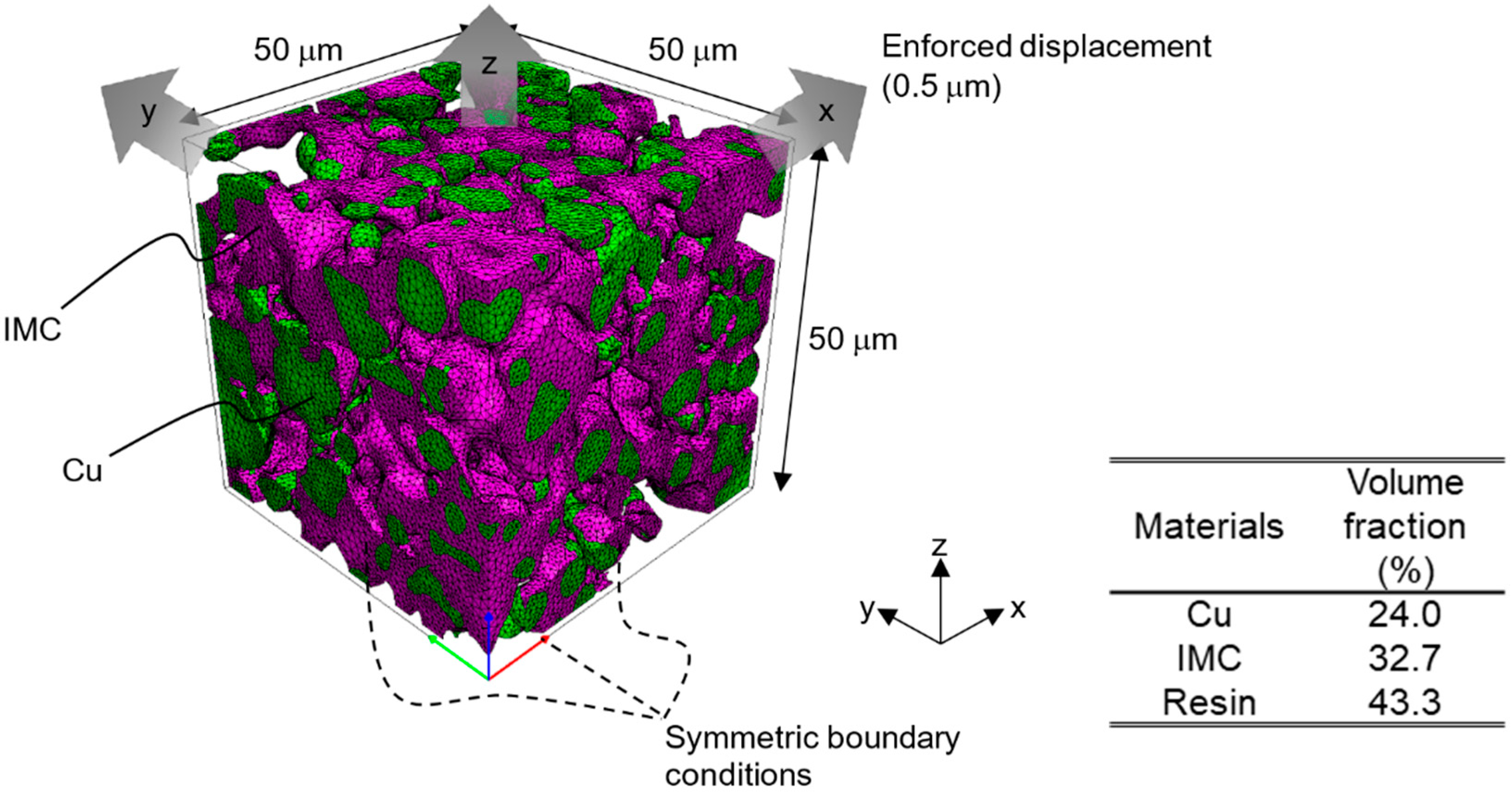
3D image reconstruction of the serial cross-sectional SEM images provided useful insights about the mechanical properties of the Cu-IMC-resin microstructure. Figure 1 shows the segmentation flow of these images. The resolution of the original SEM images was 0.06 μm/pixel. These images were segmented into three regions, which were Cu, IMCs, and PI resin, based on their brightness using a commercial image processing software, Amira, as shown in Figure 1b,c. The subsequent steps were performed by an image processing and meshing software, Scan IP, Simpleware. These steps included resizing of the images into the resolution of 0.5 μm/pixel and Gaussian smoothing, as shown in Figure 1d. The latter was done to reduce the number of FE mesh cells. Finally, the images were resegmentated to remove the tiny cavities and islands, whose sizes were approximately less than 1 μm, as shown in Figure 1e. Figure 2 and Figure 3 show the reconstructed cubic 3D model with sizes of 15 and 50 μm, respectively. These models were composed of quadratic hexahedral elements, where the number of nodes and elements in the 15- and 50-μm-sized model were 118,305 and 65,919, and 1,535,038 and 833,105, respectively. The volume fractions of Cu, IMC, and PI resin in the latter model were 24.0, 32.7, and 43.3%, respectively.
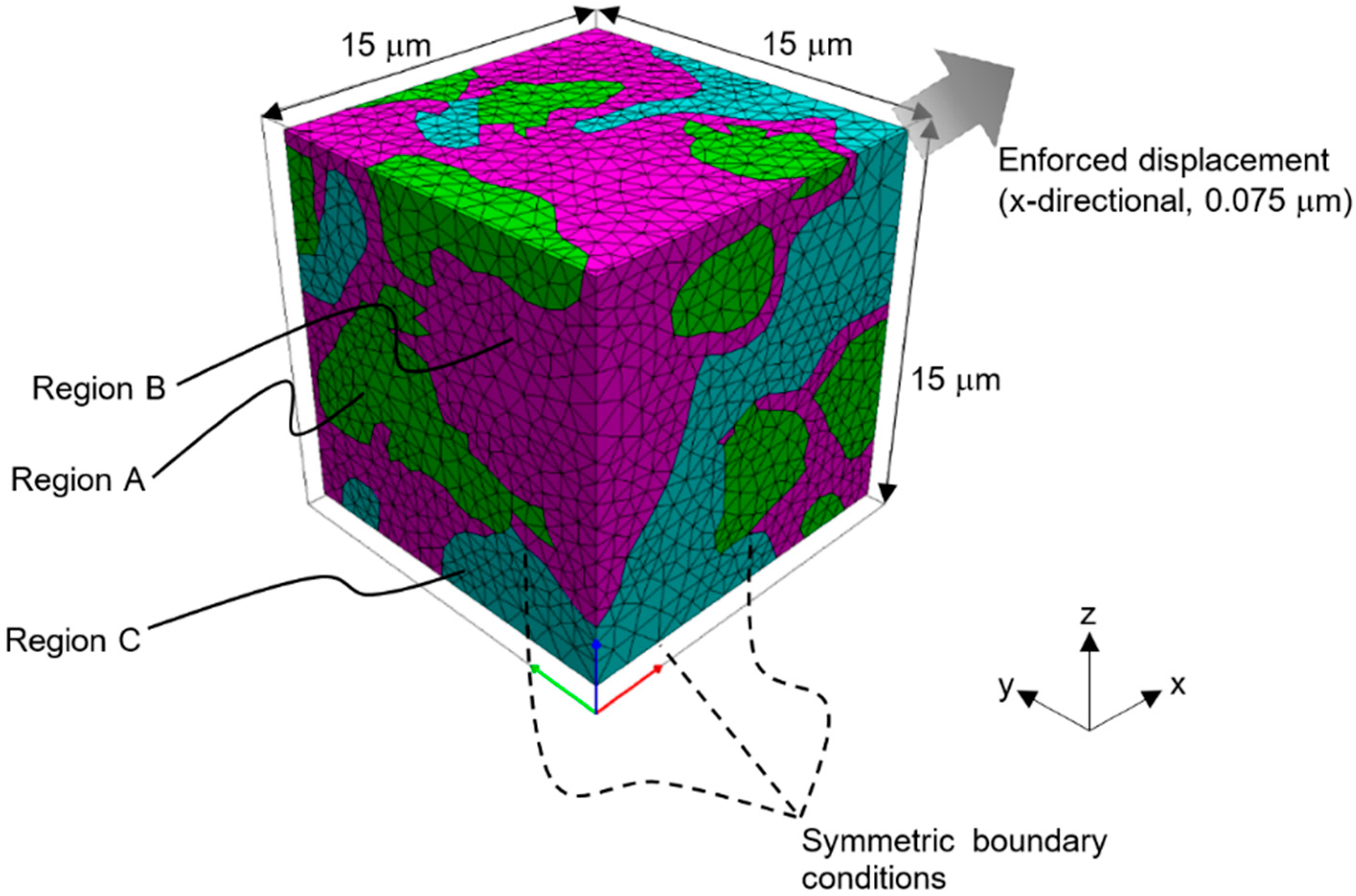
Mechanical FE simulations were performed to estimate the macro- and micro-deformation properties of the microstructure using the commercial software, ANSYS Workbench 18.2 [35]. The 15-μm-sized model (Figure 2) was used to predict the effect of IMC and resin on the homogenized mechanical properties. The model was divided into regions A, B, and C, which represented the presence of Cu, IMC, and resin, respectively. The 1/8 model was used for FE analysis considering the symmetry conditions. Ideal contact was assumed between all the interfaces. An external displacement of 0.075 μm along the x-axis, equivalent to the macroscopic strain of 0.5%, was applied to the yz-surface of the FE model. Ambient temperatures of −55, 22, 100, and 175 °C were considered in the simulations. The homogenized nominal stress-stain curves of the microstructure were calculated at each temperature from the displacement u and the averaged reaction force F on the surface subjected to external displacement, using the following expressions:
σ = F L 2 ,
ε = u L ,
where L is the size of the cubic model. The homogenized Young’s modulus and the yield strength were obtained from these curves.
A parameter study was performed based on the cases shown in Table 1, where the effects of materials properties in the regions B (IMC) and C (resin) on the microstructure were validated. The properties of PI resin were obtained using tensile tests of the cured PI resin film, and that of the epoxy resin (reference) were acquired from its commercial specifications. Further, air instead of resins was considered as the region C in the cases for comparison to clarify the effect of the mechanical properties of resins on the microstructure. Furthermore, the cases with SAC305 instead of IMC as the region B were examined to clarify the effect of the mechanical properties of IMC on the microstructure. The relevant parameters of the materials are summarized in Table 2 and Table 3 [36,37,38,39,40,41]. Cu, SAC305, and resins were considered as multi-linear elastoplastic materials with the isotropic hardening described as follows:
σ = { E ε ( 0 ε ε Y ) σ UTS σ Y ε UTS ε Y · ( ε ε Y ) + σ Y ( ε Y < ε ε UTS ) σ UTS ( ε > ε UTS ) ,
In contrast, all the other materials were modeled as linear elastic. The mechanical properties of Cu, SAC305, and PI resin were considered to be temperature dependent.
The utilization of 15-μm-sized model for the analysis provided a quick and efficient prediction of the effect of IMC and resin on the homogenized mechanical properties, whereas that of the 50-μm-sized model provided detailed information about these properties. For the latter, symmetry conditions, ideal contact between all interfaces, and ambient temperature were considered similar to the former method. An external displacement of 0.5 μm along the x, y, and z axes, which is equivalent to the macroscopic strain of 1%, was applied to the yz-, zx-, and xy-surfaces for uniaxial tensile test, respectively. The homogenized properties of the Cu-IMC-resin microstructure, i.e., nominal stress-strain relations, Young’s modulus, and yield strength, at each temperature were calculated using the similar approach described earlier. Moreover, the homogenized Poisson’s ratio was calculated from the average displacement of each edge surface of the cubic model against the external load, and the homogenized CTE was calculated from the average displacement while the temperature changed from 22 to 30 °C.

3.2. SiC-DBC Model Based on Homogenized Properties of Cu-IMC-Resin

A 3D FE model was set up using ANSYS Workbench 18.2, which is shown in Figure 4. It consists of a bonding layer sandwiched between a SiC chip and DBC substrate. Homogenized mechanical properties estimated from the Cu-IMC-resin model based on 3D image reconstruction were used. These properties were considered as the average of the calculated results for loading along x-, y-, and z-axis directions. The other material properties are listed in Table 2. Dimensions of 8 × 8 × 0.3 mm, 8 × 8 × 0.07 mm, 12 × 12 × 0.3 mm, and 12 × 12 × 0.6 mm were chosen for the SiC chip, bonding layer (Cu-IMC-resin, IMC (Cu6Sn5), or SAC305), Cu electrode, and Si3N4 substrate, respectively. Here, the 1/4 model was used for FE analysis considering the symmetry conditions. Quadratic hexahedral elements were used, where the number of nodes and elements in the model were 105,299 and 22,300, respectively. Macroscopic strain, which was used for the microscopic simulations to locally identify the crack initiation sites in the model, was calculated for ten steady-state cycles in which the temperature oscillated between −55 and 175 °C. Thermal stress and strain were generated due to the CTE mismatch of the constituent materials during the temperature variation.

4. Results and Discussion

4.1. Characterization of Macro-Deformation Behavior

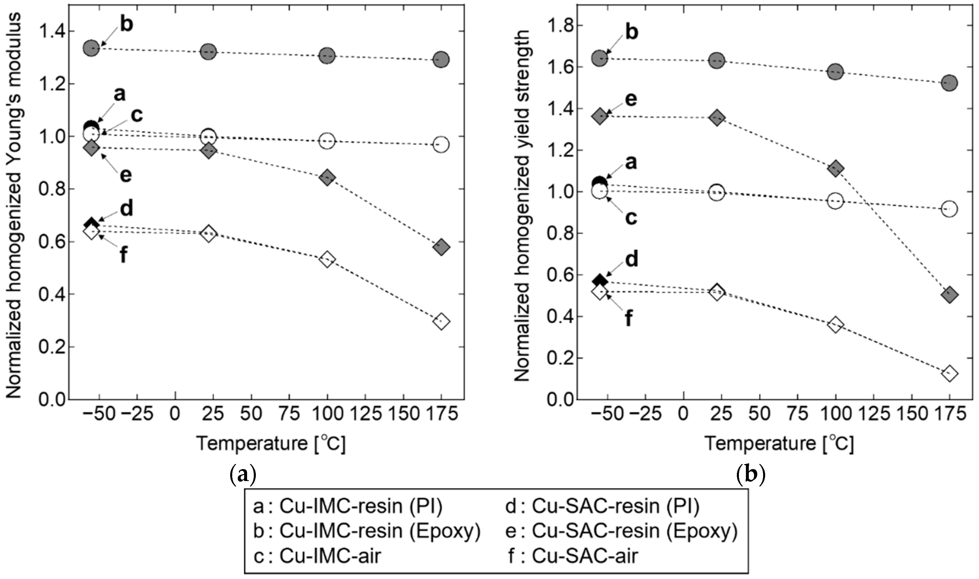
Figure 5 shows the homogenized Young’s modulus and yield strength calculated at each temperature using the 15-μm-sized models of Cu-IMC-resin and Cu-SAC-resin, where the resin region is PI, epoxy, or air; the values are normalized with respect to that of the Cu-IMC-resin at 22 °C. The normalized homogenized Young’s modulus of the Cu-IMC-resin is stable against temperature, whereas that of the Cu-SAC-resin decreases with the increase of temperature. The yield strength shows a similar trend (Figure 5b). These trends indicate the stability of properties in Cu and IMC against temperature variations as compared to SAC. In addition, the Young’s modulus and yield strength in the models with PI resin and air exhibit a minor difference. Thus, these FE results suggest that the IMC inhibits “softening” at high temperatures accompanied by a reduction in the Young’s modulus and yield strength, which is a significant advantage over SAC solder. Moreover, the load-bearing capacity of PI resin is very small due to its softness.
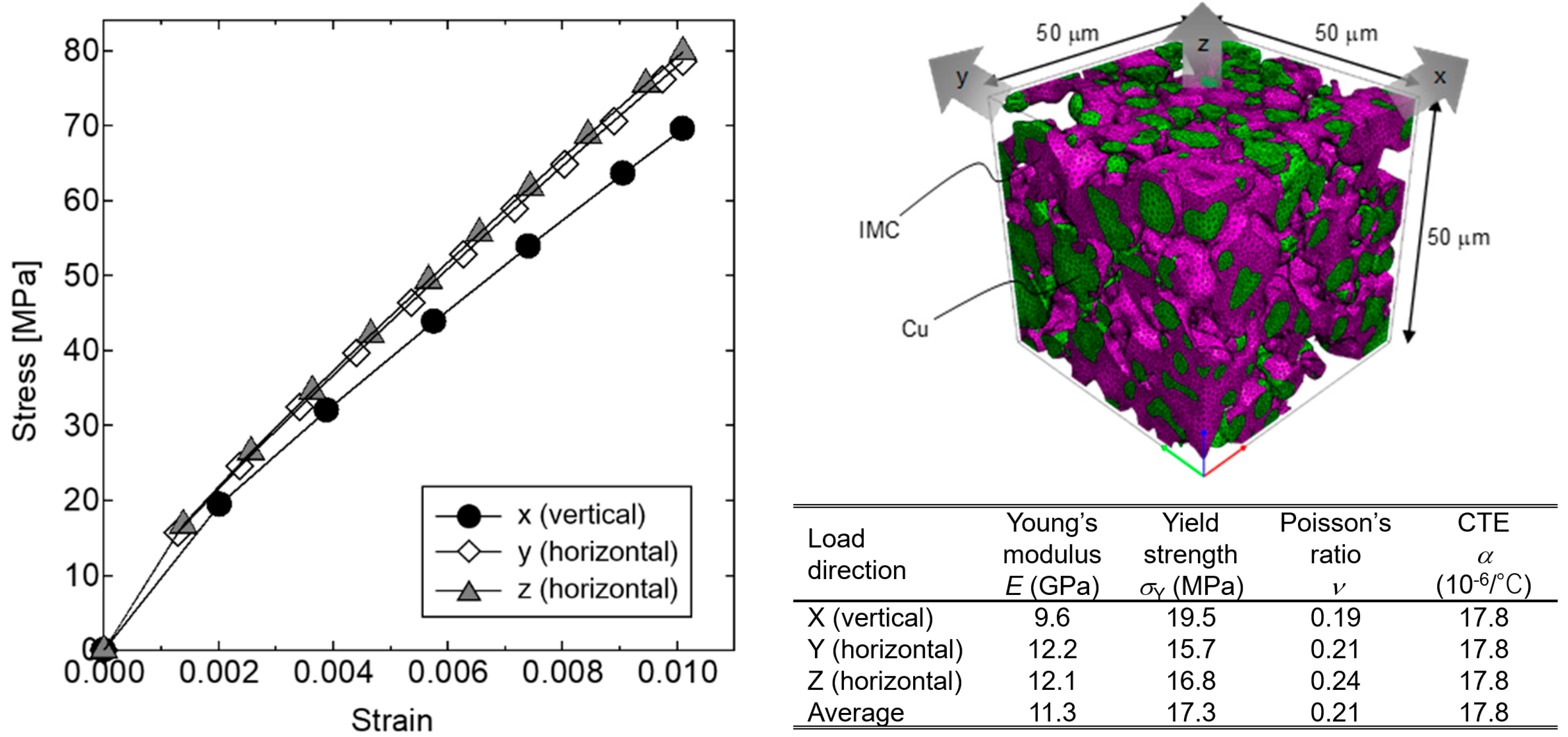
Figure 6 shows the homogenized nominal strain–stress curves and mechanical properties calculated with the 50-μm-sized model. Here, the PI resin part is treated as air for reducing the calculation elements of the model based on the results shown in Figure 5. Although the IMC is considered as a linear elastic material, the curves show a deformation behavior with a yield point. The Cu-IMC-resin microstructure exhibits isotropicity, i.e., there is a negligible difference between the obtained properties along the three load-directions. The Young’s modulus of the Cu-IMC-resin composite (11.3 GPa) is significantly smaller than that of IMC (Cu6Sn5, 102 GPa). Moreover, the modulus of the Cu-IMC-resin microstructure is 1/4 times smaller than that of the solder (SAC305, 46 GPa) also. This implies that the Cu-IMC-resin microstructure shows significantly low stiffness compared to the IMC and solder. In addition, CTE is 17.8 × 10⁻⁶/°C. The temperature dependence of the homogenized yield strengths was also evaluated using the same method as described before at various ambient temperatures from −55 to 175 °C. The calculated yield strengths at −55, 22, 100, and 175 °C are 17.4 (+0.6%), 17.3 (reference), 17.0 (−1.9%), and 16.7 MPa (−3.7%), respectively. For comparison, those of the SAC305 solder at 22, 100, and 200 °C are 45 (reference), 15 (−66.7%), and 3 MPa (−93.3%), respectively [40,41]. These results confirm that the Cu-IMC-resin microstructure exhibits remarkably stable mechanical characteristics against temperature variation.

4.2. Reliability of TLPS Joints during Thermal Cycling

Figure 7 shows the relationship between the number of temperature cycles and the ratio of unbonded areas of SiC-DBC joints of TLPS and SAC305 obtained from the SAT images. The SAT images of the joints after thermal cycles can be found in our previous work [33]. The size of the detected unbonded regions is larger than 0.1 mm × 0.1 mm, which is the resolution of the SAT equipment used in this study. The ratio of the unbonded areas of the SAC305 joints increases to 6%, while that of the TLPS shows a minor increase after 1200 thermal cycles. Figure 8 shows the cross-sectional SEM images of the TLPS and SAC305 joints after thermal cycles, which displays crack-like connected cavities in the SAC305 joints and no apparent deterioration in the TLPS joints. These observations confirm that the TLPS joints are more reliable than the SAC305 solder joints, i.e., the former exhibits fewer crucial delamination or cracks, which are less likely to affect the heat dissipation.
Figure 9 shows the FE simulation results of the thermal cycling tests for the SiC-DBC joint bonded by the TLPS layer, where the homogenized properties based on 3D image reconstruction are used. The joints exhibit strain peaks at the edges and corners of the bonding layer, where cracks were expected. The homogenized TLPS joint shows the maximum strain ~ 0.4%, which was generated during the thermal cycle with minimum temperature. In contrast, quite low Mises stress was generated in the TLPS layer as compared to that in the DBC substrate. In addition, no stress concentration on the DBC substrate was identified. The relationships between the number of thermal cycles and the calculated Mises strain and stress are shown in Figure 10a,b, respectively. Remarkably, the Mises strain of the homogenized TLPS joint did not increase through the cycles, while that of the SAC305 joint increased in every cycle. Further, the normalized Mises stress of the homogenized TLPS joint (0.08, −92%) is low compared to that of IMC (1.00, reference) and SAC305 (0.11, −89%). These results suggest that the TLPS facilitates the reduction of the both Mises strain and stress macroscopically through thermal cycling.
In an earlier study [34], we demonstrated the excellent thermal reliability of the TLPS joints after thermal aging at 200 °C for 1000 h through temperature storage tests, where IMC of the microstructure transformed from Cu6Sn5 to Cu3Sn along with the formation of submicron voids at the interface between Cu and IMCs during the thermal aging. The IMC was treated as the Cu6Sn5 in the simulations. Although, Cu3Sn generally exhibits superior properties: higher strength, higher elongation, and lower elastic modulus compared to Cu6Sn5 [18,42], the transformation of the IMCs and formation of the submicron voids needs to be explained, which will be discussed in future work. The results of FE analysis in this study suggested the stable mechanical properties of the IMC-based composites at high temperature, which is a significant advantage of these composites over the solder-based ones. Furthermore, although the reinforcement of solder-based joint by mold resin is generally effective, the reinforcement of IMC-based joint is not required because of its temperature-stable characteristics. The temperature-stable mechanical properties of the IMC enable the utilization of a soft resin as a part of the composite microstructure; in other words, significant stiffness reduction could be achieved by utilizing the resin with soft material properties and the temperature-stable IMC.

4.3. Impact of the Macro- and Micro-Deformation Behavior on the Thermal Cycling Reliability

The macroscopic deformation behavior of the model through thermal cycling is shown in Figure 10, where the strain of the TLPS joint is not increased in each subsequent thermal cycle (Figure 10a). This FE simulation result suggests that the TLPS joint deforms macroscopically during the elastic deformation stage. The joint lifetime of elastoplastic materials can be estimated by the following Coffin–Manson equation:
N f = C · ε ie n ,
where Nf is the number of cycles till failure, ∆εie is the increase in strain per cycle, and C and n are the material-dependent lifetime coefficient and exponent, respectively. The macroscopic strain amplitude of the TLPS joint is shown in Figure 10a, where ∆εie ~ 0, which indicates that the thermal-cyclic lifetime might be further improved. Furthermore, thermal stress has to be evaluated against thermal cycling to consider the lifetime of IMC, which is a brittle material. From the macroscopic point of view, the thermal stress of TLPS is much lower than that of the IMC-only joint and SAC305 joint. The thermal stress at the bonding layer between the chip and substrate can be estimated as follows. Assuming the properties of linear elastic materials, the maximum shear stress amplitude ∆τ on the die-attached layer, where the temperature in the chip changes between the minimum temperature Tmin and maximum temperature Tmax, is expressed as
τ = E 1 + ν ( α chip α substrate ) · ( T max T min ) ,
where E is Young’s modulus, ν is the Poisson’s ratio, and αchip,substrate is the CTE of the chip and the substrate [43]. Based on this equation, it is clear that the reduction of the modulus of the bonding layer causes a significant reduction of the thermal stress of the TLPS joint as compared to the IMC-only joint. The above observations suggest that the addition of resin causes reduction of stiffness, and the mechanical properties of the IMC-based composite structure are stable against temperature variations, which facilitates the excellent reliability of the Cu-IMC-resin microstructure against thermal cycling.
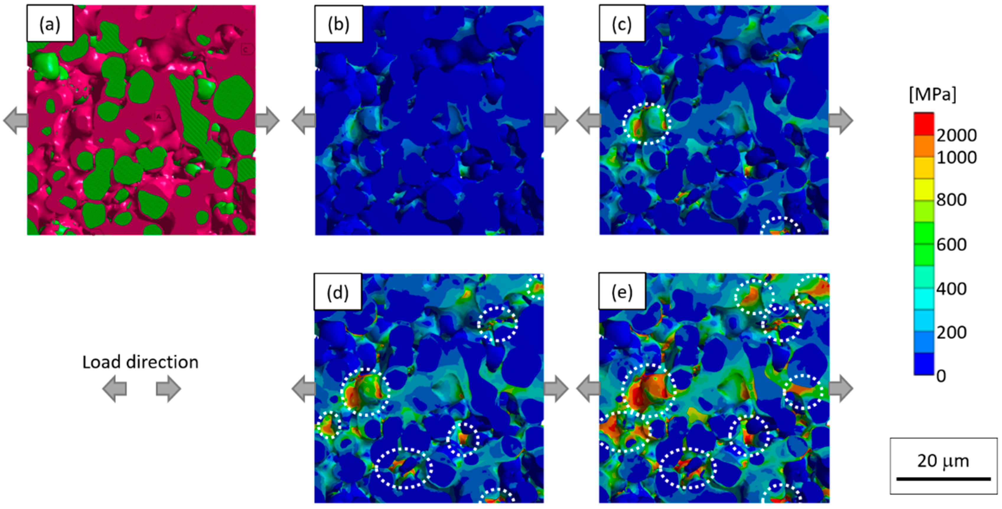
To gain further insights, we now discuss the microscopic deformation characteristics, which include distribution of local stress and strain. Our previous study used die-shear tests to demonstrate the fracture at the Cu-IMC-resin joints within the IMCs or at the interface between the IMCs and Cu particles with brittle surfaces [33]. In addition, Liu et al. [42] demonstrated (both numerically and experimentally) that Cu6Sn5 and Cu3Sn fractured in brittle mode using the micro-cantilever bending method. Although, the precise fracture behavior of brittle materials should be discussed by considering fracture toughness based on various influence factors; here, we have simply discussed the behavior in terms of Mises stress at potential crack initiation sites. The microscopic distribution of Mises stress of the TLPS microstructure against macroscopic uniaxial load was numerically evaluated, where the ambient temperature was set as −55 °C because the maximum macroscopic strain was generated at the minimum temperature stage during the thermal cycling. The results are shown in Figure 11, where it is evident that the stress concentration sites, which are close to the necks between the connected Cu particles, expand with the increase in macroscopic strain (Figure 11b–e). When the macroscopic strain is 0.4% (which is equivalent to that used in thermal cycling experiment), although the stress concentration sites where the local Mises stress exceeds the tensile strength of Cu6Sn5 [42] can be partially identified, it is evident that the stress is broadly distributed (Figure 11c). Further, almost no sites with local Mises stress exceeding the tensile strength of the Cu6Sn5 can be found in the low strain (0.1%) condition (Figure 11b); however, many such sites can be found in the high-strain (1.0%) condition (Figure 11e). Considering the poor ductility of the IMCs, the micro-deformation behavior interestingly indicates that the high reliability of the TLPS joint is limited by this specific condition on the macroscopic strain; further evaluation of the durable strain conditions is of particular interest.
It may be noted that some earlier studies have reported the deformation behavior of TLPS joints under temperature variation. Greve et al. [29] experimentally and numerically identified a new failure mechanism i.e., cooling-induced formation of vertical cracks in Cu-Sn and Ni-Sn TLPS joints based on the stress concentration at the interface of the TLPS layer and DBC substrate. Dudek et al. [27] also numerically investigated Cu-Sn TLPS joint under thermal cycling, where they evaluated the potential failure modes corresponding to the fatigue of chip metallization and brittle fracture of IMC, components, or interfaces. These studies revealed that the brittle fracture modes mainly occurred due to the stiffness and brittleness of the IMCs; therefore, the joint reliability would strongly depend on the stress conditions; i.e., joint dimensions, operation temperature, and so on. In contrast, the proposed Cu-IMC-resin TLPS microstructure exhibited deformation behavior under low-stiffness and broad stress distribution because of its inherent “skeleton-shape”, thereby facilitating the excellent thermal cyclic reliability of the joint. However, a comprise between low stiffness and high thermal conductivity was required for efficient operation; consequently, further optimization of the skeleton microstructure to achieve both low stiffness and high thermal conductivity is of particular interest.

5. Conclusions

We evaluated an inherent microstructure of the TLPS joint, skeleton-shaped Cu-IMC-resin microstructure, using FE simulations based on a 3D image reconstruction model to elucidate its macro- and micro-deformation properties. Macroscopically, the Cu-IMC-resin microstructure showed temperature-stable and low-stiffness mechanical characteristics because the Cu and IMC primarily acted as the load-carrying phases, and the embedded easily-deformable resin acted as the spacer. The homogenized Young’s modulus of the TLPS Cu-IMC-resin microstructure (11 GPa, −89%) was significantly lower than that of Cu6Sn5 (102 GPa, reference). Microscopically, the local stresses were broadly distributed on the IMC parts within the TLPS microstructure under uniaxial tensile simulation. This micro-deformation behavior indicated that the TLPS microstructure can exhibit highly reliable performance under a specific macroscopic strain condition in spite of the poor ductility of the IMCs. SiC-DBC die-attached numerical model using the homogenized mechanical properties of the Cu-IMC-resin predicted its excellent reliability during thermal cycling, as the deformation behavior showed both quite low strain and stress from the macroscopic view, and lower local-stress than the tensile strength of Cu6Sn5 from the microscopic view. This prediction was supported by the experimental results.
The proposed microstructure deformed under low-stiffness due to its inherent skeleton-like shape. However, a balance between low stiffness and high thermal conductivity was crucial for an efficient operation. Therefore, the future scope of this work includes further optimization of the skeleton microstructure to alleviate this compromise.

Author Contributions

Conceptualization, H.T., Y.K. and A.H.; Investigation, H.T.; Methodology, H.T., T.M. and T.S.; Project administration, H.Y.; Resources. H.T. and H.Y.; Supervision, Y.K. and A.H.; Validation, H.T. and H.Y.; Visualization, H.T.; Writing—original draft, H.T.; Writing—review and editing; H.T., T.M., T.S., Y.K. and A.H.

Funding

This research received no external funding.

Acknowledgments

The authors would like to thank S. Kasaki for technical assistance with the finite element analysis.

Conflicts of Interest

The authors declare no conflict of interest.

References

  1. Manikam, V.R.; Cheong, K.Y. Die attach materials for high temperature applications: A review. IEEE Trans. Compon. Packag. Manuf. Technol. 2011, 1, 457–478. [Google Scholar] [CrossRef]
  2. Kisiel, R.; Szczepański, Z. Die-attachment solutions for SiC power devices. Microelectron. Reliab. 2009, 49, 627–629. [Google Scholar] [CrossRef]
  3. Ide, E.; Angata, S.; Hirose, A.; Kobayashi, K.F. Metal-metal bonding process using Ag metallo-organic nanoparticles. Acta Mater. 2005, 53, 2385–2393. [Google Scholar] [CrossRef]
  4. Akada, Y.; Tatsumi, H.; Yamaguchi, T.; Hirose, A.; Morita, T.; Ide, E. Interfacial Bonding Mechanism Using Silver Metallo-Organic Nanoparticles to Bulk Metals and Observation of Sintering Behavior. Mater. Trans. 2008, 49, 1537–1545. [Google Scholar] [CrossRef] [Green Version]
  5. Ogura, T.; Nishimura, M.; Tatsumi, H.; Takahara, W.; Hirose, A. Interfacial Bonding Behavior between Silver Nanoparticles and Gold Substrate Using Molecular Dynamics Simulation. Mater. Trans. 2012, 53, 2085–2090. [Google Scholar] [CrossRef] [Green Version]
  6. Tatsumi, H.; Kumada, S.; Fukuda, A.; Yamaguchi, H.; Kashiba, Y. Impact of Metallurgical and Mechanical Properties of Sintered Silver Nanoparticles on Die-attach Reliability of High-temperature Power Modules. J. Microelectron. Electron. Packag. 2016, 13, 121–127. [Google Scholar] [CrossRef]
  7. Bai, J.G.; Zhang, Z.Z.; Calata, J.N.; Lu, G.Q. Low-temperature sintered nanoscale silver as a novel semiconductor device-metallized substrate interconnect material. IEEE Trans. Compon. Packag. Technol. 2006, 29, 589–593. [Google Scholar] [CrossRef]
  8. Alarifi, H.; Hu, A.; Yavuz, M.; Zhou, Y.N. Silver nanoparticle paste for low-temperature bonding of copper. J. Electron. Mater. 2011, 40, 1394–1402. [Google Scholar] [CrossRef]
  9. Sakamoto, S.; Sugahara, T.; Suganuma, K. Microstructural stability of Ag sinter joining in thermal cycling. J. Mater. Sci. Mater. Electron. 2013, 24, 1332–1340. [Google Scholar] [CrossRef]
  10. Zheng, H.; Berry, D.; Ngo, K.D.T.; Lu, G.Q. Chip-bonding on copper by pressureless sintering of nanosilver paste under controlled atmosphere. IEEE Trans. Compon. Packag. Manuf. Technol. 2014, 4, 377–384. [Google Scholar] [CrossRef]
  11. Fu, S.; Mei, Y.; Lu, G.Q.; Li, X.; Chen, G.; Chen, X. Pressureless sintering of nanosilver paste at low temperature to join large area (≥100 mm2) power chips for electronic packaging. Mater. Lett. 2014, 128, 42–45. [Google Scholar] [CrossRef]
  12. Wang, S.; Li, M.; Ji, H.; Wang, C. Rapid pressureless low-temperature sintering of Ag nanoparticles for high-power density electronic packaging. Scr. Mater. 2013, 69, 789–792. [Google Scholar] [CrossRef]
  13. Chua, S.T.; Siow, K.S. Microstructural studies and bonding strength of pressureless sintered nano-silver joints on silver, direct bond copper (DBC) and copper substrates aged at 300 °C. J. Alloys Compd. 2016, 687, 486–498. [Google Scholar] [CrossRef]
  14. Kähler, J.; Heuck, N.; Wagner, A.; Stranz, A.; Peiner, E.; Waag, A. Sintering of copper particles for die attach. IEEE Trans. Compon. Packag. Manuf. Technol. 2012, 2, 1587–1591. [Google Scholar] [CrossRef]
  15. Yoon, J.-W.; Back, J.-H. Effect of Sintering Conditions on the Mechanical Strength of Cu-Sintered Joints for High-Power Applications. Materials 2018, 11, 2105. [Google Scholar] [CrossRef] [PubMed]
  16. Gao, R.; He, S.; Shen, Y.A.; Nishikawa, H. Effect of Substrates on Fracture Mechanism and Process Optimization of Oxidation–Reduction Bonding with Copper Microparticles. J. Electron. Mater. 2019, 48, 2263–2271. [Google Scholar] [CrossRef]
  17. Greve, H.; Chen, L.Y.; Fox, I.; McCluskey, F.P. Transient liquid phase sintered attach for power electronics. In Proceedings of the 2013 IEEE 63rd Electronic Components and Technology Conference (ECTC), Las Vegas, NV, USA, 28–31 May 2013; pp. 435–440. [Google Scholar]
  18. Lee, B.S.; Yoon, J.W. Cu-Sn Intermetallic Compound Joints for High-Temperature Power Electronics Applications. J. Electron. Mater. 2018, 47, 430–435. [Google Scholar] [CrossRef]
  19. Mokhtari, O.; Nishikawa, H. Transient liquid phase bonding of Sn–Bi solder with added Cu particles. J. Mater. Sci. Mater. Electron. 2016, 27, 4232–4244. [Google Scholar] [CrossRef]
  20. Liu, X.; He, S.; Nishikawa, H. Low temperature solid-state bonding using Sn-coated Cu particles for high temperature die attach. J. Alloys Compd. 2017, 695, 2165–2172. [Google Scholar] [CrossRef]
  21. Hu, T.; Chen, H.; Li, M.; Zhao, Z. Cu@Sn Core—Shell Structure Powder Preform for High-Temperature Applications Based on Transient Liquid Phase Bonding. IEEE Trans. Power Electron. 2016, 32, 441–451. [Google Scholar]
  22. Yoon, S.W.; Glover, M.D.; Shiozaki, K. Nickel-tin transient liquid phase bonding toward high-temperature operational power electronics in electrified vehicles. IEEE Trans. Power Electron. 2013, 28, 2448–2456. [Google Scholar] [CrossRef]
  23. Feng, H.; Huang, J.; Yang, J.; Zhou, S.; Zhang, R.; Chen, S. A Transient Liquid Phase Sintering Bonding Process Using Nickel-Tin Mixed Powder for the New Generation of High-Temperature Power Devices. J. Electron. Mater. 2017, 46, 4152–4159. [Google Scholar] [CrossRef]
  24. Fujino, M.; Narusawa, H.; Kuramochi, Y.; Higurashi, E.; Suga, T.; Shiratori, T.; Mizukoshi, M. Transient liquid-phase sintering using silver and tin powder mixture for die bonding. Jpn. J. Appl. Phys. 2016, 55, 04EC14. [Google Scholar] [CrossRef]
  25. Guth, K.; Heuck, N.; Stahlhut, C.; Ciliox, A.; Oeschler, N.; Ag, I.T. End-of-life investigation on the XT interconnect technology. In Proceedings of the PCIM Europe 2015, Nuremberg, Germany, 19–21 May 2015; pp. 72–79. [Google Scholar]
  26. Guth, K.; Oeschler, N.; Böwer, L.; Speckels, R.; Strotmann, G.; Heuck, N.; Krasel, S.; Ciliox, A. New assembly and interconnect technologies for power modules. In Proceedings of the Integrated Power Electronics Systems (CIPS) 2012 7th International Conference, Nuremberg, Germany, 6–8 March 2012; pp. 1–5. [Google Scholar]
  27. Dudek, R.; Sommer, P.; Fix, A.; Rzepka, S.; Michel, B. Reliability issues for high temperature interconnections based on transient liquid phase soldering. In Proceedings of the 14th International Conference on Thermal, Mechanical and Multi-Physics Simulation and Experiments in Microelectronics and Microsystems (EuroSimE), Wroclaw, Poland, 14–17 April 2013; pp. 1–8. [Google Scholar]
  28. Lee, B.S.; Hyun, S.K.; Yoon, J.W. Cu–Sn and Ni–Sn transient liquid phase bonding for die-attach technology applications in high-temperature power electronics packaging. J. Mater. Sci. Mater. Electron. 2017, 28, 7827–7833. [Google Scholar] [CrossRef]
  29. Greve, H.; Moeini, S.A.; McCluskey, P.; Joshi, S. Prediction and Mitigation of Vertical Cracking in High-Temperature Transient Liquid Phase Sintered Joints by Thermo-Mechanical Simulation. J. Electron. Packag. 2018, 140, 020903. [Google Scholar] [CrossRef]
  30. Shearer, C.; Shearer, B.; Matijasevic, G.; Gandhi, P. Transient liquid phase sintering composites: Polymer adhesives with metallurgical bonds. J. Electron. Mater. 1999, 28, 1319–1326. [Google Scholar] [CrossRef]
  31. Gallagher, C.; Matijasevic, G.; Maguire, J.F. Transient Liquid Phase Sintering Conductive Adhesives. In Proceedings of the 1997 IEEE 47th Electronic Components and Technology Conference (ECTC), San Jose, CA, USA, 18–21 May 1997; pp. 554–560. [Google Scholar]
  32. Zhang, Z.; Wong, C.P. Recent advances in flip-chip underfill: Materials, process, and reliability. IEEE Trans. Adv. Packag. 2004, 27, 515–524. [Google Scholar] [CrossRef]
  33. Tatsumi, H.; Lis, A.; Yamaguchi, H.; Kashiba, Y.; Hirose, A. Evaluation of Stiffness-Reduced Joints by Transient Liquid-Phase Sintering of Copper-Solder-Resin Composite for SiC Die-Attach Applications. IEEE Trans. Compon. Packag. Manuf. Technol. 2019. [Google Scholar] [CrossRef]
  34. Tatsumi, H.; Lis, A.; Yamaguchi, H.; Matsuda, T.; Sano, T.; Kashiba, Y.; Hirose, A. Evolution of Transient Liquid-Phase Sintered Cu-Sn Skeleton Microstructure During Thermal Aging. Appl. Sci. 2019, 9, 157. [Google Scholar] [CrossRef]
  35. Ansys, Inc. ANSYS 18.2 Workbench User’s Guide; Ansys, Inc.: Canonsburg, PA, USA, 2017. [Google Scholar]
  36. Forquin, P.; Denoual, C.; Cottenot, C.E.; Hild, F. Experiments and modelling of the compressive behaviour of two SiC ceramics. Mech. Mater. 2003, 35, 987–1002. [Google Scholar] [CrossRef] [Green Version]
  37. Chen, C.; Choe, C.; Zhang, Z.; Kim, D.; Suganuma, K. Low-stress design of bonding structure and its thermal shock performance (−50 to 250 °C) in SiC/DBC power die-attached modules. J. Mater. Sci. Mater. Electron. 2018, 29, 14335–14346. [Google Scholar] [CrossRef]
  38. Jenkins, W.D.; Digges, T.G.; Johnson, C.R. Tensile properties of copper, nickel, and 70% copper 30% nickel and 30% copper 70% nickel alloys at high temperatures. J. Res. Natl. Bur. Stand. 1957, 58, 201–211. [Google Scholar] [CrossRef]
  39. Deng, X.; Chawla, N.; Chawla, K.K.; Koopman, M. Deformation behavior of (Cu, Ag)-Sn intermetallics by nanoindentation. Acta Mater. 2004, 52, 4291–4303. [Google Scholar] [CrossRef]
  40. Shohji, I.; Yoshida, T.; Takahashi, T.; Hioki, S. Tensile Properties of Sn-3. 5Ag and Sn-3. 5Ag-0. 75Cu Lead-free Solders. Mater. Trans. 2002, 43, 1854–1857. [Google Scholar] [CrossRef]
  41. Lall, P.; Shantaram, S.; Suhling, J.; Locker, D. Effect of aging on the high strain rate mechanical properties of SAC105 and SAC305 leadfree alloys. In Proceedings of the 2013 IEEE 63rd Electronic Components and Technology Conference (ECTC), Las Vegas, NV, USA, 28–31 May 2013; pp. 1277–1293. [Google Scholar]
  42. Liu, L.; Chen, Z.; Liu, C.; Wu, Y.; An, B. Micro-mechanical and fracture characteristics of Cu6Sn5 and Cu3Sn intermetallic compounds under micro-cantilever bending. Intermetallics 2016, 76, 10–17. [Google Scholar] [CrossRef]
  43. Lis, A.; Kicin, S.; Brem, F.; Leinenbach, C. Thermal Stress Assessment for Transient Liquid-Phase Bonded Si Chips in High-Power Modules Using Experimental and Numerical Methods. J. Electron. Mater. 2017, 46, 729–741. [Google Scholar] [CrossRef]
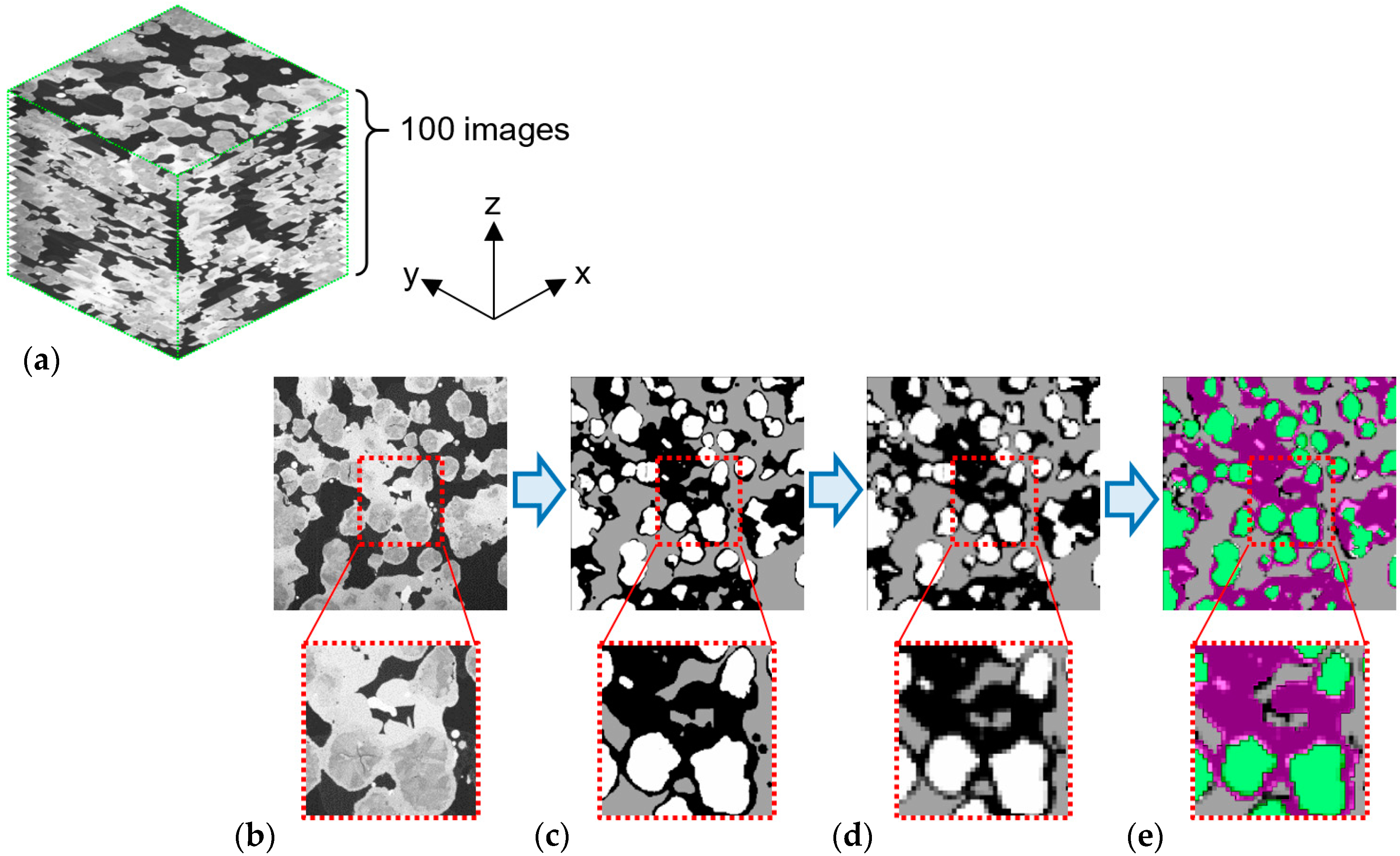
Figure 1. Segmentation flow of the copper- intermetallic compound-resin (Cu-IMC-resin) microstructure composed of Cu, Cu-Sn IMC, and polyimide (PI) resin. (a) Schematic of stacked SEM images, (b) preprocessed SEM image, (c) Otsu segmentation of the image, (d) image after Gaussian smoothing, and (e) resegmentated image.
Applsci 09 03476 g001
Figure 2. Cu-IMC-resin model of size 15 μm for finite element (FE) analysis, which is based on 3D image reconstruction. The model comprises Cu (green), IMC (pink), and resin (light blue).
Applsci 09 03476 g002
Figure 3. Cu-IMC-resin model of size 50 μm for FE analysis, which is based on 3D image reconstruction. The model comprises Cu (green), IMC (pink), and resin (invisible).
Applsci 09 03476 g003
Figure 4. Silicon carbide-direct bonded copper (SiC-DBC) FE model for temperature cycling simulations. The sizes of the SiC chip and DBC substrate are 8 × 8 mm, and 12 × 12 mm, respectively.
Applsci 09 03476 g004
Figure 5. Temperature dependence of the homogenized (a) Young’s modulus and (b) yield strength calculated by the 15-μm-sized models of Cu-IMC-resin and Cu-SAC-resin, where the resin region is PI, epoxy, or air. The values are normalized by that of the Cu-IMC-resin (PI) at 22 °C.
Applsci 09 03476 g005
Figure 6. Deformation properties calculated by the 50-μm-sized Cu-IMC-resin microstructure model based on 3D image reconstruction at 22 °C.
Applsci 09 03476 g006
Figure 7. Unbonded area of TLPS and SAC305 solder joints through 1200 thermal cycles in the temperature range of −55 to 175 °C.
Applsci 09 03476 g007
Figure 8. Cross-sectional SEM image of (a) the TLPS joint after 1,200 thermal cycles and (b) the SAC305 joint after 600 thermal cycles in the temperature range of −55 to 175 °C.
Applsci 09 03476 g008
Figure 9. FE simulation results of total strain distribution (a) at cross-sections along the diagonal axis of the joint and (b) in the transient liquid-phase sintering (TLPS) bonding layer. Simulated Mises stress distribution (c) at cross-sections along the diagonal axis of the joint and (d) in the TLPS bonding layer at minimum temperature during the thermal cycling.
Applsci 09 03476 g009
Figure 10. Evolution of calculated (a) normalized Mises strain and (b) Mises stress in TLPS, SAC305, and IMC (Cu6Sn5) joints during the ten thermal cycles.
Applsci 09 03476 g010
Figure 11. Distribution of Mises stress obtained from the FE analysis of the 50-μm-sized Cu-IMC-resin model against uniaxial displacement at −55 °C. (a) FE model, and the models with uniaxial macroscopic strain of (b) 0.1%, (c) 0.4%, (d) 0.6%, and (e) 1.0%. The areas, whose Mises stress exceeded the tensile strength of Cu6Sn5 (approximately 1000 MPa), are shown by white dotted circles.
Applsci 09 03476 g011
Table 1. FE analysis by 15-μm-sized model.
CaseRegions
ABC
Cu-IMC-resin (PI)CuIMC (Cu6Sn5)Polyimide-resin
Cu-IMC-resin (Epoxy)CuIMC (Cu6Sn5)Epoxy-resin
Cu-IMC-airCuIMC (Cu6Sn5)Air
Cu-SAC-resin (PI)CuSAC305Polyimide-resin
Cu-SAC-resin (Epoxy)CuSAC305Epoxy-resin
Cu-SAC-airCuSAC305Air
Table 2. Summary of selected physical properties used in this study; data is from [36,37,38,39,40,41].
MaterialYoung’s Modulus
E (GPa)
Yield Strength
σY (MPa)
Ultimate Tensile Strength
σUTS (MPa)
CTE
α (10−6/°C)
Poisson’s Ratio
ν
SiC410----3.80.33
Si3N4314----3.00.33
Cu96 (0 °C)52 (0 °C)240 (0 °C)16.70.33
88 (300 °C)42 (300 °C)178 (300 °C)
IMC (Cu6Sn5)102----18.30.31
SAC30546 (RT)45 (RT)58 (RT)21.2 (RT)0.36
35 (100 °C)15 (125 °C) 23 (125 °C)22.0 (100 °C)
4 (200 °C)3 (200 °C)4 (200 °C)22.5 (200 °C)
Table 3. Physical properties of resin used in FE analysis.
Type of ResinYoung’s Modulus
E (GPa)
Yield Strength
σY (MPa)
Ultimate Tensile Strength
σUTS (MPa)
CTE
α (10−6/°C)
Poisson’s Ratio
ν
Polyimide-resin, used in this study0.120 (−40 °C)4.0 (−40 °C)16.4 (−40 °C)38.00.37
0.021 (RT)1.0 (RT)4.0 (RT °C)
0.004 (100 °C)0.2 (100 °C)0.7 (100 °C)
0.001 (150 °C)0.1 (150 °C)0.2 (150 °C)
Epoxy-resin2.0307038.00.37