Article

Ultrathin Acoustic Metasurface Holograms with Arbitrary Phase Control

1
Institute of Marine Electronics Engineering, Zhejiang University, Hangzhou 310058, China
2
Key Laboratory of Ocean Observation-Imaging Testbed of Zhejiang Province, Zhejiang University, Hangzhou 310058, China
3
Key Laboratory of Advanced Micro/Nano Electronic Devices & Smart Systems and Applications of Zhejiang Province, Zhejiang University, Hangzhou 310027, China
*
Author to whom correspondence should be addressed.
Appl. Sci. 2019, 9(17), 3585; https://doi.org/10.3390/app9173585
Submission received: 1 August 2019 / Revised: 25 August 2019 / Accepted: 26 August 2019 / Published: 2 September 2019
(This article belongs to the Special Issue Advanced Active and Passive Metasurfaces)

Abstract

:

Featured Application

medical treatment, microfluidic particle separation.

Abstract

Holograms show great potential in optical or acoustical waves applications due to their capability to reconstruct images. In this paper, we propose a novel scheme to realize acoustic holograms based on an ultrathin metasurface with arbitrary phase control ability. Compared with the conventional imaging method, e.g., concave mirror, which has a bulky size and limited imaging effects, the acoustic metasurface comprises a single layer of Helmholtz-like elements that can largely reduce the complexity of production. With this ultrathin reflective metasurface, acoustic holograms are constructed through a subtle structure design for single and multiple focal imaging, while the potential thermoviscous effects are minimized. We further demonstrate that the metasurface has the capability of arbitrary phase control in a certain frequency range, where the reflected phase dispersion is linear. Our proposed ultrathin metasurface holograms would be very useful in numerous applications, such as acoustic sensing, medical imaging, and so on.

1. Introduction

Acoustic imaging and acoustic focusing have many essential uses in modern science and industry, such as diagnosing disease [1], sensing natural gas seepage [2], visualizing earthquake sources [3], and microfluidic particle separation [4]. Generally, structures such as the concave mirror, convex mirror, and wedge are used to realize focal and imaging effects. However, these structures are bulky and have limited imaging effects. Holography, a revolutionary technique which can realize three-dimensional optical imaging, has gained increasing attention over the last few decades. The traditional optical hologram first records the interference patterns of the scattered light and a coherent reference beam [5,6,7,8], and then, with the recorded phase and amplitude information, it reconstructs the light field to achieve optical imaging. In recent studies, the hologram can also be generated by calculating the phase distribution of the field on the hologram and transforming the phase information into unit structures, a method also known as computer-generated holography (CGH) [9,10,11].
Consisting of only a single layer or a few layers of planar metallic structures, planar metamaterials with subwavelength, or metasurface [12,13,14,15,16,17,18,19], show a rapidly growing interest in this field of research. By making use of the metasurface, the wave front, polarization, phase, and amplitude of the electromagnetic wave can all be manipulated. Unlike conventional optical devices, the metasurface is thin, compact, and capable of controlling phases. Owing to these advantages, the metasurface is opening the path to various applications, such as ultrathin flat lenses [20,21,22], carpet cloaks [23,24,25], and polarization conversion [26]. It has also made compact, efficient, and versatile optical holograms come true [27,28,29].
The holography technique is receiving remarkable success in optical applications, and several acoustic holography imaging regimes are raised due to its promising characteristics [30,31]. Yet, acoustic hologram applications are far less developed compared with optical ones since conventional means of the acoustic hologram requires cumbersome phase-shifting elements which are difficult to fabricate.
Metasurfaces are also applicable in the acoustic field for the manipulation of sound wave propagation. A variety of acoustic metasurfaces have been designed to enable complex and unprecedented functionalities, such as the acoustic cloak [32], beam focusing [33], super absorbers [34], and so on. As one of the bases of the acoustic metasurfaces, Helmholtz-like elements can freely tailor the wave fields by controlling the resonance of the entire structure, such that the phase is fully manipulated [33,35,36]. With the ease of fabrication and facility to control the acoustic wave, such structures have been widely used to showcase multiple features. In analog with the optical metasurface hologram, the acoustic hologram based on the metasurface is accomplished by recording and manipulating acoustic field information.
In this paper, we introduce a reflection type acoustic hologram utilizing ultrathin Helmholtz-like structures. Unlike previous acoustic metasurfaces which work only at a single frequency, the structures of the unit cells are adjusted carefully for the desired manner, which can achieve an arbitrary phase control in a certain frequency range. The phase deviations of these unit cells brought by thermoviscous effects are sufficiently investigated. A single-focal effect is achieved while the multi-focal scenarios are further promoted, showing its ability for arbitrary hologram imaging. Simulations are performed, and the results all possess good consistency with the theoretical prediction, validating the effectiveness in our design.

2. Results and Discussion

We have first designed a planar hologram performance for a single spot focusing effect. As illustrated in Figure 1, the incident acoustic waves impinge on the hologram plane, and a circular focal pattern is obtained by manipulating phases of the reflected waves. Knowing the desired focal image, the calculation of the acoustic field distribution on the hologram plane can be achieved by using the Rayleigh–Sommerfeld diffraction theory [37,38].
U 0 = U 1 exp ( j k d ) 2 π d h d ( 1 d j k ) d s ,
with U 0 and U 1 standing for the acoustic fields at point P 0 ( x 0 , y 0 , z 0 ) on the hologram plane and point P 1 ( x 1 , y 1 , z 1 ) on the image plane, respectively; h denotes the distance between the hologram plane and image plane; d denotes the distance between P 0 and P 1 .
In the actual calculation, the continuous integral area is replaced by several discrete pixel points, and the integral becomes the superposition of acoustic fields on these points. To simplify the calculation, we set U 1 = 1 in a condition where there is an acoustic distribution on the pixel of the image plane, otherwise U 1 will be assigned to 0. Phases of the fields are supposed to be uniform. In this way, amplitude and phase distribution on the hologram plane is obtained.
On the other hand, if amplitude and phase information on the hologram plane is known, field distribution on the image plane can be calculated by taking advantage of integral.
U 1 = U 0 exp ( j k d ) 2 π d h d ( 1 d + j k ) d s ,
with U 1 representing the acoustic field at point P 1 ( x 1 , y 1 , z 1 ) on the image plane.
As depicted in Figure 2a, the focal image we designed is a circular spot located in the center of the image plane with a radius of 10 mm. The distance between the two planes is 20 mm. The calculated amplitude and phase distribution on the hologram plane are shown in Figure 2b,c, respectively. Applying the calculated field information to Equation (2), the recovered focal image is acquired, as shown in Figure 2d. Calculation results show a good consistency with the ideal focal image, proving the validity of the adopted equations.
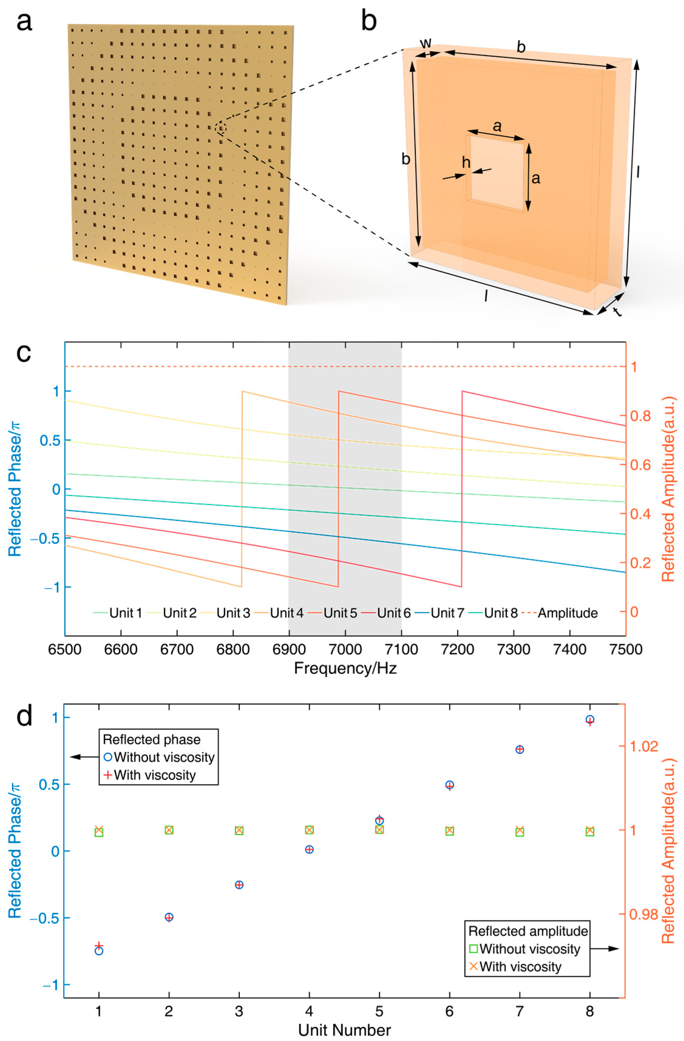
During the actual design, we made the whole hologram plane a flat square with a side length of 200 mm. A general view of the hologram plane is displayed in Figure 3a, with each row and each column comprising 20 unit cells. Helmholtz-like elements were chosen to be the unit cells of our acoustic metasurface. As demonstrated in Figure 3b, the sampled unit cell made of copper, contains a center-positioned cavity, whose geometries are adjustable. In our design, each unit cell’s side length l and thickness t were fixed to be 10 mm and 2.5 mm, respectively. Since the working frequency selected in this paper was 7.0 kHz, the side length and thickness of these unit cells were only about 1/5 and 1/20 of the operating wavelength (49 mm), respectively. Acoustic waves are incident vertically to the holograms and come back with various reflection phases determined by the dimensions of the cavities. Here, 8 different unit cells were designed to obtain 8 different phases, and the corresponding reconstructed amplitudes and phases of the 8 structures were simulated using commercial finite elements package COMSOL Multiphysics 5.3, as illustrated in Figure 3c. It can be clearly seen that under 7.0 kHz, a set of 8 unit cells provided a gradual phase shift from π to π with π / 4 intervals, while the reflection amplitudes were all kept constant. Detailed variable geometry parameters of each unit cell are listed in Table 1. It is worth noting that, since we tuned the structures of the Helmholtz-like unit cells with more degrees of freedom, these 8 different geometry parameters were subtly adjusted, to have almost linear phase dispersion around the working frequency of 7 kHz. As shown in the shadowed region of Figure 3c, the adjacent unit cells had almost the same phase difference in a frequency band from 6.9 kHz to 7.1 kHz. Although with only a narrow band, it shows the possibility to realize hologram not only at a single frequency but also for a certain frequency range.
In real scenarios, to ensure exact phase shift, accurate reflection, and minor acoustic loss, potential airborne thermoviscous effects should be taken into consideration [39]. The viscous property of our structure was directly decided by the geometries of the cavity, which manipulated the interior air path. For these elements, once the side length and thickness of each unit cell were fixed, the other 3 variable parameters (i.e., the neck side length a, the inner cavity side length b, and neck thickness h. Thickness of the inner cavity w is a dependent variable which satisfies w = t − 2h) determined its viscous property and the corresponding metasurface. The reflected amplitudes, as well as phase shifts of each unit cell with and without considering thermoviscous effects, were, therefore, carefully simulated, as demonstrated in Figure 3d. We found that both the amplitude and phase shift variation were negligible. Simulation results indicated that the inaccuracy caused by the thermoviscous effect is small enough to be ignored.
Concerning the aforementioned continuous phase distribution on the hologram plane, together with 8 different reflection phases brought by 8 types of unit cell, we calculated a discrete reflection phase distribution, as illustrated in Figure 4a. Although uniform amplitudes and discrete approximations of the phases were used in the calculation, a fine focal effect was achieved. The image reconstruction of the proposed acoustic metasurface hologram was further simulated. By observing the reflected sound pressure field, the amplitude distribution on the image plane was acquired, as illustrated in Figure 4b. Most of the acoustic energy focused on the center of the image plane, rendering a spot pattern. It indicates that the simulation result is in good agreement with the numeric calculation result, and our metasurface hologram is feasible. In addition, the amplitude distribution considering thermoviscous effects was simulated, as illustrated in Figure 4c, demonstrating a very limited difference compared to the ideal one.
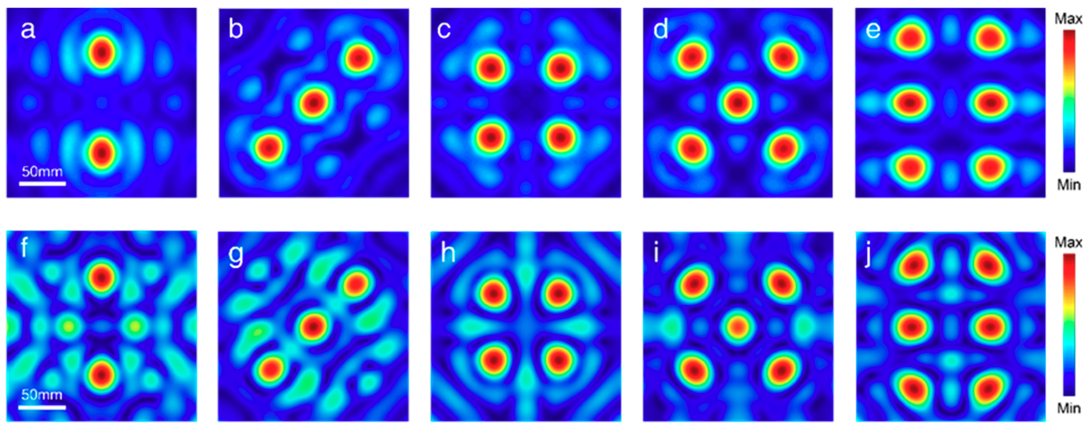
To demonstrate the flexibility of the acoustic metasurface hologram, we also introduced multi-focal holography based on the same methods that single-focal holography uses. Similar to the previous case, we first determined the original imaging patterns, which were 2 to 6 circular spots, respectively. The radius of each spot was 5 mm, while other parameters and settings were identical with the previous case. The phase distributions were calculated afterward. Utilizing the 8 types of the unit cell designed before, we discrete the phase information into 8 levels as well. The phase distributions when 2 to 6 spots were focused on the image plane can be easily calculated using the Rayleigh–Sommerfeld integrals. Referring to these discrete phases, along with the uniform amplitude generated from the unit cells, focal images on the image plane can be calculated, as illustrated in Figure 5a–e.
One can see from the calculation results that discrete phases and uniform amplitudes are capable of realizing good multi-focal effects. Therefore, we conducted simulations on the metasurface-based holograms to validate our theory. The simulation results are illustrated in Figure 5f–j. It indicates a good consistency with the calculated ones, showing a clear multi-focal imaging effect.
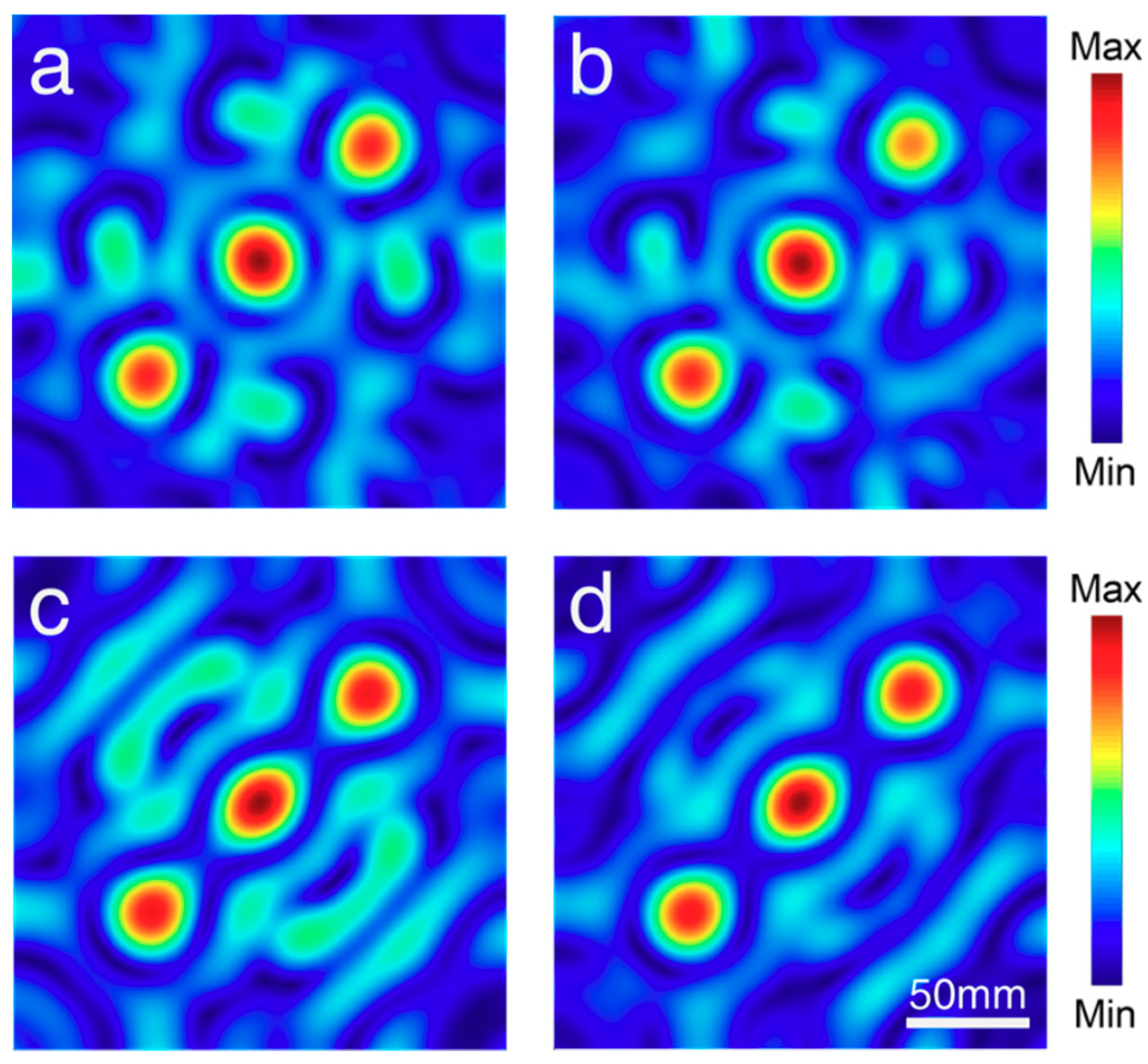
To further show its ability of holographic effect in a certain frequency range, simulations were also performed at different frequency range with the structures of the metasurface kept unchanged. To give an example, here we present a 3-spot focal pattern at the frequency of 6.9, 6.95, 7.05, and 7.1 kHz, respectively, to verify its performance. The results are shown in Figure 6. As aforementioned, the adjacent unit cells have an almost same phase difference in this frequency range, that is to say, the whole metasurface will introduce a global phase deviation in every unit cell, which will not influence the imaging effect at all. However, since the sizes of the whole structure compared with the working wavelength were changed, it shows little divergence in contrast with the original one, as shown in Figure 5g. Nevertheless, the results illustrate equivalent fine imaging performances, validating its capability as a hologram in a certain frequency range.
It should be noted that these unit structures in the metasurface which constitute the holograms have the ability to arbitrarily control the reflection phases. Hence, they are equipped with the potential to render any holographic image at will. In addition, the unit structures are easy to fabricate. With the aid of 3D printing technique, it is convenient to get the entire sample of the metasurface hologram. We may also stitch the separate unit cells together, just like building blocks, to obtain a whole hologram. Due to the advantages mentioned above, the proposed acoustic metasurface holograms may open the gate for various applications in real life.

3. Conclusions

In conclusion, we designed a series of the acoustic metasurface, which allows arbitrary control of the reflection phase to build the holograms. Ultrathin Helmholtz-like structures were chosen to be the unit cells of our metasurface, which are convenient to be produced with 3D printing technology. Thermoviscous effects on the holographic imaging were sufficiently calculated and simulated. Simulation results indicate that the designed metasurface hologram can achieve single-focal imaging and also multi-focal imaging effects in a certain frequency range, confirming the effectiveness and flexibility of the proposed scheme. Such work expands the route to acoustic imaging devices and would be very useful in future applications including medical treatment and ocean exploration.

Author Contributions

B.Z. conceived the original ideal. W.G. and R.Z. designed the metasurface structure. R.Z. and Z.W. completed numeral calculations. W.G. and R.Z. performed simulations. Z.X. and H.W. interpreted the results. W.G., R.Z. and B.Z. produced the manuscript. All authors participated in discussions and reviewed the manuscript.

Funding

This work was sponsored by the National Natural Science Foundation of China under Grants No. 61625502, No. 61574127, No. 61601408, No. 61775193, and No. 11704332, the ZJNSF under Grant No. LY17F010008 and No. LY19F010015, the Top-Notch Young Talents Program of China, the Fundamental Research Funds for the Central Universities, and the Innovation Joint Research Center for Cyber-Physical-Society System.

Conflicts of Interest

The authors declare no conflict of interest.

References

  1. Kompisk, M.; Pasterkamp, H.; Wodicka, G.R. Acoustic imaging of the human chest. Chest 2012, 120, 1309–1321. [Google Scholar] [CrossRef] [PubMed]
  2. Von Deimling, J.S.; Greinert, J.; Chapman, N.R.; Rabbel, W.; Linke, P. Acoustic imaging of natural gas seepage in the North Sea: Sensing bubbles controlled by variable currents. Limnol. Oceanogr. Methods 2010, 8, 155–171. [Google Scholar] [CrossRef]
  3. Rietbrock, A.; Scherbaum, F. Acoustic imaging of earthquake sources from the Chalfant Valley, 1986, aftershock series. Geophys. J. Int. 1994, 119, 260–268. [Google Scholar] [CrossRef] [Green Version]
  4. Piyasena, M.E.; Suthanthiraraj, P.P.A.; Applegate, R.W., Jr.; Goumas, A.M.; Woods, T.A.; López, G.P.; Graves, S.W. Multinode acoustic focusing for parallel flow cytometry. Anal. Chem. 2012, 84, 1831–1839. [Google Scholar] [CrossRef] [PubMed]
  5. Gabor, D. A new microscopic principle. Nature 1948, 161, 777–778. [Google Scholar] [CrossRef] [PubMed]
  6. Leith, E.N.; Upatnieks, J. Reconstructed wavefronts and communication theory. J. Opt. Soc. Am. 1962, 52, 1123–1130. [Google Scholar] [CrossRef]
  7. Scheuer, J.; Yifat, Y. Metasurfaces make it practical. Nat. Nanotechnol. 2015, 10, 296–298. [Google Scholar] [CrossRef]
  8. Schnars, U.; Falldorf, J.W.C.; Jüptner, W. Digital Holography and Wavefront Sensing: Principles, Techniques and Applications; Springer: Berlin/Heidelberg, Germany, 2015; pp. 39–68. [Google Scholar]
  9. Wyrowski, F.; Hauck, R.; Bryngdahl, O. Computer-generated holography: Hologram repetition and phase manipulations. J. Opt. Soc. Am. A 1987, 4, 694–698. [Google Scholar] [CrossRef]
  10. Kelly, D.P.; Monaghan, D.S.; Pandey, N.; Kozacki, T.; Michalkiewicz, A.; Finke, G.; Hennelly, B.M.; Kujawinska, M. Digital holographic capture and optoelectronic reconstruction for 3-D displays. Int. J. Digit. Multimed. Broadcast. 2010, 2010. [Google Scholar] [CrossRef]
  11. Slinger, C.; Cameron, C.; Stanley, M. Computer-generated holography as a generic display technology. Computer 2005, 38, 46–53. [Google Scholar] [CrossRef]
  12. Yu, N.; Genevet, P.; Kats, M.A.; Aieta, F.; Tetienne, J.P.; Capasso, F.; Gaburro, Z. Light propagation with phase discontinuities: Generalized laws of reflection and refraction. Science 2011, 334, 333–337. [Google Scholar] [CrossRef] [PubMed]
  13. Ni, X.; Emani, N.K.; Kildishev, A.V.; Boltasseva, A.; Shalaev, V.M. Broadband light bending with plasmonic nanoantennas. Science 2012, 335, 427. [Google Scholar] [CrossRef] [PubMed]
  14. Sun, S.; He, Q.; Xiao, S.; Xu, Q.; Li, X.; Zhou, L. Gradient-index meta-surfaces as a bridge linking propagating waves and surface waves. Nat. Mater. 2012, 11, 426–431. [Google Scholar] [CrossRef] [PubMed]
  15. Yin, X.; Ye, Z.; Rho, J.; Wang, Y.; Zhang, X. Photonic spin Hall effect at metasurfaces. Science 2013, 339, 1405–1407. [Google Scholar] [CrossRef] [PubMed]
  16. Yang, Y.; Jing, L.; Zheng, B.; Hao, R.; Yin, W.; Li, E.; Soukoulis, C.M.; Chen, H. Full-Polarization 3D Metasurface Cloak with Preserved Amplitude and Phase. Adv. Mater. 2016, 28, 6866–6871. [Google Scholar] [CrossRef] [PubMed]
  17. Wang, Z.; Jia, H.; Yao, K.; Cai, W.; Chen, H.; Liu, Y. Circular Dichroism Metamirrors with Near-Perfect Extinction. ACS Photonics 2016, 3, 2096–2101. [Google Scholar] [CrossRef]
  18. Yang, Y.; Jing, L.; Shen, L.; Wang, Z.; Zheng, B.; Wang, H.; Li, E.; Shen, N.-H.; Koschny, T.; Soukoulis, C.M.; et al. Hyperbolic spoof plasmonic metasurfaces. NPG Asia Mater. 2017, 9, e428. [Google Scholar] [CrossRef]
  19. Qian, C.; Lin, X.; Yang, Y.; Xiong, X.; Wang, H.; Li, E.; Kaminer, I.; Zhang, B.; Chen, H. Experimental observation of superscattering. Phys. Rev. Lett. 2019, 122, 063901. [Google Scholar] [CrossRef]
  20. Aieta, F.; Genevet, P.; Kats, M.A.; Yu, N.; Blanchard, R.; Gaburro, Z.; Capasso, F. Aberration-free ultrathin flat lenses and axicons at telecom wavelengths based on plasmonic metasurfaces. Nano Lett. 2012, 12, 4932–4936. [Google Scholar] [CrossRef]
  21. Chen, X.; Huang, L.; Mühlenbernd, H.; Li, G.; Bai, B.; Tan, Q.; Jin, G.; Qiu, C.-W.; Zhang, S.; Zentgraf, T. Dual-polarity plasmonic metalens for visible light. Nat. Commun. 2012, 3, 1198. [Google Scholar] [CrossRef]
  22. Ni, X.; Ishii, S.; Kildishev, A.V.; Shalaev, V.M. Ultra-thin, planar, Babinet-inverted plasmonic metalenses. Light Sci. Appl. 2013, 2, e72. [Google Scholar] [CrossRef]
  23. Zheng, B.; Zhu, R.; Jing, L.; Yang, Y.; Shen, L.; Wang, H.; Wang, Z.; Zhang, X.; Liu, X.; Li, E.; et al. 3D Visible-Light Invisibility Cloak. Adv. Sci. 2018, 5. [Google Scholar] [CrossRef] [PubMed]
  24. Wang, C.; Yang, Y.; Liu, Q.; Liang, D.; Zheng, B.; Chen, H.; Xu, Z.; Wang, H. Multi-frequency metasurface carpet cloaks. Opt. Express 2018, 26, 14123–14131. [Google Scholar] [CrossRef] [PubMed]
  25. Yang, Y.; Wang, H.; Yu, F.; Xu, Z.; Chen, H. A metasurface carpet cloak for electromagnetic, acoustic and water waves. Sci. Rep. 2016, 6, 20219. [Google Scholar] [CrossRef] [PubMed] [Green Version]
  26. Hao, J.; Yuan, Y.; Ran, L.; Jiang, T.; Kong, J.A.; Chan, C.T.; Zhou, L. Manipulating electromagnetic wave polarizations by anisotropic metamaterials. Phys. Rev. Lett. 2007, 99, 063908. [Google Scholar] [CrossRef] [PubMed]
  27. Ni, X.; Kildishev, A.V.; Shalaev, V.M. Metasurface holograms for visible light. Nat. Commun. 2013, 4, 2807. [Google Scholar] [CrossRef]
  28. Zheng, G.; Mühlenbernd, H.; Kenney, M.; Li, G.; Zentgraf, T.; Zhang, S. Metasurface holograms reaching 80% efficiency. Nat. Nanotechnol. 2015, 10, 308–312. [Google Scholar] [CrossRef]
  29. Wang, Q.; Zhang, X.; Xu, Y.; Gu, J.; Li, Y.; Tian, Z.; Singh, R.; Zhang, S.; Han, J.; Zhang, W. Broadband metasurface holograms: Toward complete phase and amplitude engineering. Sci. Rep. 2016, 6, 32867. [Google Scholar] [CrossRef]
  30. Melde, K.; Mark, A.G.; Qiu, T.; Fischer, P. Holograms for acoustics. Nature 2016, 537, 518–522. [Google Scholar] [CrossRef]
  31. Marzo, A.; Seah, S.A.; Drinkwater, B.W.; Sahoo, D.R.; Long, B.; Subramanian, S. Holographic acoustic elements for manipulation of levitated objects. Nat. Commun. 2015, 6, 8661. [Google Scholar] [CrossRef] [Green Version]
  32. Zhu, R.; Zheng, B.; Ma, C.; Xu, J.; Fang, N.; Chen, H. A broadband polygonal cloak for acoustic wave designed with linear coordinate transformation. J. Acoust. Soc. Am. 2016, 140, 95–101. [Google Scholar] [CrossRef] [PubMed]
  33. Li, Y.; Jiang, X.; Liang, B.; Cheng, J.-C.; Zhang, L. Metascreen-based acoustic passive phased array. Phys. Rev. Appl. 2015, 4, 024003. [Google Scholar] [CrossRef]
  34. Ma, G.; Yang, M.; Xiao, S.; Yang, Z.; Sheng, P. Acoustic metasurface with hybrid resonances. Nat. Mater. 2014, 13, 873–878. [Google Scholar] [CrossRef] [PubMed]
  35. Li, Y.; Qi, S.; Assouar, M.B. Theory of metascreen-based acoustic passive phased array. New J. Phys. 2016, 18, 043024. [Google Scholar] [CrossRef]
  36. Schwan, L.; Umnova, O.; Boutin, C. Sound absorption and reflection from a resonant metasurface: Homogenisation model with experimental validation. Wave Motion 2017, 72, 154–172. [Google Scholar] [CrossRef] [Green Version]
  37. Qi, S.; Assouar, M.B. Ultrathin acoustic metasurfaces for reflective wave focusing. J. Appl. Phys. 2018, 123, 234501. [Google Scholar] [CrossRef] [Green Version]
  38. Rayleigh, J.W.S.B. The Theory of Sound; Macmillan: London, UK, 1896; Volume 2, p. 154. [Google Scholar]
  39. Veerman, J.A.; Rusch, J.J.; Urbach, H.P. Calculation of the Rayleigh–Sommerfeld diffraction integral by exact integration of the fast oscillating factor. J. Opt. Soc. Am. A 2005, 22, 636–646. [Google Scholar] [CrossRef]
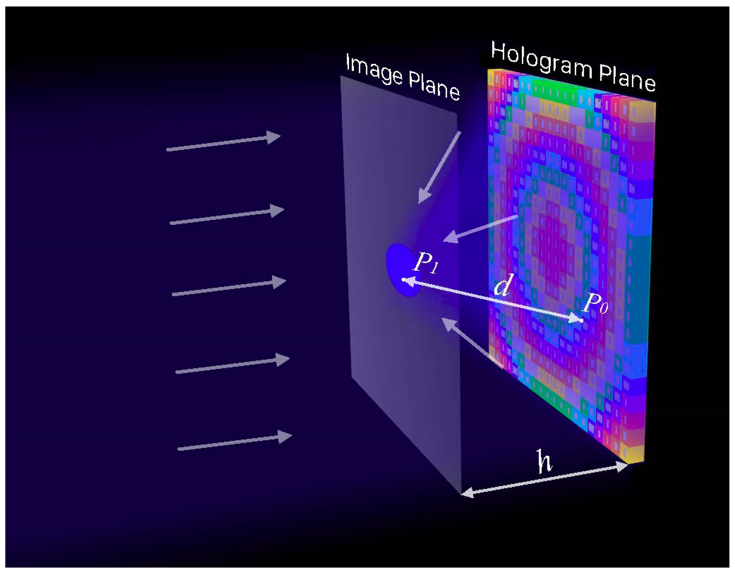
Figure 1. Scheme of the acoustic focusing with a hologram. A series of acoustic waves are incident onto the hologram plane vertically and reflected to focus on the image plane, which is parallel to the hologram plane. The different colors represent the different reflection phases for the incident acoustic wave.
Applsci 09 03585 g001
Figure 2. Calculated acoustic field distributions in the single-focal scenario. (a) Desired acoustic field pattern for the hologram. The black square is the image plane, and acoustic fields are expected to concentrate on the orange spot. (b) Calculated amplitude distribution of the acoustic field on the hologram plane. (c) Calculated phase distribution of the acoustic field on the hologram plane. (d) Calculated amplitude distribution of the acoustic field on the image plane. The distance between the two planes is 20 mm.
Applsci 09 03585 g002
Figure 3. Unit cell of the hologram and the thermoviscous analysis. (a) Perspective view of an acoustic metasurface hologram. The designed hologram consisted of 400 unit cells. (b) A typical unit cell of the metasurface. The side length and the thickness of each unit cell were determined (d = 10 mm, t = 2.5 mm) while other three parameters (i.e., a, b, and h) were variable. (c) The reflected amplitudes and phases of unit cells under the frequency range between 6.5 kHz and 7.5 kHz. The scattering phase can be modulated by altering the geometry characteristics of the cavity. (d) Amplitude and phase shift profiles at 7.0 kHz with and without considering thermoviscous effects.
Applsci 09 03585 g003
Figure 4. Acoustic field distributions in the single-focal scenario. (a) Calculated discrete phase distribution of the acoustic field on the hologram plane. (b) Simulated amplitude distribution of the reflected acoustic field on the hologram plane without considering thermoviscous effects. (c) Simulated amplitude distribution of the reflected acoustic field on the hologram plane considering thermoviscous effects. The simulation settings were kept consistent with the calculated ones.
Applsci 09 03585 g004
Figure 5. Amplitude distributions in multi-focal scenarios. (ae) Calculated amplitude distributions of the acoustic field on the image plane when 2 to 6 spots were projected as the focal pattern, respectively. These amplitude distributions were rebuilt by discretized phases and a constant amplitude on the metasurface hologram planes. (fj) Simulated amplitude distributions of the scattered acoustic field on the image plane. The distance between the two planes was 20 mm.
Applsci 09 03585 g005
Figure 6. Simulated acoustic amplitude distributions under different working frequencies. (ad) The imaging distance is 20 mm while the working frequency was 6.9 kHz, 6.95 kHz, 7.05 kHz, and 7.1 kHz, respectively.
Applsci 09 03585 g006
Table 1. Geometry parameters of unit cells in a period (f = 7.0 kHz).
NumberPhase [deg]a [mm]b [mm]h [mm]w [mm]
1−1352.29.50.501.5
2−902.79.50.252.0
3−453.09.00.351.8
400.48.50.501.5
5451.69.50.501.5
6901.89.00.351.8
71351.88.50.301.9
81802.29.50.351.8