Article

A Novel Analytical Method of Inductance Identification for Direct Drive PMSM with a Stator Winding Fault Considering Spatial Position of the Shorted Turns

1
School of Electrical Engineering and Automation, Henan Polytechnic University, Jiaozuo 454000, Henan, China
2
College of Electric Engineering, Zheng Zhou University, Zheng Zhou 450001, Henan, China
3
Department of Electrical Engineering and Electronics, University of Liverpool, Liverpool L69 7ZX, UK
*
Author to whom correspondence should be addressed.
Appl. Sci. 2019, 9(17), 3599; https://doi.org/10.3390/app9173599
Submission received: 20 July 2019 / Revised: 29 August 2019 / Accepted: 29 August 2019 / Published: 2 September 2019

Abstract

:
This paper presents a novel analytical method (NAM) of inductance identification for a direct drive permanent magnet synchronous motor (DDPMSM) with a stator winding fault (SWF), which considers the spatial position of the shorted turns. First, the structure of the DDPMSM is introduced and its key parameters are reported. Second, the NAM on the inductance identification is elaborated. The inductance analytical expressions of the faulty coil are derived in detail, in which the inductances of the faulty coil and the fault branch can be quickly calculated according to the spatial position coordinates of fault turns. Then, the model of DDPMSM with SWF is established. Finally, using the NAM, finite-element method (FEM), and the simplified analytical method (SAM), the inductances of the faulty coil and the branch are calculated under different fault conditions. Additionally, the fault current of the faulty coil is also studied, where the value of the fault current reflects the fault severity. The comparisons among the FEM, NAM, and SAM show that the accuracy of the NAM is higher than that of the SAM.

1. Introduction

The direct drive permanent magnet synchronous motor (DDPMSM) has the merits of high torque density, high efficiency, and high power factor, suitable for electric propulsion applications, such as in aerospace, robotics, electric vehicles, and so on [1,2,3]. For these applications, high reliability, good fault tolerance, and high precision control are required. However, the stator winding fault has a negative impact on the motor performance, which may cause accidents and even lead to human casualties [4]. Therefore, modeling of the motor with a fault is very significant to predict its behavior, in which the inductance parameters’ identification determines the accuracy of the model [5]. Hence, research on the inductance identification has received significant attention by scholars at home and abroad.
In recent years, numerous methods reported in the literature on the inductance identification can be divided into four categories: the multi-loop method (MLM), the equivalent magnetic network method (EMNM), the winding function method (WFM), and the finite element method (FEM). The basic principle of MLM is to build equations for the voltages and flux linkages according to the actual circuit loops of the motor, where the winding disposition can be considered [6]. However, the circuit loop distributions are different under different fault conditions. Therefore, different types of models with stator winding faults need be established by the MLM, which is not universal. Based on the principle of the equivalent flux tube, the complex magnetic field in the motor is converted into an impedance network by the EMNM [7]. Then, the corresponding inductance parameters are obtained by calculating the equivalent permeability and flux of each circuit. This method can reflect the essence of the motor, but its calculation process is tedious [8]. The WFM provides an effective method to estimate inductance from windings and air gap data, in which the magnetomotive force and gap permeability of the motor are determined by the winding structure [9,10]. However, WFT is suitable for a motor with small air gap width. It is difficult to provide accurate results for a motor with a large air-gap width, for example, the DDPMSM. All the methods mentioned above have the same shortcoming in that they cannot evaluate motor performances under the inter-turn short circuit fault (ITSCF) in different positions of the same slot. The FEM considers the influence of spatial harmonics, winding configurations, core saturation, and so on, which can accurately calculate the inductance of the motor in any fault condition. However, this method needs to perform a new simulation for every fault configuration and requires too much CPU time [11,12]. In addition, it is also not very appropriate for parametric studies. Therefore, a novel analytical method (NAM) of inductance identification is proposed herein, which considers the spatial position of shorted turns in the stator winding fault (SWF).
The remainder of the paper is organized as follows: The structure and some main parameters are introduced in the Section 2. In Section 3, the inductance analytical expressions of the faulty coil are derived in detail, in which the spatial position of the shorted turns in the ITSCF is considered. Then, the model of the DDPMSM with SWF is established in Section 4. In the Section 5, to verify the theoretical investigations on the inductance calculations, the inductances of the faulty coil and the branch calculated by the NAM are compared with those obtained by the FEM and simplified analytical method (SAM) for the same motor. Moreover, the fault current is also studied in this section. Finally, Section 6 presents a brief summary of this paper.

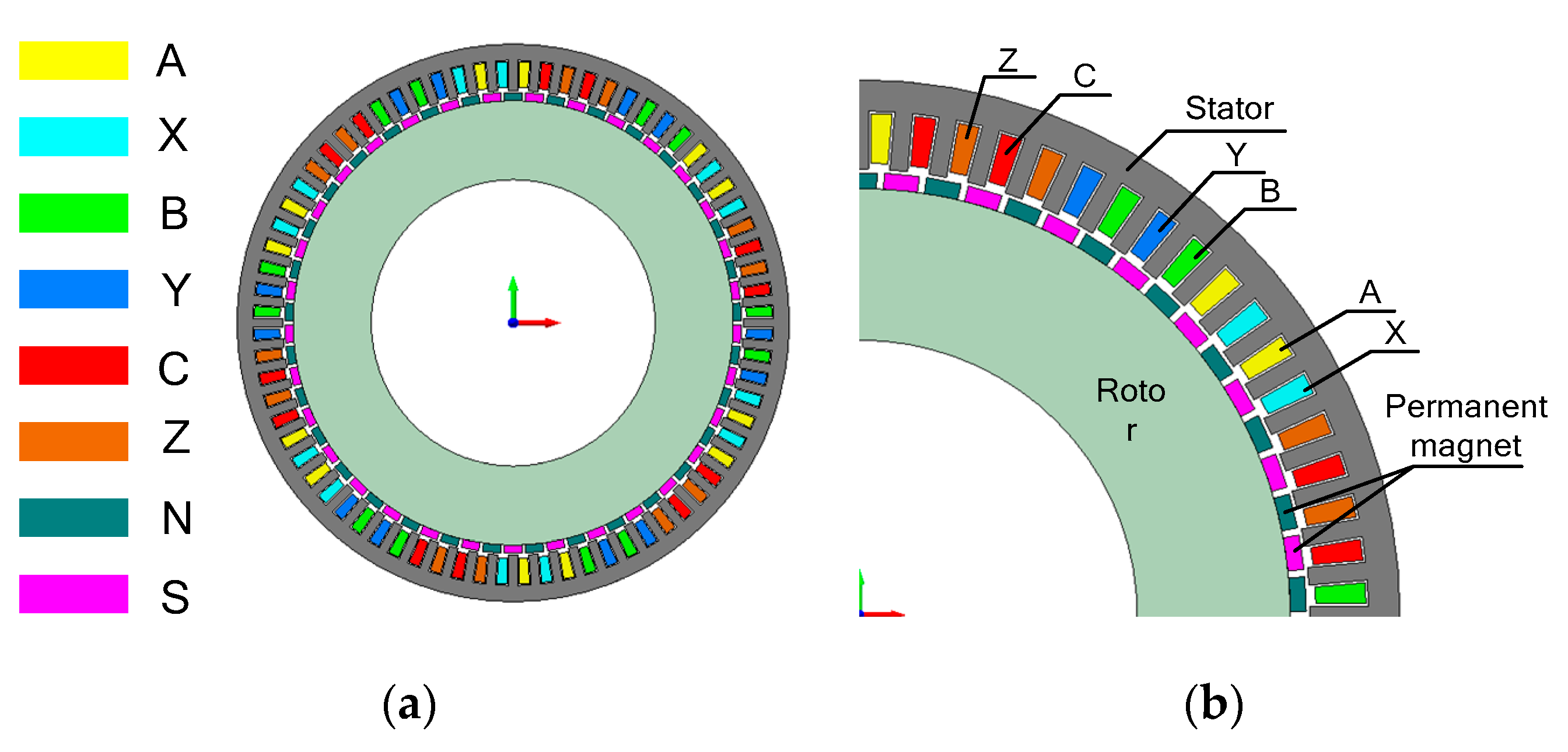
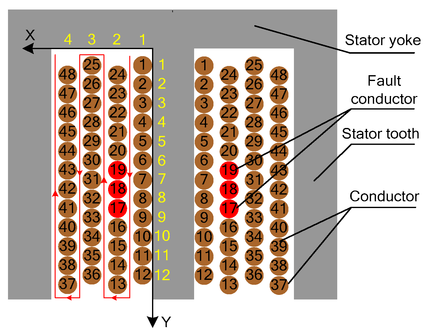
2. Structure and Parameters of the DDPMSM

The structure of the DDPMSM is shown in Figure 1, in which the fractional slot concentrated winding with alternate teeth wound winding topology is adopted. Additionally, each-phase winding is composed of three branches in parallel, and each branch is composed of four 48-turn coils in series. The main parameters of the DDPMSM are reported in Table 1.

3. Inductance Identification and Inductance Analytical Expressions

3.1. SAM

When the motor has an ITSCF, the inductances of the faulty coil can generally be calculated by Equations (1)–(3), which is a SAM [13]:
L i = μ 2 L i
L i = ( 1 μ ) 2 L i
M i , j = μ ( 1 μ ) L i
where the parameter μ is equal to the ratio between the number of short-circuited turns N f and the total turns N t in the faulty coil. L i means the self-inductance of the faulty part in the faulty coil. L i is the self-inductance of the healthy part in the faulty coil, and the mutual inductance between the faulty part and healthy part is denoted by M i , j .
Since the inductances actually have a non-linear relation with the number of turns, the parameter μ cannot be used to model the inductive elements for generic motor, as μ is linearly dependent on the number of short-circuited turns. Furthermore, the SAM mentioned above does not consider the spatial position of the shorted turns. Therefore, a NAM is proposed to accurately calculate the inductances of the faulty coil.

3.2. The Proposed NAM

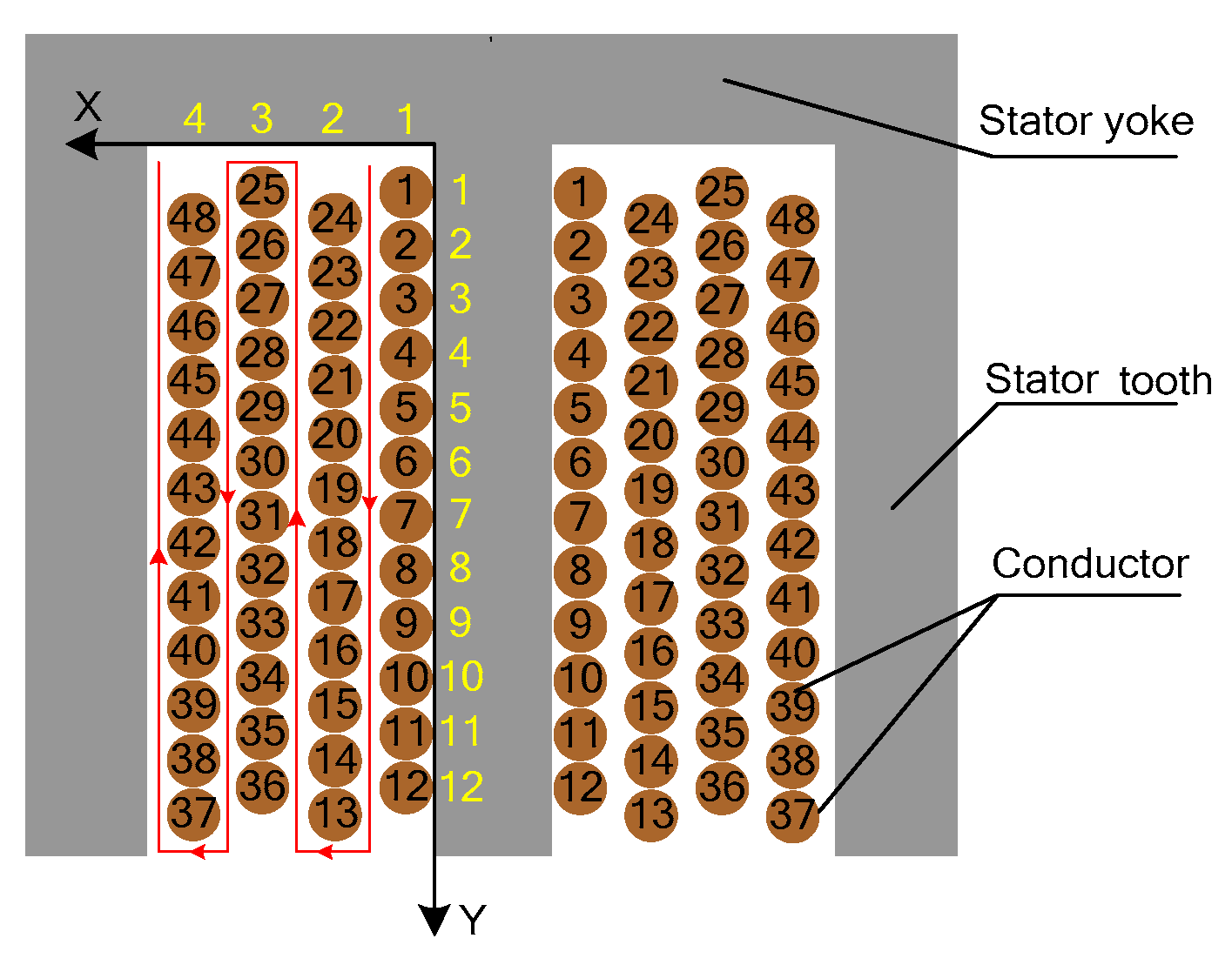
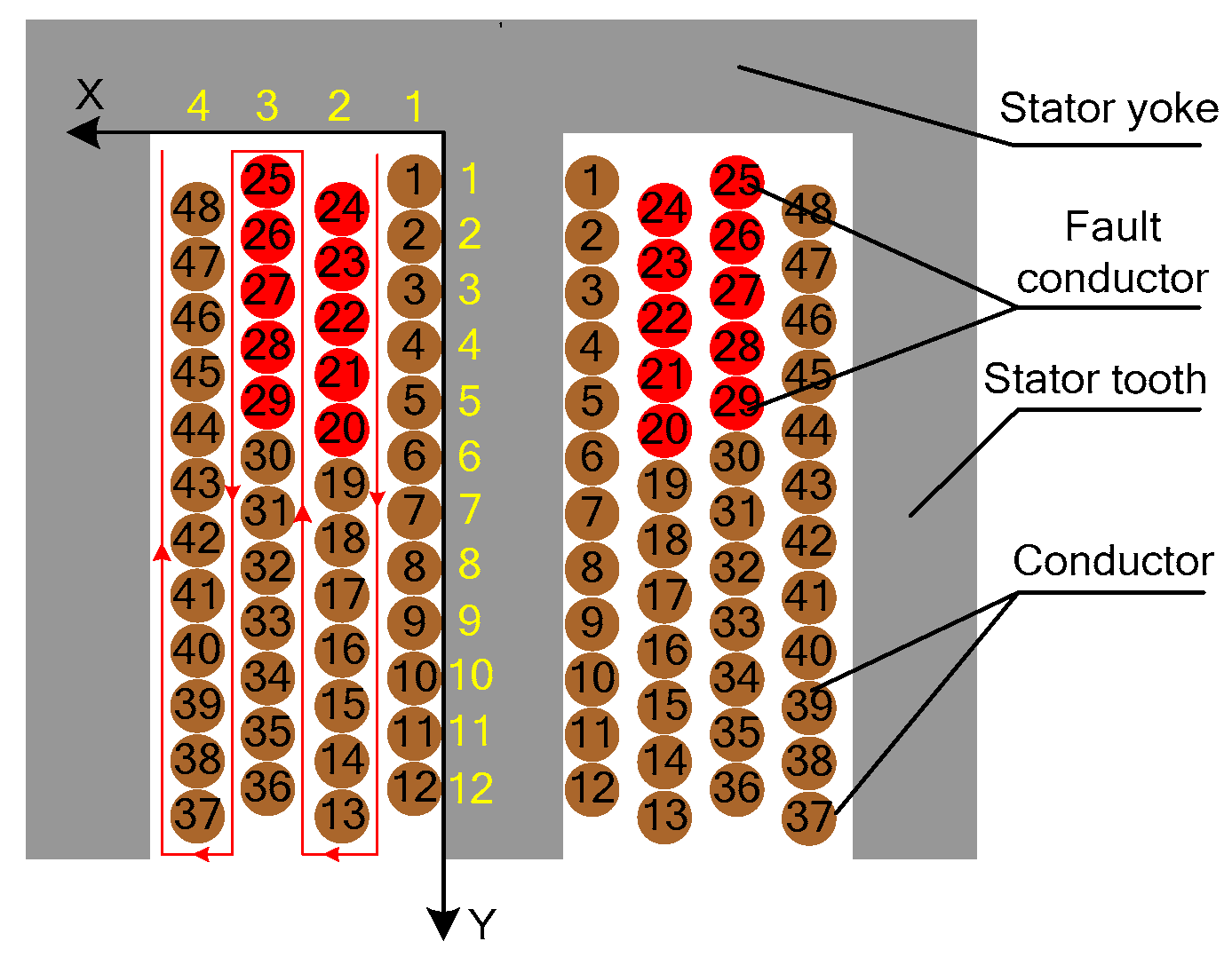
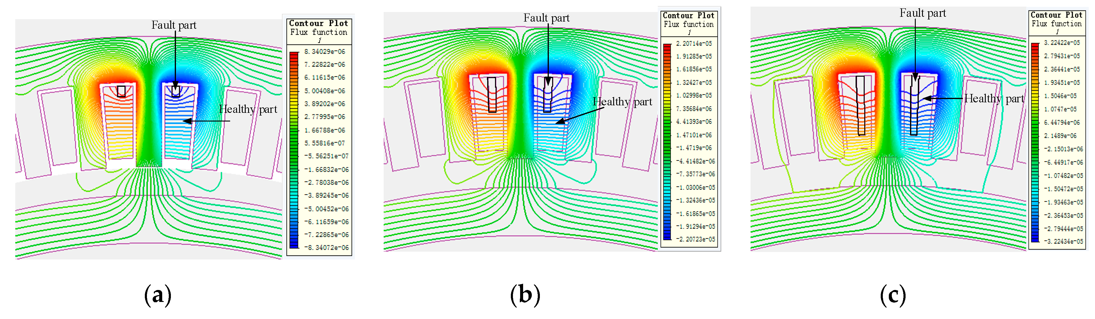
3.2.1. Inductances Identification of Fault Coils in the Slot Considering Spatial Position

Since conductors in the same slot do not share the slot-leakage flux equally, the inductance differs as the position changes, as shown in Figure 2. Figure 3 shows the distribution of the turns in the stator slot. It can be seen that all turns in slot are numbered from 1 to 48 and divided into four layers and two turns per layer. Additionally, the rectangular coordinate is established to accurately define the location of the fault turns in the slot. X is the number of layers, and Y is the slot depth of the turns at each layer. To indicate the inter-layer short circuit fault, the symbol of W is introduced. When W = 1, it means that the short circuit fault is occurred between the first and second layers. W = 2 indicates that the turns of the second and third layers are short-circuit. W = 3 shows the short circuit fault is occurred between the first and second layers.
Therefore, when the coordinate of inter-layer short circuit fault is (W,Y), the number of the first turn in the faulty part can be obtained by Equation (4). Similarly, the number of the last turn in the faulty part can be obtained according to Equation (5). For example, when the inter-layer short circuit occurs at (2,5), it can be calculated from Equations (4) and (5) that the fault turns are located from turn no. 20 to turn no. 29, as shown in Figure 4.
b s = 13 W 2 + 64 W 51 + ( 1 ) W + 1 Y
b f = 13 W 2 + 64 W 51 + ( 1 ) W + 1 Y
When the short circuit fault occurs in the same layer and the coordinate of the faulty part is from (X1, Y1) to (X1, Y2). The number of the first and last turn in the faulty part can be obtained by Equations (6) and (7), respectively. As a result, the fault turns consist of the turns numbered b s b f . For example, when the inter-layer short circuit fault occurs from (2,5) to (2,7), the faulty part is composed of the turns at no. 18, no. 19, and no. 20, as shown in Figure 5.
b s = 12 X 1 1 + Y 1
b f = 12 X 2 1 + Y 1
After getting the turn numbers of the faulty part, the position matrix C 2 , 48 of the faulty coil is established according to the position of the turns. In the first row of the position matrix, all the column elements whose serial number is the fault turn number are set to 1, and the other column elements are all set to 0. Additionally, all the column elements in the second row are opposite to elements in the first row. Then, it is necessary to establish the inductance matrix L (Equation (8)), in which L i j means the mutual inductance between the turns numbered i and j. When i = j, L i j means the self-inductance of the turn numbered i. Afterwards, a second-order matrix L X Q is calculated by Equation (9), and it consists of the inductances of healthy and fault parts:
L = [ L 1 M 1 , 2 M 2 , 1 L 2   M 1 , 47     M 1 , 48 M 2 , 47       M 2 , 48 M 47 , 1 M 48 , 1 M 47 , 2 M 48 , 2   L 47 M 48 , 47 M 47 , 48 L 48 ]
L X Q = C 2 , 48 · L · C 2 , 48 T

3.2.2. Inductances’ Identification of Branches Considering Spatial Position

When there are multiple branches shorted at the same time, the stator circuit schematic is as shown in Figure 6. The inductance matrix of coil L (10) must be obtained, in which L i j means the mutual inductance between the coils numbered i and j. When i = j , L i j represents the self-inductance of the coil numbered i. Since all coils are divided into two parts, the inductance matrix of coils is a 72nd-order matrix.
L = [ L a 11 h M a 11 f a 11 h M b 22 h a 11 h M c 34 h a 11 h M c 34 f a 11 h M a 11 h a 11 f L a 11 f M b 22 h a 11 f M c 34 h a 11 f M c 34 f a 11 f M a 11 h b 21 f M a 11 f b 21 f M b 22 h b 21 f M c 34 h b 21 f M c 34 f b 21 f M a 11 h b 22 h M a 11 f b 22 h L b 22 h M c 34 h b 22 h M c 34 f b 22 h M a 11 h b 22 f M a 11 f b 22 f M b 22 h b 22 f M c 34 h b 22 f M c 34 f b 22 f M a 11 h c 33 f M a 11 f c 33 f M b 22 h c 33 f M c 34 h c 33 f M c 34 f c 33 f M a 11 h c 34 h M a 11 f c 34 h M b 22 h c 34 h L c 34 h M c 34 f c 34 h M a 11 h c 34 f M a 11 f c 34 h M b 22 h c 34 f M c 34 h c 34 f L c 34 f ]
L A B C f = C N e , 72 · L · C N e , 72 T
To calculate the inductances of the branch, the position matrix C N e , 72 of the branch coils is established, in which N e is equal to the sum of the branch number and the faulty coil number. The element of c i , j in the position matrix indicates that whether the coil j belongs to the branch i. The value is set to 1 when the coil j belongs to the fault branch i, otherwise it is 0. Based on the position matrix and inductance matrix, the inductance matrix L A B C f is calculated by Equation (11) and it is a N e th-order matrix. The inductances of all branches, including the fault branch, can be acquired from the inductance matrix L A B C f .

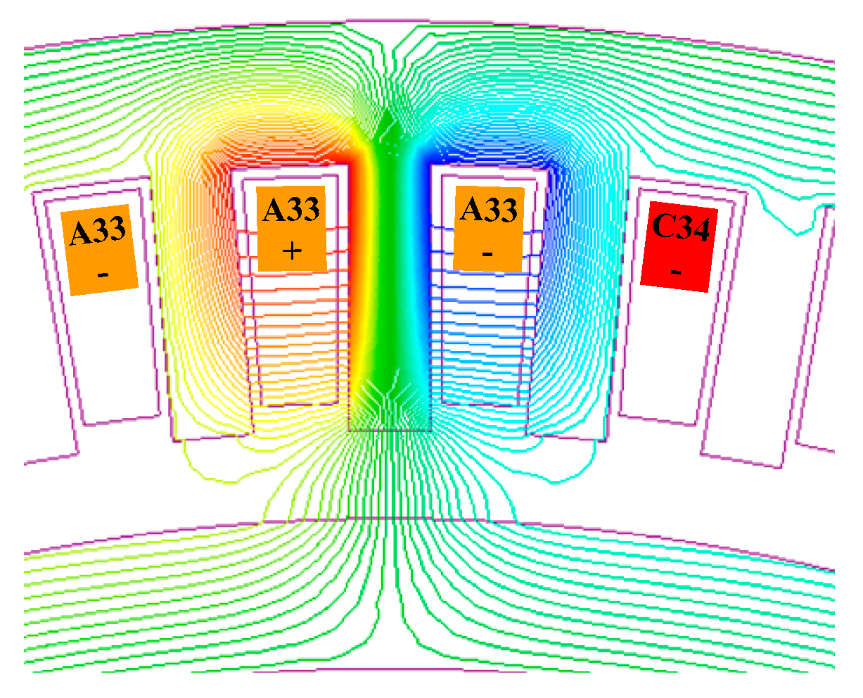
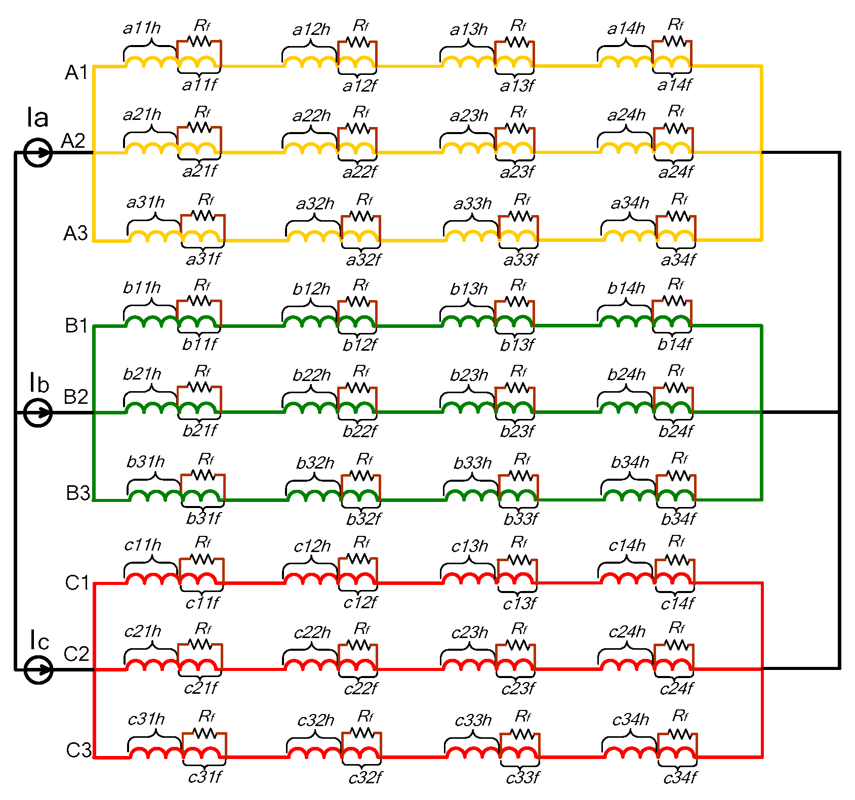
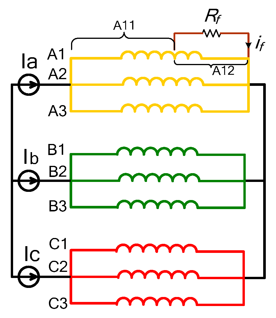
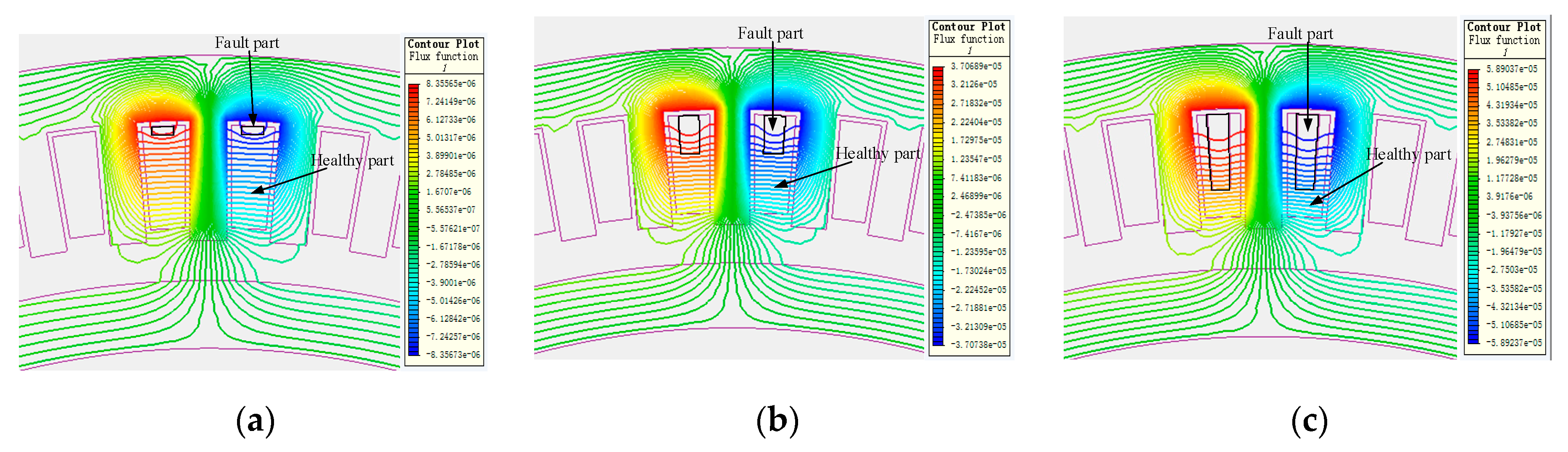
4. Model of DDPMSM with SWF

Figure 7 shows the stator circuit schematic with ITSCF in the A phase. It can be seen that fault branch A1 is divided into the healthy part A11 and the faulty part A12. Additionally, resistor R f , connected in parallel on the faulty coil, means the insulation fails between turns, where its value depends on the fault severity. When R f decreases toward zero, the insulation faults evolve toward an inter-turn full short-circuit. In this paper, the value of the value of R f is set to 0.4 Ω .
For establishing the analytical model of the DDPMSM with SWF, we assume that the magnetic permeability of iron is infinite and the magnetic saturation is not taken into account. Furthermore, the eddy current losses, hysteresis loss and higher harmonics are also negligible. Additionally, the ITSCF is represented using an additional circuit (subscript f), which increases the order of analytical model compared to the model in the healthy situation.
With the above assumptions and using the circuit scheme presented in Figure 7, the electrical equation of such model can be written as [14]:
v A B C f = R A B C f · i A B C f + L A B C f · d i A B C f d t + e A B C f
where:
{ i A B C f = [ i A 1     i A 2     i A 3     i B 1     i B 2     i B 3     i C 1     i C 2     i C 3     i f ] T v A B C f = [ v A 1     v A 2     v A 3     v B 1     v B 2     v B 3     v C 1     v C 2     v C 3     v f ] T e A B C f = [ e A 1     e A 2     e A 3     e B 1     e B 2     e B 3     e C 1     e C 2     e C 3     e f ] T
R A B C f = [ R A 1 0 0 0 R A 12 0 R A 2 0 0 0     0 0 0 R C 3 0 R A 12 0   0 0   R A 12 + R f ]
L A B C f [ L A 11 M A 2 A 11 M A 3 A 11 M C 3 A 11 ( M A 12 A 11 + L A 12 ) M A 11 A 2 L A 2 M A 3 A 2 M C 3 A 2 M A 12 A 2 M A 11 A 3 M A 2 A 3 L A 3 M C 3 A 3 M A 12 A 3 M A 11 C 2 M A 2 C 2 M A 3 C 2 M C 3 C 2 M A 12 C 2 M A 11 C 3 M A 2 C 3 M A 3 C 3 L C 3 M A 12 C 3 ( M A 12 A 11 + L A 12 ) M A 2 A 12 M A 3 A 12 M C 3 A 12 L A 12 ]
The stator windings in the healthy motor are supposed to be star connected; this implies that the zero sequence component of the stator current is zero [8]:
i A 1 + i A 2 + i A 3 + i B 1 + i B 2 + i B 3 + i C 1 + i C 2 + i C 3 = 0
where i f is the fault current, v f is the fault voltage, and e f denotes the fault back electromotive force. Generally, the value of v f is equal to 0.
Additionally, we have the following considerations: R j (j = A11, A12, A2, A3, B1, B2, B3, C1, C2, C3) is the resistance of the winding j. L j and M i j (i and j = A, B, C) are, respectively, the self and mutual inductances of the healthy motor. L j (j = A11, A12), M A 12 k (k = B, C, A2, A3), and M A 11 k (k = B, C, A12) are the self and mutual induction involving the fault circuit. R f and i f are the fault resistance and current, as shown in the Figure 7. If the healthy motor is balanced, we have:
R A 11 + R A 12 =   R A 1 =   R A 2 =   R A 3 =   R B 1 =   R B 2 =   R B 3 =   R C 1 =   R C 2 =   R C 3
L A 11 + L A 12 + 2 · M A 11 A 12 = L A 1 = L A 2 = L A 3 = L B 1 = L B 2 = L B 3 = L C 1 = L C 2 = L C 3
where, according to the value of μ , it can be obtained that R A 12 = μ R A 1 and R A 11 = ( 1 μ ) R A 1 [15].

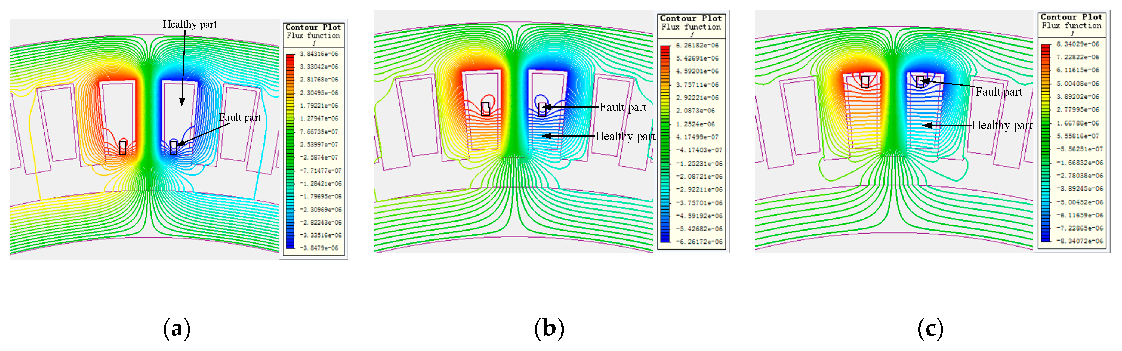
5. Validation of the Proposed Method by Comparing Inductance and Fault Current

To verify the theoretical investigations on the inductance calculations, we compare the obtained inductances with those provided by the FEM, NAM, and SAM for the same motor. In additions, the fault current is also studied by the proposed method, where the fault current is the most representative indicator for the motor with ITSCF.

5.1. Inductance Comparisons

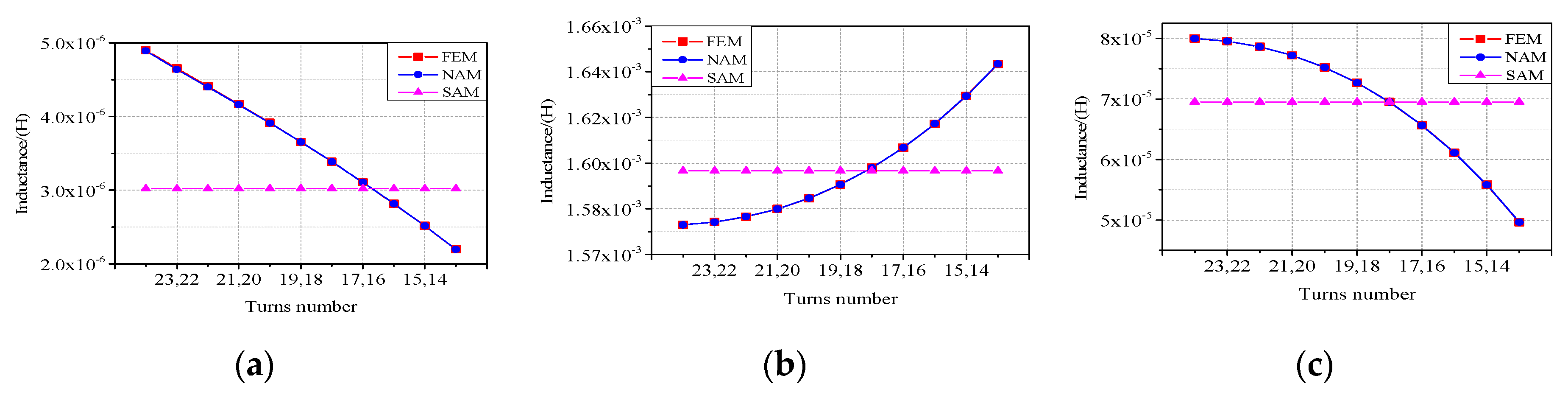
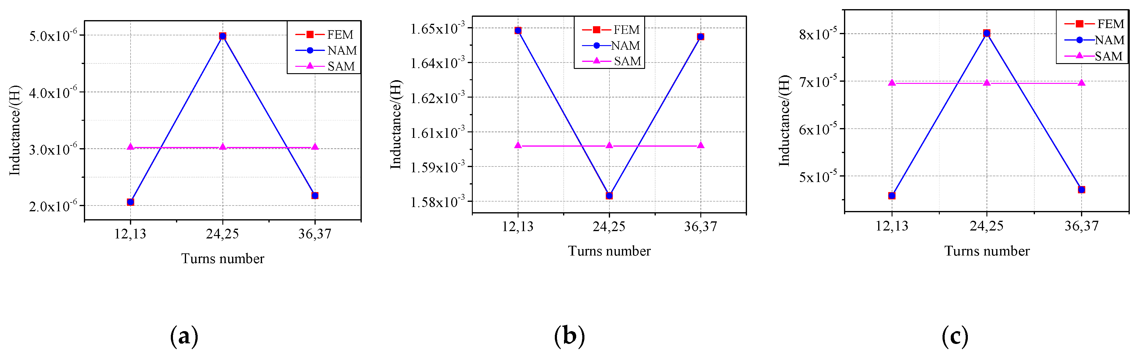
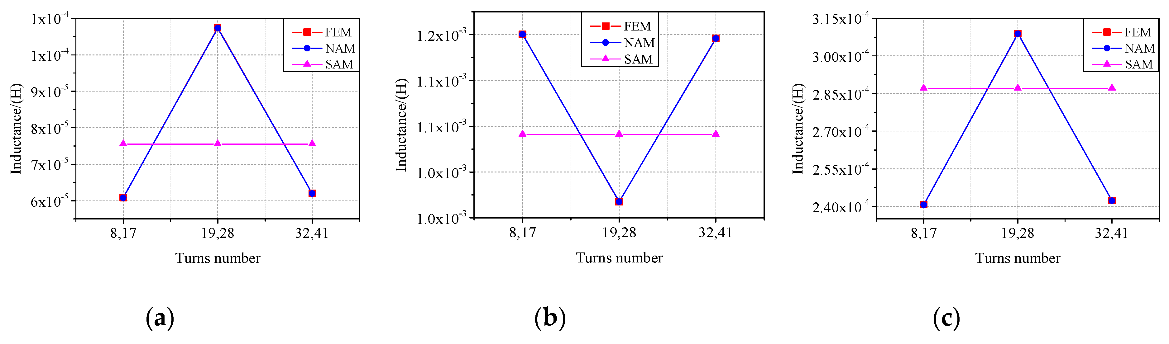
5.1.1. Inductances Identification of Faulty Coils in the Slot

ITSCF in the Same Layer

Table 2 shows the self-inductance of the faulty part in the finite-element model. It can be seen from Table 2 that the self-inductance of the faulty part is at a minimum when the faulty turns are located in layer 2 and the self-inductance of the faulty part are maximum when the faulty turns are located in layer 4. That is to say, when the same number of turns is short-circuited, the fault that occurred in layer 2 has the weakest effect on the motor performance. Therefore, different kinds of faults located on layer 2 are studied by using the NAM. Additionally, the results calculated by the FEM, NAM, and SAM are compared to verify the accuracy of the proposed method.
Figure 8 shows the flux density distributions when there are two turns shorted in layer 2 at the positions from the bottom of the slot to the slot opening. Figure 9 describes the flux density distributions when different numbers of turns are shorted in layer 2. It can be seen that all the flux density distributions mentioned above are different.
When the fault occurs on the same layer, the inductances of the faulty coil are shown in Figure 10, Figure 11 and Figure 12. Figure 10 analyzes the inductances of fault coil when there are two turns shorted in layer 2. Figure 11 describes the variation of the inductances in the faulty coil when there are six turns shorted in layer 2. And the inductances of fault coil, when there are 10 turns shorted in layer 2, are presented in Figure 12. It can be seen from Figure 10, Figure 11 and Figure 12 that, as the fault position changes from the bottom of the slot to the slot opening, the self-inductance of the faulty part gradually decreases while the self-inductance of the healthy part tends to increase, and the mutual inductance between the faulty and healthy parts gradually decreases. The comparisons among Figure 10, Figure 11 and Figure 12 reveals that, as the number of the shorted turns increased, the self-inductance of the faulty part is increased while the self-inductance of the healthy part tends to decrease, and the mutual inductance between the faulty and healthy parts gradually increases. Furthermore, Figure 10, Figure 11 and Figure 12 indicates that the error between the finite-element result and the result calculated by the NAM is smaller than one between the finite-element result and the result obtained by the simplified method. In addition, it is verified that the simplified inductance calculation method does not consider the spatial position.

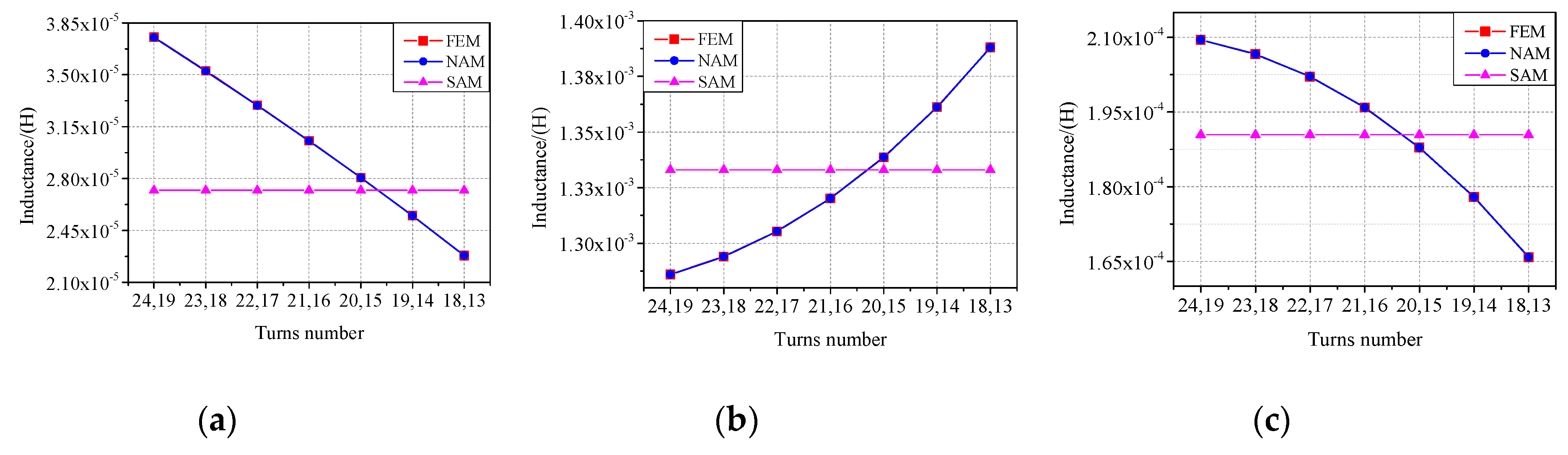
ITSCF in the Different Layers

Figure 13 compares the flux density distributions when the fault with different shorted turns is located on different layers. It can be seen that all the flux density distributions mentioned above are different.
When the fault occurs on different layers, the inductances of the faulty coil are as shown in Figure 14, Figure 15 and Figure 16. Figure 14 describes the inductance’s variation of the faulty coil when there are two turns shorted in different layers. Figure 15 compares the inductances of fault coil when there are 10 turns shorted in different layers. Additionally, as shown in Figure 16, the inductances of the faulty coil are analyzed when there are 18 turns shorted in different layers. In Figure 14, the turns of no. 12 and no. 13 belongs to layers 1 and 2, the turns of no. 24 and no. 25 are located in layers 2 and 3, and the turns of no. 36 and no. 37 are shorted in layer 3 and 4. Therefore, it can be found from Figure 11 that the inductances of the faulty coil are different when the fault turns are located in different layers. In addition, the inductances values of the faulty coil are related in the distance from the faulty part to the slot opening. The same conclusion can also be drawn from Figure 15 and Figure 16.

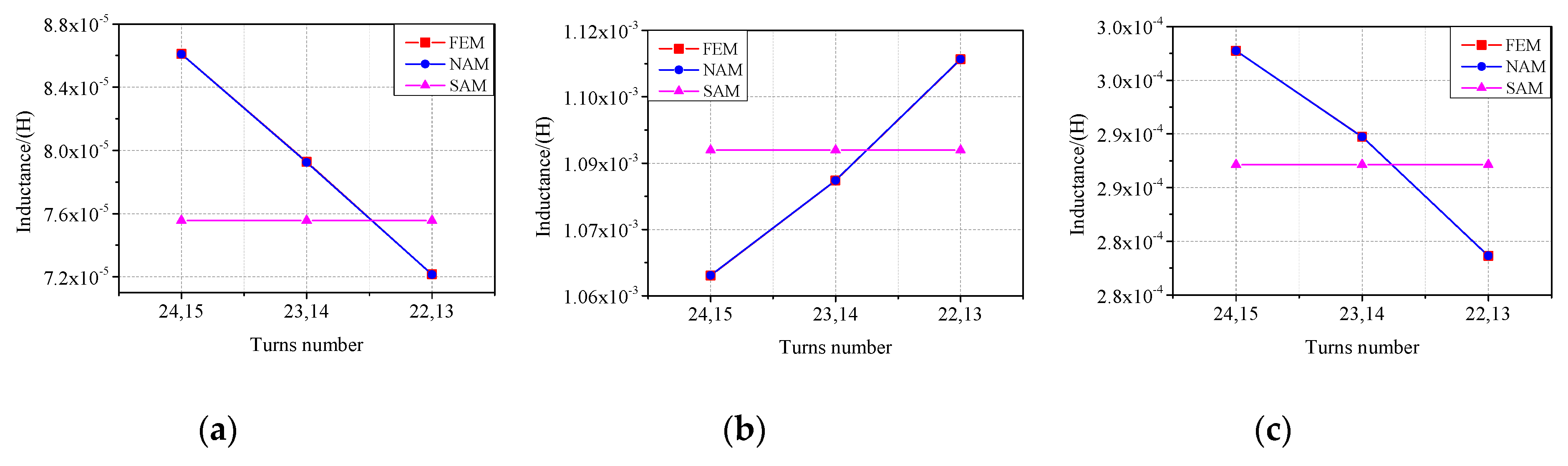
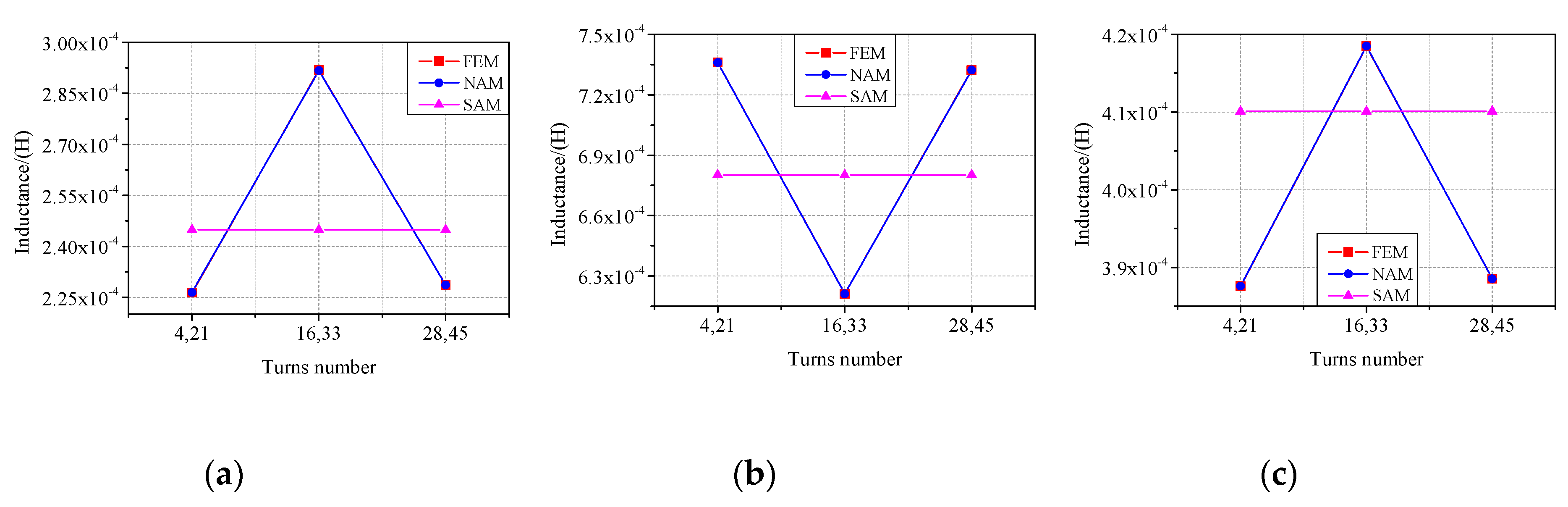
5.1.2. Inductances Identification of Fault Branches

When the fault occurs on branch A3 and there are six turns (X = 4–9) shorted in layer 2, all the branch inductances obtained by the FEM, NAM, and SAM are compared in Table 3. It can be seen that the branch inductances of the healthy part in faulty branch A3 as calculated by the FEM, NAM, and SAM are 0.006736H, 0.006736H, and 0.005033H, and the branch inductances of the faulty part in faulty branch A3 are 0.000227H, 0.000227H and 0.000022H. Error_1 in Table 3 analyzes the deviation between the results of FEM and NAM, and Error_2 indicates the error between the results of FEM and SAM. Table 3 shows that Error_1 is smaller than Error_2, which reveals that the results of NAM are in good agreement with the finite element results, and the accuracy of the NAM is higher than the SAM.

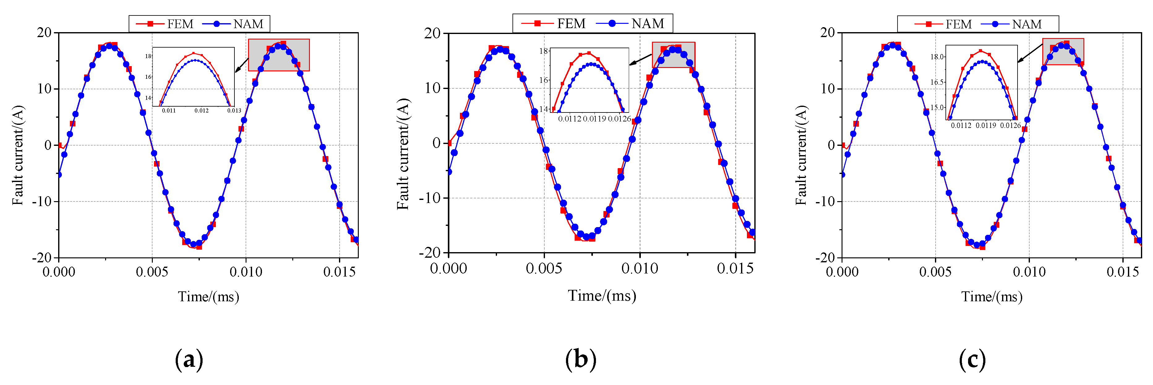
5.2. Fault Current Comparisons

Since the fault current i f , as shown in Figure 7, can reflect the fault severity, the fault current i f of the DDPMSM with SWF is studied in this section.

5.2.1. ITSCF in the Same Layer

When there are six turns shorted in layer 2 of the faulty coil, the waveforms of the fault current i f obtained by the FEM and NAM are as described in Figure 17. It can be seen from Figure 17a–c that the magnitudes of the fault current i f acquired by the NAM are 11.380A, 11.094A, and 11.017A, which indicates that the value of the fault current is reduced as the fault position changes from the bottom of the slot to the slot opening. When the shorted turns are the turns from no. 13 to no. 18, Figure 17a shows that the fault currents amplitude calculated by the FEM and NAM are 11.617A and 11.380A, respectively. Compared with the finite-element result, the fault currents calculated by NAM have decreased by 2.04%. Therefore, the magnitudes of the waveforms determined by the FEM and NAM have slight errors in their respective peaks and troughs.

5.2.2. Inter Turn Short Circuit Fault in the Different Layers

As shown in Figure 18, the fault current i f are analyzed the FEM and NAM, when there are 10 turns shorted in the different layers of the faulty coil. Figure 18a–c indicates that the frequency waveform obtained by the NAM is coincided properly with the ones obtained by the FEM with satisfactory accuracy. Figure 18a describes the fault current waveforms, when the shorted turns are the turns from no. 8 to no. 17, in which the value of fault current acquired by the FEM and NAM are 18.330A, 17.601A, and 16.486A, respectively. Compared with the finite-element result, the values obtained by the NAM have reduced by 3.97%. Therefore, the error between the results calculated by the FEM and NAM is within a reasonable range.

6. Conclusions

A NAM on the inductance identification method of DDPMSM with SWF is proposed herein, in which the spatial position of shorted turns in the ITSCF is considered. The inductance analytical expressions of the faulty coil are derived in detail. The accuracy of the proposed method is validated by the comparison with the results obtained by the FEM, NAM, and SAM.
Based on the proposed analytical method, the inductances of the faulty coil of the branch are calculated at different fault conditions and the fault current is also studied. The inductances and fault currents calculated by the NAM are compared with the ones obtained by the FEM and SAM, which shows that the accuracy of the proposed method is higher than that of the SAM. Additionally, it can be concluded that, as the fault position changes from the bottom of the slot to the slot opening, the self-inductance of the faulty part gradually decreases while the self-inductance of the healthy part tends to increase, the mutual inductance between the faulty and healthy parts gradually decreases and the fault current of the faulty coil is reduced.
The present work has laid an important foundation for the fault detection, modeling, and fault-tolerant control of the DDPMSM.

Author Contributions

Conceptualization: C.G.; data curation: M.G. and Y.H.; formal analysis: M.G.; funding acquisition: C.G. and J.S.; methodology: C.G., M.G., J.S., and Y.H.; resources: P.S.; software: M.G. and P.S.; writing–original draft: M.G.

Funding

This work is supported by the National Natural Science Foundation of China under grant no. 51777060 and no. 51277054, and the Key Science and Technology National Program of Henan Province, no. 192102210230.

Conflicts of Interest

The authors declare no conflict of interest.

References

  1. Tang, R.Y. Modern Permanent Magnet Machines Theory and Machines; China Machine Press: Beijing, China, 1997; pp. 310–311. [Google Scholar]
  2. Xia, C.L.; Ji, B.N.; Yan, Y. Smooth Speed Control for Low-Speed High-Torque Permanent–Magnet Synchronous Motor Using Proportional Integral Resonant Controller. IEEE Trans. Ind. Electron. 2015, 62, 2123–2134. [Google Scholar] [CrossRef]
  3. Donato, G.D.; Capponi, F.G.; Borocci, G. Ω-shaped axial-flux permanent-magnet machine for direct-drive applications with constrained shaft height. IEEE Trans. Ind. Appl. 2015, 51, 3050–3058. [Google Scholar] [CrossRef]
  4. Choi, G.; Jahns, T.M. PM Synchronous Machine Drive Response to Asymmetrical Short-Circuit Faults. IEEE Trans. Ind. Appl. 2016, 52, 2167–2185. [Google Scholar] [CrossRef]
  5. Vaseghi, B.; Nahid-mobarakh, B.; Takorabet, N. Inductance Identification and Study of PM Motor with Winding Turn Short Circuit Fault. IEEE Trans. Magn. 2011, 47, 978–981. [Google Scholar] [CrossRef]
  6. Bi, D.Q.; Wang, X.H.; Wang, W.J. Improved Transient Simulation of Salient-Pole Synchronous Generators with Internal and Ground Faults in the Stator Winding. IEEE Trans. Energy Convers. 2005, 20, 128–134. [Google Scholar] [CrossRef]
  7. Sim, J.H.; Ahn, D.G.; Kim, D.Y. Three-Dimensional Equivalent Magnetic Circuit Network Method for Precise and Fast Analysis of PM-Assisted Claw-Pole Synchronous Motor. IEEE Trans. Ind. Appl. 2018, 54, 160–171. [Google Scholar] [CrossRef]
  8. Leboeuf, N.; Boileau, T.; Nahid-Mobarakeh, B. Inductance Calculations in Permanent-Magnet Motors under Fault Conditions. IEEE Trans. Magn. 2012, 48, 2605–2616. [Google Scholar] [CrossRef]
  9. Gao, Y.T.; Qu, R.H.; Li, D.W. Improved hybrid method to calculate inductances of permanent magnet synchronous machines with skewed stators based on winding function theory. Chin. J. Electr. Eng. 2016, 2, 52–61. [Google Scholar]
  10. Xu, W.; Sun, G.Y.; Wen, G.L. Equivalent Circuit Derivation and Performance Analysis of a Single-Sided Linear Induction Motor Based on the Winding Function Theory. IEEE Trans. Veh. Technol. 2012, 61, 1515–1525. [Google Scholar] [CrossRef]
  11. Vaseghi, B.; Takorabet, N.; Meibody-Tabar, F. Fault Analysis and Parameter Identification of Permanent-Magnet Motors by the Finite-Element Method. IEEE Trans. Magn. 2009, 45, 3290–3295. [Google Scholar] [CrossRef]
  12. Mohammed, O.A.; Liu, Z.; Liu, S. Internal Short Circuit Fault Diagnosis for PM Machines Using FE-Based Phase Variable Model and Wavelets Analysis. IEEE Trans. Magn. 2007, 43, 1729–1732. [Google Scholar] [CrossRef]
  13. Vaseghi, B.; Takorabet, N.; Meibody-Tabar, F. Analytical circuit-based model of PMSM under stator inter-turn short-circuit fault validated by time-stepping finite element analysis. In Proceedings of the XIX International Conference on Electrical Machines—ICEM 2010, Rome, Italy, 6–8 September 2010. [Google Scholar]
  14. Leboeuf, N.; Boileau, T.; Nahid-Mobarakeh, B. Estimating Permanent-Magnet Motor Parameters under Inter-Turn Fault Conditions. IEEE Trans. Magn. 2012, 48, 963–966. [Google Scholar] [CrossRef]
  15. HÄRSJÖ, J. Modeling and Analysis of PMSM with Turn-To-Turn Fault. Ph.D. Thesis, Chalmers University of Technology, Göteborg, Sweden, 2016. [Google Scholar]
Figure 1. The structure of the DDPMSM: (a) overall structure; (b) local enlarged view.
Applsci 09 03599 g001
Figure 2. The armature flux linkage of A34.
Applsci 09 03599 g002
Figure 3. The distribution of the turns in the slot.
Applsci 09 03599 g003
Figure 4. Turn distribution when the inter-layer fault occurs at (W = 2, Y = 5).
Applsci 09 03599 g004
Figure 5. Turn distribution when the inter-layer fault occurs at (X1 = 2, Y1 = 5) to (X2 = 2, Y1 = 7).
Applsci 09 03599 g005
Figure 6. The stator circuit schematic with ITSF in multiple branches.
Applsci 09 03599 g006
Figure 7. The stator circuit schematic with ITSF in the A phase.
Applsci 09 03599 g007
Figure 8. The flux density distributions when there are two turns shorted in layer 2: (a) no. 13, 14; (b) no. 18, 19; (c) no. 23, 24.
Applsci 09 03599 g008
Figure 9. The flux density distributions when different numbers of turns are shorted in layer 2: (a) two turns shorted; (b) six turns shorted; (c) 10 turns shorted.
Applsci 09 03599 g009
Figure 10. The inductances of the faulty coil when there are two turns shorted in layer 2: (a) self-inductance in faulty part; (b) self-inductance in healthy part; (c) mutual inductance.
Applsci 09 03599 g010
Figure 11. The inductances of the faulty coil when there are six turns shorted in layer 2: (a) self-inductance in faulty part; (b) self-inductance in healthy part; (c) mutual inductance.
Applsci 09 03599 g011
Figure 12. The inductances of the faulty coil when there are 10 turns shorted in layer 2: (a) self-inductance in faulty part; (b) self-inductance in healthy part; (c) mutual inductance.
Applsci 09 03599 g012
Figure 13. The flux density distributions when the fault with different shorted turns is located on different layers: (a) two turns shorted in layers 2 and 3; (b) six turns shorted in layers 2 and 3; (c) 10 turns shorted in layers 2 and 3.
Applsci 09 03599 g013
Figure 14. The inductances of the faulty coil when there are two turns shorted in different layers: (a) self-inductance in faulty part; (b) self-inductance in healthy part; (c) mutual inductance.
Applsci 09 03599 g014
Figure 15. The inductances of the faulty coil when there are 10 turns shorted in different layers: (a) self-inductance in faulty part; (b) self-inductance in healthy part; (c) mutual inductance.
Applsci 09 03599 g015
Figure 16. The inductances of the faulty coil when there are 18 turns shorted in different layers: (a) self-inductance in faulty part; (b) self-inductance in healthy part; (c) mutual inductance.
Applsci 09 03599 g016
Figure 17. The waveforms of the fault current i f when there are six turns shorted in layer 2 of the faulty coil: (a) the shorted turns are the turns from no. 13 to no. 18; (b) the shorted turns are the turns from no. 16 to no. 21; (c) the shorted turns are the turns from no. 19 to no. 24.
Applsci 09 03599 g017
Figure 18. The waveforms of the fault current i f when there are 10 turns shorted in the different layers of the faulty coil: (a) the shorted turns are the turns from no. 8 to no. 17; (b) the shorted turns are the turns from no. 19 to no. 28; (c) the shorted turns are the turns from no. 32 to no. 41.
Applsci 09 03599 g018
Table 1. The main parameters of the DDPMSM.
Items (Unit)ValueItems (Unit)Value
Out diameter of stator (mm)360Axial length (mm)150
Inner diameter of stator (mm)300Rated power (kW)10
Inner diameter of rotor (mm)265Rated speed (rpm)200
Air-gap length (mm)1.2Number of phases3
Wire diameter of winding (mm)1.3Number of coils36
Area of slot (mm2)154Coil turns48
Thickness of PM (mm)5.3Parallel-circuits per phase3
Pole-arc coefficient0.83Slot-pole combination72–66
Table 2. The self-inductance of the faulty part in the finite element model.
Turns2 Turns (Y = 1–2)6 Turns (Y = 1–6)10 Turns (Y = 1–10)
Layer
Layer15.07339 × 10−63.842 × 10−58.76368 × 10−5
Layer24.89856 × 10−63.7532 × 10−58.6111 × 10−5
Layer34.89909 × 10−63.75409 × 10−58.62187 × 10−5
Layer45.07488 × 10−63.84441 × 10−58.79202 × 10−5
Table 3. The comparison of branch inductances when there are six turns shorted in branch A3.
MethodFEMNAMError_1SAMError_2
Branch
A10.0069610.0069623.08822 × 10−50.00696−0.00024
A20.0069620.0069626.95848 × 10−60.006961−0.00013
A3_healthy0.0067360.006736 2.84437 × 10−50.005033−0.25275
A3_fault0.0002270.000227 4.2603 × 10−72.2 × 10−5−0.90304
B10.0069760.006976−4.12819 × 10−80.0069780.000282
B20.0069780.006978−5.6927 × 10−60.0069790.00014
B30.0069760.006976−1.44934 × 10−60.006971−0.00065
C10.0069750.006975−4.33412 × 10−70.0069760.000212
C20.0069760.006976−5.9959 × 10−70.0069770.000129
C30.0069760.0069762.41647 × 10−60.006972−0.00062

