Abstract
Recently, the approach that defines the total life cycle assessment (LCA) and the end of life (EoL) in the early design phases is becoming even more promising. Literature evidences many advantages in terms of the saving of costs and time and in the fluent organization of the whole design process. Design for disassembly (DfD) offers the possibility of reducing the time and cost of disassembling a product and accounts for the reusing of parts and of the dismantling of parts, joints, and materials. The sequence of disassembly is the ordered way to extract parts from an assembly and is a focal item in DfD because it can deeply influence times and operations. In this paper, some disassembly sequences are evaluated, and among them, two methods for defining an optimal sequence are provided and tested on a case study of a mechanical assembly. A further sequence of disassembly is provided by the authors based on experience and personal knowledge. All three are analyzed by the disassembly order graph (DOG) approach and compared. The operations evaluated have been converted in time using time measurement units (TMUs). As result, the best sequence has been highlighted in order to define a structured and efficient disassembly.
1. Introduction
The concept of design for assembly is now rooted and consolidated within industrial activity, gaining important benefits regarding the production costs of various products, from mechanics to electronics; these policies also allow for a rational use of production environments and improve the working conditions of operators. With the relentless technological progress, the volume of goods produced has increased exponentially, and consequently, a reduction in the useful life due to the obsolescence of the systems (above all in the field of electronics); this has led to the increase of waste and old machinery that can become a potential risk for the environment. As a result, policies have been implemented for the proper disposal of this waste through the dismantling of various disused devices; however, this activity can potentially become disadvantageous when dismantling is difficult to implement due to difficult to manage materials and design choices totally aimed at optimizing production. Many optimization methods based on QFD (quality functional deployment), TRIZ (theory of inventive problem solving), and benchmarking can support the product design from the early phases onward [1,2,3,4]. They try to convert the user’s requirements into product specifications and they are useful instruments for competitive analysis and continuous improvement [5]. Chen adopted [6], for example, an innovative design methodology based on TRIZ is proposed that uses active disassembly technology as fasteners made using shape memory plastics in order to achieve an easy dismantling of parts. Sakao [7] adopted LCA, an extension of QFD (QFDE—quality function deployment for environment) and TRIZ in order to reduce the energy consumption of a hair drier. The methodology suggests to designers to be aware of the product’s high impact on global warming through energy consumption during its use phase, which is one of the LCA results, to define a requirement objectively in QFDE, i.e., “reduce the energy consumption” with a high weighting. The QFDE result was that “dry quickly” and “dry quietly” have a contradiction. For this contradiction, the implementation of TRIZ suggested four improvement solutions, and among them, the best one was chosen. Fargnoli et al. [8] presented an application of QFD to many ambits of Design for Disassembly (DfD). Many houses of quality were proposed (safety function deployment, quality function deployment for environment, quality function deployment for maintenance, green quality function deployment, QFD for product/service system), and they were tested on a common case study, confirming the success of the house of quality theory.
All these optimization applications give advantages toward finding the best solution to issues concerning the product development; design for disassembly (DfD) puts the attention, already in the preliminary design phase, to the EoL (end of life) cycle of the product, which involves implementing choices that allow for an effective dismantling and minimizing of waste, thus exploiting the potential re-use of parts and materials obtained after the disassembly. The main factors influencing the ease of disassembly of products are the financial aspects, including the costs of the disassembly process, the cost of benefits of the item reuse, and the recycling costs of disposal and environmental impact. These aspects reflect on the improvement of the environmental performance of re-manufacturing and recycling activities. A method suggested by Harjula [9] shows how the disassembly sequence can influence financial benefits, even if the environmental implications have to be taken into account. DfD can be intended toward three areas: selection of materials, design of components and layout of products, and careful selection of fixing and connection systems. Assembly and disassembly plants can be optimized [10,11,12] and disassembly operations can be mechanized, also with the help of digital/augmented reality tools [13]. It is essential to notice that DfD is not simply the inverse of the design for assembly, but a trade-off between the production cycle and the recycling cycle that leads to an optimization of both costs and maintenance during the life of the mechanism.
2. State of the Art
Many attempts have been made in the literature toward products’ disassembly planning. They mainly focus on the definition of strategies that can guide the designer toward a quantitative evaluation of disassembly ease for products. In Reference [14], the disassembly plant of a computer power unit (CPU) has been analyzed in order to validate a method based on the filling of an evaluation chart that described the disassembly process by means of some entries such as the quantity, the task types and repetitions, the required tools to disassemble parts, and the difficulty rating of the disassembly process. Finally, it evaluated the ease of disassembly in terms of the design effectiveness and the disassembly time.
Integrating the principles and ideas of the DfD is useful for verifying the disassembly cycle while the component still needs to be produced by exploiting the virtual environment. Computer simulation is a powerful method for designing and analyzing manufacturing processes in industry [15], for operations management [16], or just in the disassembly process organization [17]. As described by Osti [18], during ESD (early stage design), the best configuration should be sought to make the product more sustainable throughout its life cycle. The study of these needs through the study of the Computer Aided Design (CAD) model remains effective. In this paper, we started from the CAD model of a gearbox in order to analyze its disassembly sequence. It was found that CAD models did not highlight the problems related to the physical interactions between the component and the operator.
The disassembly sequence is an essential step for product disassembly because it influences the productivity and the costs. Other approaches use a geometrical reasoning technique to establish this precedence knowledge. However, there are cases that cannot be solved using geometric reasoning alone. Although the geometric reasoning technique has weaknesses, the approach has the advantage of achieving integration with CAD models.
These approaches can detect interference directly from the 3D representation of a CAD model. However, higher accuracy of the result increases the cost of the computation. Using CAD, product disassembly can be carried out visually on a computer, so it is easier to generate an optimal disassembly sequence and to establish a correct and practical disassembly path for the part in the product. The product disassembly time depends on several factors such as component shape, size and weight, joining element, joining direction, disassembly tools, and equipment [19]. In the literature, different classifications have been proposed for mechanical connections and part interfaces [20,21]. Mandolini [22] proposed a structured method for analytically estimating the disassembly time in a complex assembly. They defined a repository (called Liaison_DB) containing the essential time base data of the main assembly liaisons and corrective factors that are used for the disassembly time estimation for calculation of the effective disassembly time.
Even if the proposed classifications can be considered to be the basis for the development of a complete characterization of assembly/disassembly liaisons, they have some limitations as they are not complete and do not propose an effective disassembly time for each category or item, and they are based on a theoretical framework and not on experimental analyses.
As is well known, the number of possible disassembly sequences significantly increases with the number of parts in a product. Thus, the generation of proper disassembly sequences order is critical. Good attempts to define methods that could help the designer achieve DfD optimization have been presented by Cappelli [23]. The main issue concerns the complexity of mechanical assemblies that require high computational resources to be solved. The cited method proposed, despite introducing a very good methodology to find an optimal sequence of disassembly, is applied to a very simple subassembly. The application of such a method to a complex assembly does not provide the same optimal results, in terms of computational times, as most of the existing methods often require expensive computational resources while, at the same time, they often fail to find optimal solutions for complex product disassembly. However, the available disassembly evaluation methods today seldom make disassembly the preferred end-of-life solution for the reuse of parts or components in an economically sustainable way for lower value products. DfD has become a challenging problem for the automotive industry because it has been estimated that 75% of the weight of each vehicle disposed of can be recovered. Nowadays BMW is a leader in the dismantling and recovery of parts, and great interest from the market is addressed toward the dismantling of the gearbox [5].
A general classification for disassembly methods can be made as follows:
- Interactive methods for the sequence generation that get information from the users. They can become unrealistic when the disassembly operator is not the designer of the product [24,25].
- Automatic methods are preferred way for sequences generation. This allows one to generate the disassembly sequences automatically, according to the geometry relationship among the components in a product. However, how to find the easiest and simplest model for sequence generation in an automatic way is still an issue [26,27,28,29,30,31,32,33].
- Searching algorithms, based on heuristic searching, wave propagation approach, and Dijkstra’s algorithm [34,35,36,37,38], have high computational complexity [39].
- Artificial intelligence methods try to find the optimized way for sequence generation relating to the expert system or online calculations for real applications in industries and need relatively long execution times for sequence searching [40,41,42].
Exploiting mixed and augmented reality (AR) technologies enables one to deal with both design for assembly and DfD by performing assembly/disassembly simulations and the training of operators who will then perform the established operations, despite the use of digital mock-up (DMU) models for assembly/disassembly evaluation, which has limited application areas because of its high cost investment. Advantages from the use of AR within the industrial sector are several: reduction of the risk of accidents in dangerous operations; reduction of the cycles of development; reduction of human error in the execution of the operations; improvement of efficiency, and reduction of time and costs related to the maintenance, production, and disposal of products [43,44].
However, a further integration of the current analysis with VR tools will be implemented using a system equipped with an HMD (head mounted device) [45], on which the step-by-step instructions are displayed and can be implemented with the operator’s knowledge in a virtual environment.
3. A Virtual Gearbox as a Disassembly Case Study
Disassembly sequence planning consists of the realization of a disassembly sequence coherent with the benefits that DfD can offer. Villalba et al. [46] utilized the important aspects of DfD. For Zhou [47], the main existing disassembly sequence planning methods from the perspectives of disassembly mode, disassembly modelling, and planning method have been reviewed; the characteristics of different methods have been analyzed; and future trends in disassembly sequence planning are discussed.
In order to reduce the time and cost of disassembling a product and to optimize the reuse of parts and different materials, this paper discusses the evaluation of an optimal disassembly sequence to be performed on a case study. The method is developed and discussed in the context of relatively small products that can be disassembled by a seated person using hand-held tools. The market has recently demonstrated great interest in the dismantling and recovery of parts in the automotive industry, and in particular, in the dismantling of gearboxes.
This helped us to choose the product under evaluation, which is an orthogonal axis speed gearbox from the Rossi Motoriduttori Soc. of Modena (Figure 1), whose bill of materials (BOM) is shown in Table 1.
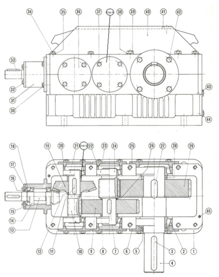
Figure 1.
Technical 2D drawing of the orthogonal axis speed gearbox.

Table 1.
The Bill of Material of the speed gearbox.
The speed gearbox was reproduced from the original 2D drawings in a 3D environment using CAD by employing the CREO PARAMETRIC 3.0 software, developed by PTC—Parametric Technology Corporation, Needham, USA, which is a parametric 3D modeler that is quite intuitive and specifically created for mechanical engineering.
The gearbox was disassembled by following three different sequences. Two of these have been suggested by References [48,49], while the third has been proposed by the current authors, which were guided by personal knowledge and experience.
In the assembly environment, the virtual gearbox has been modelled by taking into account all the functionality of the components. Given the number of components, the total assembly has been subdivided into four sub-groups, represented in Figure 2 that enables for the data to be managed in a more accessible way.
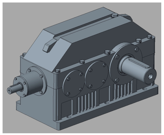
Figure 2.
The total assembly of the gearbox.
The four sub-groups correspond to the four shaft sections, parts of the transmission of the motion. One of this sub-groups is shown in Figure 3 for convenience.
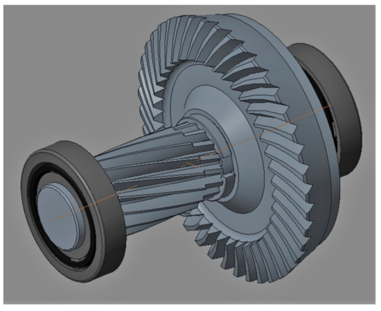
Figure 3.
One of the four subgroups composed of a shaft, gears, and bearings.
The assembly refers to the first part inserted into the ambient that is the box. The four sub-groups were inserted starting from the output shaft, going up to the pinion, which was entry of the motion. The groups were assembled so that the bearings are aligned with their seats, made in two components. During the assembly arrangement, eventual errors accumulated along the measurement phase and the conversions through the scale factor were checked. During the assembly operations, it was necessary to pay attention to the correct alignment of the wheels, a determining factor for their correct functioning. Before “closing” the gearbox, two plugs were inserted (placed at the two ends of the support surface) such that they can act as a centering for the aligned installation of the cover with respect to the casing. Finally, the lock washers were inserted and then the screws that clench onto the casing were tightened to the correct torque. A complete assembly of the gearbox is shown in Figure 2. Once the assembly was completed, the disassembly evaluation could start.
4. The Disassembly Sequences for Evaluating the Disassembly Efficiency of the Virtual Gearbox
The optimal sequence of disassembly has been investigated by seeking the best compromise between the time taken for disassembly and the operations performed. This subject matter is the object of the attention of many teachers/technicians because it is essential to find an optimal working cycle for two reasons: the dismantling of the device and its maintenance. The first is devoted to an eco-friendly perspective, since it tries to limit the environmental impact of industrial operations, while the second is oriented toward the limitation of management costs by reducing the time for ordinary and/or extraordinary maintenance. In searching for the optimal sequence for this case study, three different paths have been compared in order to grasp the differences in their modus operandi and to understand how these methods interact with the work environment and with the geometry of the component.
4.1. DfD Sequence Proposed by the Current Authors
The sequence developed by the current authors was derived from the observation of the 3D model and from how to remove the gearbox. Four subgroups of the assembly were considered as a whole block and their sequence was calculated separately and then integrated into the optimized sequence. The four groups, shown in Figure 4, were made of components numbered as follows:
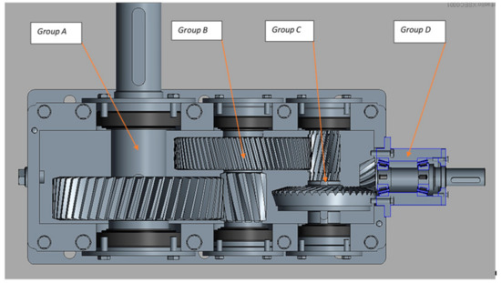
Figure 4.
The four sub-groups of the gearbox.
Group A: 3-2-28-29-27-2-4 (referred to in the text as grA);
Group B: 23-8-9-7-26-23-24 (referred to in the text as grB);
Group C: 21-13-19-11-12-21-10 (referred to in the text as grC);
Group D: 33-32-16-15-17-18-14-13-31 (referred to in the text as grD).
In the list of the above groups, the elements have already been indicated in the order in which they must be disassembled.
The sequence developed tries to reproduce how to disassemble the gearbox and is described as follows: start by removing all the external components of the gearbox, such as the tongues of the connecting shafts, then the group consisting of the shaft from the incoming pinion with its relative support. Then, proceed with the removal of the intermediate shaft covers (and related screws), followed by the oil seal of the output shaft and the output shaft covers. Once the cover is free, proceed by loosening the clamping screws (M12 and M14) and then removing the cover, taking care not to damage the two pins that act as guides. Then, remove the pins and the bearing spacers. Focus on the various sub-groups, starting from group C (i.e., the one containing the crown gear) and then its disassembly. Remove the bearing, then the spacer between the inner ring and toothed wheel, then remove the toothed wheel and the relative tongue for the transmission of the motion. Conclude the group C removal by removing the opposite bearing and the relative spacer. Proceed to remove subgroup B, i.e., the intermediate shaft for the cylindrical gears. The procedure follows that used for the previous sub-group: remove the bearing with diameter 50, the spacer between inner ring and wheel, the cylindrical toothed wheel with the relative key, and finally, the spacer between the wheel and the shoulder. For the opposite side, it remains to remove the second bearing that directly supports the pinion. Then, follow with the removal of group A, the one containing the output tree, which is disassembled by a process very similar to that used for the other two groups.
The disassembly of the input shaft group remains to be addressed, which requires some precautions given its particular structure. Always starting from the external elements, remove the oil seal and the relative cover (including the screws that bind it). Remove the elastic ring that binds the bearing and then the spacer ring. The “O” configuration of the two bearings makes the disassembly difficult, but with the aid of a press and a perforated support (such that the pinion passes inside), it is possible to first remove the bearing on the lid side, then to easily disassemble the gearing side bearing. The last detail that can be defined as necessary activity is the removal of the top-up and oil drain plugs.
The final sequence for the disassembly is detailed below:
3-33-30-37-36-copA-5-42-6-25-34-39-35-38-39-40-45-20-22-grC-21-distB-19-11-12-
21-10-grB-23-8-9-7-26-23-24-grA-2-28-29-27-2-4-16-32-15-17-18-14-13-14-31-41-43-44
4.2. DfD Sequence Proposed by the Jianjun’s Method
This first sequence is the result of the algorithm illustrated by Jianjun [48] and is based on the concept of “disassembling waves.” It consists of considering the component to be reached during the disassembly as the origin of a wave that propagates to touch, in all directions, the elements in contact with the target element; then, the wave is propagated further by touching the elements that are in contact with the elements previously interacted with. A necessary preliminary element is a complete and in-depth knowledge of the elements that make up the mechanism and how they are in contact with each other; for this purpose, the authors went on to define two types of components: the “d-dependent” and “1-dependent” components. A “d-dependent” component is an element that is in contact simultaneously with n elements: in order to break it up, the n elements have to be removed beforehand to access it. Otherwise, a 1-dependent element is an element that only needs the removal of one of the elements with which it is in contact to access it. In light of this classification and of the concept underlying the algorithm, it is possible to build the “removal influence graph” (RG) that is the representation of the “disassembly wave.” Indicating with a circle and a number the target element, all the elements that have been hit by the wave at the first moment have been arranged around this element, and in order to reflect the directions in which they are mounted, an arrow is used to connect them. Starting from the elements found on the wave at the time t, the wave has to propagate by intercepting the elements in contact with it. The process is repeated until all the components have been reached. Once the RG has been generated, it is necessary to find the disassembling sequence by tracking down the path that leads from the outermost level to the desired component, always respecting the respective rules for “d-dependent” and “1-dependent” components. Briefly, the method presents the disadvantage of understanding the enigmatic basic principle and the necessity for a deep knowledge about the mechanism, but on the other hand, this is compensated for with an ease of application and a good versatility.
Using a contextualization of this method toward the proposed case study, it has been applied to the three groups of trees, and from here, the sequence for total disassembly has been deduced. By placing the wave source as single tree, the RG became uselessly rich at moments and too articulated to exploit the immediacy of the method; alternatively, by applying the method to the three subgroups, three RGs were obtained that could be connected to each other, creating a map of easy interpretation. They are shown in Figure 5, Figure 6 and Figure 7.
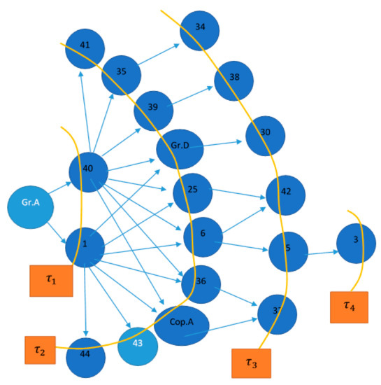
Figure 5.
The RG that enables the disassembly of group A.
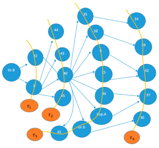
Figure 6.
The RG that enables the disassembly of group B.
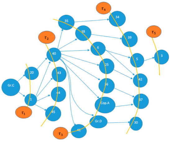
Figure 7.
The RG that enables the disassembly of group C.
The various subgroups were then disassembled with the sequence previously mentioned given by the geometry of the system. The sequence obtained following this process is:
3-34-39-5-37-30-42-35-38-6-25-36-copA-grD-41-40-45-43-44-20-22-grC-21-distB-19-
11-12-21-10-grB-23-8-9-7-26-23-24-grA-2-28-29-27-2-4-33-16-32-15-17-18-14-13-14-31
4.3. DfD Sequence Proposed by the Mitrouchev et al.’s Method
The second sequence was obtained by the application of the method proposed by Mitrouchev [49]. It performs a very accurate study, both on the structure and spatial configuration of the elements creating the sequence through two instruments: the first is the DGCG (disassembly geometry contacting graph) and the second is the DOG (disassembly order graph). For the construction of the DGCG, a careful study of the structure of the gearbox is necessary through the search for “geometric feasibility,” the “Set of Directional Removal (i.e., SDR),” and the “collision detection.” “Geometric feasibility” refers to two elements that can be assembled/disassembled so as not to create interference/collisions between them; the knowledge about these properties allows one probe the directions in which to disassemble the connected elements. The “SDR” refers to all the directions in which the component can be disassembled based on the functional surfaces of the component. As far as the screws and the connecting parts are concerned, only one SDR was proposed in order to simplify and optimize the calculation (in the case of software coding). In order to find the SDRs of two elements, it is important to notice whether their projection on a plane creates some overlaps that can indicate a potential impact between the objects in 3D. After reading the publication, the current authors conclude that if a component cannot be disassembled, it may be because SDRs are not available or because there are collisions in the projection in that direction. Following these introductory concepts, the DGCG was created for the gearbox, which describes the contacts and the configuration of the elements. It is shown in Figure 8.
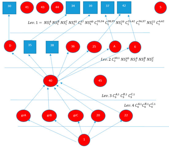
Figure 8.
The DGCG used to analyze the levels.
Various “disassembly levels” are defined in the diagram of Figure 8 by ordering the elements according to their accessibility. On the first level are all those elements that can be removed directly without going to touch other elements. Regarding these elements, the possibility of collisions or absence of SDR was checked. Then, it was possible to proceed by removing the elements on the second level, which are all those parts able to be accessed after the dismantling of the first level. Once again, the possible collisions and the SDR were checked. This process repeats until the lowest level was reached, so it was possible to connect the elements in contact with each other by arrows so as to have a complete view of the system’s scheme. Once the mechanism was explicated, there were some small rules to respect to build the graph: the elements were indicated using a circle while the connecting elements indicated with a square. Here, the notation to indicate the collisions and the absence of SDR is introduced:
- If the ith component cannot be disassembled at this nth level for a collision with the jth element, it is indicated as.
- If there are no disassembly directions at the nth level for the ith component, it is indicated as.
Therefore, the DOG can be defined by arranging the various elements following the levels previously obtained, starting from the target component, which forms the base. Then the subgroups could be disassembled since they cannot be the object of optimization. The elements were connected together to represent the possible paths for the component disassembly. By observing the two classifications made before, it was possible to find the path that led to the desired element. The procedure was the following: from the external level, enter the previous level, identifying the component that allows access to the next level, then remove all the elements that surround it and finally the element that brings it to the next level.
The RG to generate the sequence created and it is shown in Figure 9.
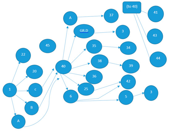
Figure 9.
The RG created to generate the sequence.
This procedure was repeated until the destination level was reached. By following this working method, the desired sequence is:
3-41-43-44-34-39-30-37-42-5-6-25-copA-36-grD-35-38-40-45-20-22-grA-grB-grC-1-
2-28-29-27-4-23-8-9-7-26-23-24-21-disB-19-11-12-21-10-33-16-32-15-17-18-14-13-14-31
A tentative hypothesis can be formed stating that this sequence is better than the previous one because a better care in the research is observed through the analysis of the contacts of the functional surfaces and the connecting elements.
5. A Quantitative Evaluation of Sequences and Time
Having reached the end of the search for the disassembly sequence, the three sequences found have been checked in order to decide upon the optimal sequence in terms of savings of time. The calculation of times, referring to the disassembling of the gearbox, has been made using TMUs due to the unavailability of the gearbox that was only a CAD model. The environment with tools has been hypothesized too, compatibly with a credible production environment. These assumptions have been made according to References [50,51] that allow for an estimate of the disassembly time through a process of assigning points to then be converted into seconds.
Desai [50] considers DfD to optimize the workings and the interaction of the operator with the process, being the aim of the project activity. The resulting life cycle of the product is already influenced during the first design phases, defining structure, and components. In this phase, if a careful choice of the elements and a homogenization of the parts are adopted, 10–20% of gain on the following EOL cycle of the product or on the maintenance phase can be obtained. After the design concerns a “disassembly judgment,” which can be defined as the degree of difficulty related to disassembly. In this context, the following aspects have to be highlighted:
- Use of force: to quantify the effort of the operator and the relative conditions.
- Disassembly mechanism: a lean and fast path minimizes time.
- Use of tools: ideally, try to disassemble without using tools, but in practice, try to reduce the tools used in terms of cost and versatility of the workstations.
- Repetition of the parts: a limited repetition of the components allows the operator to identify the elements, reducing possible errors.
- Recognition of the joints: an easy access of the connections allows the operator to work in an optimal position without fatigue.
- Product structure: a simplified structure, or at least one without redundant elements, makes the process easier.
- Accessibility: the elements that must be disassembled must not be positioned in such a way as to make it difficult to remove them through unfavourable disassembly directions.
- Positioning: tools and connections are preferable when they do not require high precision in the positioning and disassembly approach.
- Basic time: an attempt is made to take care of and to quantify the time required for the operator to perform elementary movements, which repeated in a given sequence, define the whole operation.
Following the aforementioned elements, eleven parameters have been defined, which allow one to best describe the dismantling operation of an element. By performing the sum of these values, an evaluation of the operation under examination is obtained, expressed in TMUs. This has to be combined with a classification of the “EOL option,” i.e., how the component will be used/disposed of once it has been disassembled from the assembly; or how to allocate the recycling of elements such as precious metals, plastic materials, and elements that cannot be used; or how to recondition processes and reintegrate into the production cycle; or how to best perform maintenance. As performed in the publications, the total value of the TMUs has been converted using the formula:
where 0.036 is the standard value of conversion from a TMU task to seconds.
Time (s) = (10 × TMU) × 0.036
For the calculation, an Excel sheet was prepared in order to easily calculate the various amounts of TMUs. It was possible to associate the correct tool for each operation, and the aim was to evaluate the number of tool changes in each sequence, a further evaluation parameter.
6. Results
Results have been organized using Excel sheets in which all the operations completed in the disassembly are tabled. Three sheets have been produced: one describing operations that follow the Mitrouchev et al.’s sequence, one describing operations that follow the Jianjun’s sequence, and the last one following the sequence proposed by the current authors. Table 2 describes the structure of the Excel sheet for the first two sequences.
Table 2.
The structure of data collection for Mitrouchev et al.’s and Jiaunjun et al.’s disassembly sequences.
Table 3 describes the sequence proposed by the authors and is shown completely and in detail in order to specify all the operations assumed.
Table 3.
The structure of data collection and the detail of disassembly operations completed following the sequence proposed by the current authors.
As shown, the estimated time of the sequence found with the method described by Mitrouchev [49] was a few seconds shorter than the time of the sequence calculated with the method described by Jianjun [48]; a longer time is calculated for the sequence performed by the current authors. The reasons can be found in the slightly disordered path that led to working in less than optimal conditions. Concerning to the sequence proposed by the authors, the spending of more time was probably due to the lack of a path during the sequence elaboration. The resumed results are reported in Table 4.
Table 4.
The evaluation of spending of time through the three sequences.
The comparison between the two methods highlights that the Jianjun et al.’s method [48] was slightly slower because it did not pay attention to how the links with the elements of the assembly interact. Instead, this can be allowed for by using the Mitrouchev et al.’s method [49]. Numerically, it was possible to adjust the coefficients concerning accessibility and applied force since work was carried out in less than optimal conditions; this was possible because the Table 4 indicates three or four reference values for each item and intermediate values have been employed in order to discretize the situation.
A further analysis has been made via the evaluation of the number of tool changes made in the three sequences that validated the results obtained previously. Results are collected in Table 5.
Table 5.
Number of tool changes during the three sequences.
The sequence applied with Mitrouchev et al.’s method [49] adopted a number of tool changes equal to 27, followed by the sequence using Jianjun et al.’s method [48] with a value of 32, and finally, the current authors’ sequence with a value of 33. This further evaluation confirmed that the best sequence to be adopted was that suggested by Mitrouchev et al.’s method [49]. The total time for the three sequences could then be obtained by adding the time obtained from the analysis of the operations and the time spent in tool changes and other accessory operations.
7. Conclusions
According to recent policies that encourage the implementation of the proper disposal of wastes through the dismantling of various disused devices, design for disassembly (DfD) puts the attention, already in the preliminary design phase, on the EoL (end of life) cycle of the product, which implement choices that allow for an effective dismantling of the product to minimize waste, thus exploiting the potential re-use of parts and materials obtained after the disassembly.
In this paper, DfD has been applied in order to enhance the disassembly in terms of time savings and of the use of tools. Nowadays, great interest from the market is addressed toward the dismantling of gearboxes, as it has been estimated that 75% of the weight of each vehicle can be recovered.
This motivated us to study such products in order to choose an optimal sequence to be applied for their disassembly. A virtual product, reproducing a speed gearbox, has been designed and analyzed using methods suggested by the literature. These methods made it possible to calculate the disassembly sequence of the product. Disassembly order graphs and time measure units were adopted to define the sequences and to guarantee a unique assessment meter. A further sequence was proposed by the current authors, suggested using personal knowledge and experience. The three sequences were compared in terms of time spent and use and number of tools employed. The time spent in the disassembly operations and the number of tool changes were minimized by finding the optimal disassembly sequence that enabled the extraction of parts from the assembly in a structured and efficient way. The evaluation proposed in this paper was revealed to be useful and efficient since it made possible the quantification of times and tools changes, even on a complex assembly. In fact, even some more structured method is proposed in the literature that starts from CAD data and automatically calculates feasible disassembly sequences, the application of such methods to a complex assembly does not provide the same optimal results in terms of computational times as most of the existing methods often require expensive computational resources, and at the same time, they often fail to find optimal solutions for complex product disassembly.
Author Contributions
Conceptualization, L.F.; Methodology, A.L.; Data Curation, D.F. and S.P.; Formal Analysis, D.F.; Validation, L.F.; Writing—original draft, S.P., L.F. & D.F.
Funding
This research received no external funding.
Acknowledgments
Any non-funding sources of support that authors wish to acknowledge.
Conflicts of Interest
The authors declare no conflict of interest.
References
- Liverani, A.; Caligiana, G.; Frizziero, L.; Francia, D.; Donnici, G.; Dhaimini, K. Design for Six Sigma (DFSS) for additive manufacturing applied to an innovative multifunctional fan. Int. J. Interact. Des. Manuf. 2019, 13, 309–330. [Google Scholar]
- Donnici, G.; Frizziero, L.; Francia, D.; Liverani, A.; Caligiana, G. Increasing innovation of a new transportation means using TRIZ methodology. Jpn. J. Heat Mass Transf. 2018, 15, 341–370. [Google Scholar]
- Donnici, G.; Frizziero, L.; Francia, D.; Liverani, A.; Caligiana, G. Project of inventive ideas through a TRIZ study applied to the analysis of an innovative urban transport means. Int. J. Manuf. Mater. Mech. Eng. 2018, 8, 1–24. [Google Scholar]
- Donnici, G.; Frizziero, L.; Francia, D.; Liverani, A.; Caligiana, G. TRIZ method for innovation applied to an hoverboard. Cogent Eng. 2018, 5, 1–24. [Google Scholar]
- Kuo, T.C.; Huang, S.H.; Zhang, H.C. Erratum to Design for manufacture and design for ‘X’: Concepts, applications, and perspectives. Comput. Ind. Eng. 2002, 42, 246–260. [Google Scholar]
- Chen, J.L.; Chen, W.C. TRIZ based eco-innovation in design for active disassembly. In Advances in Life Cycle Engineering for Sustainable Manufacturing Businesses, Proceedings of the 14th CIRP Conference on Life Cycle Engineering, Waseda University, Tokyo, Japan, 11–13 June 2007; Takata, S., Umeda, Y., Eds.; Springer: London, UK, 2007; pp. 83–87. [Google Scholar]
- Sakao, T. A QFD-centred design methodology for environmentally conscious product design. Int. J. Prod. Res. 2007, 45, 18–19. [Google Scholar] [CrossRef]
- Fargnoli, M.; Sakao, T. Uncovering differences and similarities among quality function deployment-based methods in Design for X: Benchmarking in different domains. J. Qual. Eng. 2017, 29, 690–712. [Google Scholar]
- Harjula, T.; Rapoza, B.; Knight, W.A.; Boothroyd, G. Design for Disassembly and the Environment. CIRP Ann. 1996, 45, 109–114. [Google Scholar]
- Francia, D.; Liverani, A.; Donnici, G.; Frizziero, L.; Marinelli, N. A structured index describing the ease of disassembly for handcrafted product. Cogent Eng. 2019, 6, 1609178. [Google Scholar] [CrossRef]
- Degidi, M.; Caligiana, G.; Francia, D.; Liverani, A.; Olmi, G.; Tornabene, F. Strain gauge analysis of implant-supported, screw-retained metal frameworks: Comparison between different manufacturing technologies. Proc. Inst. Mech. Eng. Part H J. Eng. Med. 2016, 230, 840–846. [Google Scholar]
- Francia, D.; Caligiana, G.; Liverani, A. DFD Evaluation for Not Automated Products. Res. Interact. Des. 2016, 4, 439–445. [Google Scholar] [CrossRef]
- De Marchi, L.; Ceruti, A.; Marzani, A.; Liverani, A. Augmented reality to support on-field post-impact maintenance operations on thin structures. J. Sens. 2013, 2013. [Google Scholar] [CrossRef]
- Kroll, E.; Hanft, A.T. Quantitative Evaluation of Product Disassembly for Recycling. Res. Eng. Des. 1998, 10, 1–14. [Google Scholar]
- Gola, A. Reliability analysis of reconfigurable manufacturing system structures using computer simulation methods. Eksploatacja I Niezawodnosc 2019, 21, 90–102. [Google Scholar]
- Kłos, S.; Patalas-Maliszewska, J.; Trebuna, P. Improving manufacturing processes using simulation methods. J. Autom. Control 2005, 3, 83–88. [Google Scholar]
- Argon, G.; Gupta, S.M. Modeling and simulation of the disassembly operations and the associated communications network. In Proceedings of the SPIE 5583—International Conference on Environmentally Conscious Manufacturing IV, Philadelphia, PA, USA, 26–27 October 2004; pp. 234–243. [Google Scholar]
- Osti, F.; Ceruti, A.; Liverani, A.; Caligiana, G. Semi-automatic design for disassembly strategy planning: An augmented reality approach. Procedia Manuf. 2017, 11, 1481–1488. [Google Scholar] [CrossRef]
- Kondo, Y.; Deguchi, K.; Hayashi, Y.; Obata, F. Reversibility and disassembly time of part connection. Resour. Conserv. Recycl. 2003, 38, 175–184. [Google Scholar] [CrossRef]
- Matsumoto, T.; Yahata, Y.; Shida, K. Design of a method for disassembly works on recycle products. Ind. Eng. Manuf. Syst. 2009, 8, 66–71. [Google Scholar]
- Jeandin, T.; Mascle, C. A new model to select fasteners in design for disassembly. Procedia CIRP 2016, 40, 425–430. [Google Scholar] [CrossRef][Green Version]
- Mandolini, M.; Favi, C.; Germani, M.; Marconi, M. Time-based disassembly method: How to assess the best disassembly sequence and time of target components in complex products. Int. J. Adv. Manuf. Technol. 2018, 95, 409–430. [Google Scholar]
- Cappelli, F.; Delogu, M.; Pierini, M.; Schiavone, F. Design for disassembly: A methodology for identifying the optimal disassembly sequence. J. Eng. Des. 2007, 18, 563–575. [Google Scholar] [CrossRef]
- De Mello, L.S.H.; Sanderson, A.C. A correct and complete algorithm for the generation of mechanical assembly sequences. IEEE Trans. Robot. Automat. 1991, 7, 228–240. [Google Scholar] [CrossRef]
- Johnson, M.R.; Wang, M.H. The economical evaluation of disassembly operations for recycling, remanufacturing and reuse. Int. J. Prod. Res. 1998, 36, 3227–3252. [Google Scholar] [CrossRef]
- De mello, L.S.H.; Sanderson, A.C. AND/OR graph representation of assembly plan. IEEE Trans. Robot. Autom. 1990, 6, 188–199. [Google Scholar]
- Kang, J.G.; Lee, D.H.; Xirouchakis, P.; Persson, J.G. Parallel disassembly sequencing with sequence-dependent operation times. Ann. CIRP 2001, 50, 343–346. [Google Scholar] [CrossRef]
- Zhu, B.C.; Sarigecili, M.I.; Roy, U. Disassembly information model incorporating dynamic capabilities for disassembly sequence generation. Robot. Comput. Integr. Manuf. 2013, 29, 396–409. [Google Scholar]
- Gungor, A.; Gupta, S.M. Disassembly sequence plan generation using a branch-and bound algorithm. Int. J. Prod. Res. 2001, 39, 481–509. [Google Scholar]
- Lambert, A.J.D.; Gupta, M. Methods for optimum and near optimum disassembly sequencing. Int. J. Prod. Res. 2008, 46, 2845–2865. [Google Scholar] [CrossRef][Green Version]
- Rickli, J.; Camelio, A. Multi-objective partial disassembly optimization based on sequence feasibility. J. Manuf. Syst. 2013, 32, 281–293. [Google Scholar]
- Smith, S.S.; Chen, W.H. Rule-based recursive selective disassembly sequence planning for green design. Adv. Eng. Inform. 2011, 25, 77–87. [Google Scholar]
- Smith, S.; Smith, G.; Chen, W.H. Disassembly sequence structure graphs: An optimal approach for multiple-target selective disassembly sequence planning. Adv. Eng. Inform. 2012, 26, 306–316. [Google Scholar] [CrossRef]
- Srinivasan, H.; Gadh, R. Selective disassembly: Representation and comparative analysis of wave propagation abstractions in sequence planning. In Proceedings of the IEEE International Symposium on Assembly and Task Planning, Porto, Portugal, 21–24 July 1999; pp. 129–133. [Google Scholar]
- Srinivasan, H.; Figueroa, R.; Gadh, R. Selective disassembly for virtual prototyping as applied to de-manufacturing. Robot. Comput. Integr. Manuf. 1999, 15, 231–245. [Google Scholar]
- Srinivasan, H.; Gadh, R. Efficient geometric disassembly of multiple components from an assembly using wave propagation. J. Mech. Des. 2000, 122, 179–184. [Google Scholar]
- Mehmet, A.I.; Gökçeçiçek, T.T. Simultaneous Determination of Disassembly Sequence and Disassembly-to-Order Decisions Using Simulation Optimization. J. Manuf. Sci. Eng. 2016, 138, 101012. [Google Scholar]
- Tao, F.; Bi, L.; Zuo, Y.; Nee, A.Y.C. Partial/Parallel Disassembly Sequence Planning for Complex Products. J. Manuf. Sci. Eng. 2017, 140, 011016. [Google Scholar] [CrossRef]
- Garcia, M.A.; Larré, A.; Lopez, B.; Oller, A. Reducing the complexity of Geometric selective disassembly. In Proceedings of the IEEE international Conference on Intelligent Robots and Systems, Takamatsu, Japan, 31 October–5 November 2000; pp. 1474–1479. [Google Scholar]
- Kuo, T.C. Waste electronics and electrical equipment disassembly and recycling using petri net analysis: Considering the economic value and environmental impacts. Comput. Ind. Eng. 2013, 65, 54–64. [Google Scholar]
- Lambert, A.J.D. Disassembly sequencing: A survey. Int. J. Prod. Res. 2003, 41, 3721–3759. [Google Scholar]
- Tripathi, M.; Agrawal, S.; Pandeyc, M.K.; Shankar, R.; Tiwari, M.K. Real world disassembly modeling and sequencing problem: Optimization by Algorithm of Self-Guided Ants (ASGA). Robot. Comput. Integr. Manuf. 2009, 25, 483–496. [Google Scholar] [CrossRef]
- De Amicis, R.; Ceruti, A.; Francia, D.; Frizziero, L.; Simoes, B. Augmented Reality for virtual user manual. Int. J. Interact. Des. Manuf. 2018, 12, 689–697. [Google Scholar] [CrossRef]
- Bajana, J.; Francia, D.; Liverani, A.; Krajčovič, M. Mobile tracking system and optical tracking integration for mobile mixed reality. Int. J. Comput. Appl. T 2016, 53, 13–22. [Google Scholar]
- Frizziero, L.; Liverani, A.; Caligiana, G.; Donnici, G.; Chinaglia, L. Design for Disassembly (DfD) and Augmented Reality (AR): Case Study Applied to a Gearbox. Machines 2019, 7, 29. [Google Scholar]
- Villalba, G.; Segarra, M.; Chimenos, J.M.; Espiell, F. Using the recyclability index of materials as a tool for design for disassembly. Ecol. Econ. 2004, 50, 195–200. [Google Scholar] [CrossRef]
- Zhou, Z.; Liu, J.; Pham, D.T.; Xu, W.; Ramirez, F.J.; Ji, C.; Liu, Q. Disassembly sequence planning. Recent Dev. Future Trends 2018, 233, 1450–1471. [Google Scholar]
- Jianjun, Y.; Bin, Y.; Lei, D.; Chenggang, L.; Diqing, H. Research on the selectable disassembly strategy of mechanical parts based on the generalized CAD model. Int. J. Adv. Manuf. Technol. 2008, 37, 599–604. [Google Scholar]
- Mitrouchev, P.; Wang, C.G.; Lu, L.X.; Li, G.Q. Selective disassembly sequence generation based on lowest level disassembly graph method. Int. J. Adv. Manuf. Technol. 2015, 80, 141–159. [Google Scholar] [CrossRef]
- Desai, A.; Mital, A. Evaluation of disassemblability to enable design for disassembly in mass production. Int. J. Ind. Ergon. 2003, 32, 265–281. [Google Scholar]
- Dong, T.; Zhang, L.; Tong, R.; Dong, J. A hierarchical approach to disassembly sequence planning for mechanical product. Int. J. Adv. Manuf. Technol. 2006, 30, 507–520. [Google Scholar] [CrossRef]


© 2019 by the authors. Licensee MDPI, Basel, Switzerland. This article is an open access article distributed under the terms and conditions of the Creative Commons Attribution (CC BY) license (http://creativecommons.org/licenses/by/4.0/).