Abstract
In this work, a three-dimensional large-deformation thermo-elastic-plastic finite element model for oblique cutting was established to analyze edge defects during the machining of 17vol.% SiCp/2009Al composites. The formation process of edge defects at the workpiece exit during turning was investigated, and the influence of depth of cut, feed rate, and spindle speed on the edge defect sizes at the workpiece exit was explored. The results show that a negative deformation plane began to form as the cutting tool approached the exit end of cut, and the resultant cracks propagated towards the negative shear deformation plane, which led to workpiece edge defects. In addition, the size of edge defects increased with increasing depth of cut and feed rate, while the spindle speed had less influence on the size of edge defects. The numerical results of the effects of cutting parameters on edge defects were also compared to those of the turning experimental data, and were found to be in reasonable agreement.
1. Introduction
SiC-particulates-reinforced Al matrix composites (SiCp/Al composites) possess many excellent physical and mechanical properties compared with conventional metal materials, such as high specific modulus, enhanced resistance to wear, low thermal expansion, and high thermal conductivity [1,2,3]. They have been widely used in aerospace structures, turbine engine blades, electronic packaging, satellite bearings, laser reflectors, and nuclear engineering [4,5]. However, due to the addition of the rigid ceramic particles, a material with low fracture toughness that is typically hard-brittle and difficult to cut, the machining of SiCp/Al composites is very difficult, and the main difficulties lie in low surface precision and poor edge quality. In a wide definition, the edge defects are seen as undesirable effects generated at the exit end of the workpiece during the machining process. The edge defects not only have a negative effect on the dimensional precision of parts, but also easily cause the early failure of SiCp/Al composite parts in the service process, and can usually not be repaired.
It is well-known that machined surface integrity is the result of the combined action of many factors, such as machining parameters, part materials, the material and geometries of the tool, as well as cooling and lubricating conditions. In past decades, many studies have been conducted on the machining characteristics of SiCp/Al composites, mainly referring to tool wear, chip formation, and surface quality (e.g., dimensional precision). Sahin et al. [6], Xiang et al. [7,8], and Antoniomaria et al. [9] have explored the effects of tool materials on tool wear behaviors when machining SiCp/Al composites under different cutting conditions. These studies revealed that the tool life considerably decreased with the increase of cutting speed and reinforced particle size. Several researchers [10,11,12] have analyzed the influence of tool materials and cutting parameters on surface roughness and subsurface damage when cutting SiCp/Al composites, and concluded that high cutting speeds and low feed rates produced higher surface quality, and if SiC particles were removed by pressed-into or cut-through mechanisms, good surface finish would have been achieved. Dabade et al. [13] investigated the mechanism of chip formation during the cutting of SiCp/Al composites, and showed that both cutting speed and feed rate had a very significant influence on the chip segment. Moreover, burr formation and delamination in the machining of ductile material and fiber-reinforced composites have been reported. Xiang et al. [14] explored machined surface defect formation of SiCp/Al composites at nanoscale using molecular dynamics simulation and an ultra-precision turning test, and revealed the brittle–ductile machining mode transition mechanism. Chern [15,16] studied the formation mechanisms of burr and edge breakout in metal cutting, and proposed some burr/breakout formation models for orthogonal cutting. The modelling of 2D and 3D oblique cutting were conducted by Sung-Lim Ko et al. [17] and Hashimura et al. [18], respectively, and it was found that the burr size and fracture location increased as the inclination angle decreased. In addition, there has been much research upon the drilling-induced delamination characteristics on the hole entry and exit ends when machining fiber-reinforced composites [19,20,21,22,23]. However, the machining of SiCp/Al composite is still a challenging task in automotive and aerospace applications due to its complex edge defects. Up to now, scarce research has comprehensively revealed the edge quality and its influencing factors when turning SiCp/Al matrix composites, and the edge defect formation mechanism of turning SiCp/Al composite is believed to be different when compared to the other machining methods.
In the present paper, to study the mechanisms of the edge defect formation and optimize cutting parameters when turning 17vol.% SiCp/2009Al composites, a three-dimensional large-deformation thermo-elastic-plastic model for oblique cutting was established using finite element codes. The model was then experimentally evaluated with oblique turning experiments equipped with a polycrystalline diamond tool, and the effects of depth of cut, feed, and spindle speed on the size of edge defects were analyzed.
2. Finite Element Modeling Procedures
A thermo-elastic-plastic three-dimensional numerical model for oblique cutting was established using finite element codes to simulate the turning process, as shown in Figure 1. The workpiece dimensions were 2 × 1 × 1 mm3. In order to accurately predict the edge defects, a finer mesh was adopted in the large deformation zones by defining a high-density mesh to cover the entire chip zone, the tool-chip contact zone, and the cut-out zone, and a low-density mesh to cover the other zones of the workpiece. The units of the modeling process were: mm, MPa, N, s, mm/s.
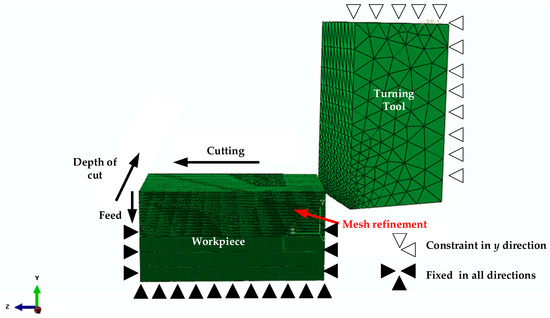
Figure 1.
Finite element model of SiCp/Al composites.
Since new cutting tools were adopted during all the turning experiments, the polycrystalline diamond (PCD) tools in simulation were defined as rigid bodies for the sake of reducing the computational time with no loss in calculation accuracy. The workpiece material was modeled as elastic-plastic and the material properties of 17vol.% SiCp/2009Al composites and PCD tool are listed in Table 1 [24,25].

Table 1.
Material properties of 17vol.% SiCp/2009Al composites and polycrystalline diamond (PCD) tool [24,25].
The improved Johnson–Cook constitute model considering the coupling effects of plastic strain, strain rate, and temperature was used for 17vol.% SiCp/2009Al composites, of which the material constants were identified using dynamic Split Hopkinson Pressure Bar experiments under different strain rates and temperatures [26]:
where , , and T are plastic strain, strain rate, and temperature; A is yield strength, B1 and B2 are strain hardening coefficients, W is a weighting coefficient, n1, n2, and n3 are thermal softening coefficients; and m and D are material constants. The constitutive material constants of 17vol.% SiCp/2009Al composites were determined according to [26].
The shear damage criterion was adopted to describe the damage caused by shear localization, and has the following expressions [27]:
and
where is the effective plastic strain at damage initiation, is a material parameter, and is the effective shear stress.
A scalar-valued damage factor for the shear criterion was used to determine the damage initiation:
where the onset of damage will initiate when the damage factor arrives at 1.
To avoid energy-dissipated effects caused by refining mesh, Hillerborg’s stress-displacement law was introduced by fracture energy :
where is the characteristic length of element, and are plastic displacement and strain at the onset of damage, and and are displacement and strain at failure.
In the present study, the physical chip separation criterion available for finite element codes was adopted in the turning simulation, which is based on the equivalent plastic strain . As the equivalent plastic strain of one element arrives at a critical value , the value of the damage state variable D in Equation (7) reaches one. When the critical value requirement is satisfied, the material failure will be triggered, followed by the corresponding element deletion and chip separation.
The friction model over tool–chip and tool–workpiece interfaces adopts the slipping/sticking contact conditions suggested by Zorev [28]. The contact formula along the interface tangential directions are given according to slipping () and sticking zones:
where is the critical shear stress.
Three-dimensional, eight-node thermal coupling hexahedron elements with reduced integration (C3D8RT) were employed to divide the workpiece mesh, and a three-dimensional tetrahedron element (C3D4T) was used to define the tool. The constraint conditions of the workpiece in any direction are shown in Figure 1, and the cutting tool was given a predetermined speed along the cutting direction and feed directions, respectively.
3. Materials and Experimental Procedures
The 17vol.% SiCp/2009Al composites were prefabricated using powder metallurgy, and the extrusion ratio was 15:1. This composite was T4 treated: solution treating at 500 °C for 120 min, followed by water quenching and natural aging for 4 d. The microstructure is illustrated in Figure 2. It can be observed that SiC particles were homogeneously distributed in the 2009Al matrix microstructure and the average size of SiC particles was approximately 7 μm. Turning experiments were conducted for model validation. Figure 3 illustrates the experimental setup, and the prepared cylindrical specimen was 150 mm in diameter and 200 mm in length. As shown in Figure 3, the inclination angle of the diamond cutting tool was adjusted according to the assigned oblique angle before each cutting test.
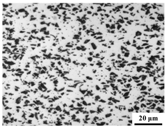
Figure 2.
Microstructure of 17vol.% SiCp/2009Al composites.
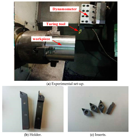
Figure 3.
Schematic illustration of the experimental set-up for turning 17vol.% SiCp/2009Al composites.
In order to obtain the edge quality under different cutting parameters, a number of grooves were machined to a surface structure of 3 mm in width and 6 mm in depth. All the machining experiments were conducted on a CNC lathe machine shown in Figure 2, and the details of the machining experimental conditions are summarized in Table 2. The turning experiments of 17vol.% SiCp/2009Al composites were conducted using SYNDITE PCD CTH025 from Element Six Co., which has an average grain size of 25 μm, high wear resistance, and has been successfully used in the machining of metal matrix composites. The rake angle and clearance angle of PCD tools are respectively γ0 = 0° and α0 = 10°, and the inclination angle is λs = 10°. In the machining experiments, only one cutting parameter (e.g., the depth of cut) was changed while the feed rate and spindle speed remained the same, in order to analyze the individual influence of a cutting parameter on the edge defects at the exit end. After all the turning experiments, the morphologies and the sizes of edge defects at the exit end were examined using a 3D Laser Scanning Digital Microscope VK-X200 (Keyence, Osaka, Japan).
Table 2.
Summary of experimental conditions.
4. Results and Discussion
4.1. Formation Mechanism of Edge Defects
The main objective of the finite element (FE) analysis of turning 17vol.% SiCp/2009Al composites was to study the formation mechanism of edge defects, so as to provide theory and process guidance for the machining of 17vol.% SiCp/2009Al composites in order to reduce the edge defects at the exit end as much as possible. In terms of the distribution law of cutting-induced stress and the change of the chip morphology characteristics, the formation process of the edge defects was divided into eight stages, and they can explain the process very well. The first stage is the initial contact between the turning tool and chips as the turning tool cuts into the workpiece (shown in Figure 4a); it demonstrates a continuous cutting process, accompanied with the formation of non-continuous chips through shear deformation according to von Mises stress distribution, and the shear deformation zone can be obviously seen, where Φ is the shear angle and T0 the undeformed chip thickness. As the turning tool moves, the elastic deformation zone (less than the yield strength of 17vol.% SiCp/2009Al composites) appears at the workpiece edge due to the elastic bending, and meanwhile the plastic deformation zone around the shear zone was found to be propagated towards the edge at the exit end, as shown in Figure 4b,c. The figure shows that the plastic deformation zone extended near the workpiece edge and the plastic deformation zone near the shear zone continued to move forward and it moved towards connecting with the plastic deformation zone around the edge at the exit end. Figure 4d shows the critical transition stage: in the undeformed chip layer there was a stress transition zone where plastic deformation just arrived at the exit end, and at this time the distance between the tool nose point A and the workpiece exit end is thought to be a critical distance ω. The stress transition zone transferred the maximum equivalent stress to the edge at the exit end under the cutting path and impeded the formation of non-continuous chips, especially for hard brittle materials. Figure 4e shows the flexure deformation stage, and cutting shear action induced flexure deformation at the pivot point O. As the cutting proceeded, the location of pivot point gradually moved toward the cutting path. The stress concentration zone under the cutting path is also defined as the negative shear deformation zone, and the angle ψ between the cutting path and the connecting line from the point O to tool nose is called the negative shear angle. Figure 4f shows the stage of end crack initiation: as the cutting-induced stress level exceeded the tensile yield strength of brittle SiCp/2009Al composites, the cracks initiated near the tool nose, where the internal high-density dislocation occurred, and promoted the propagation of cracks into the negative shear deformation zone and grew towards the pivot point O. Figure 4g shows the stage of crack propagation along the negative shear angle: the crack propagation toward the pivot point O occurred. Additionally, a great many micro cracks under the mixed tensile and shear modes initiated inside the negative shear deformation zone, and these micro cracks further grew and coalesced under mixed loadings of cutting. At the same time, the edge at the workpiece exit end underwent slight deformation under the action of cutting forces, which also further promoted cracks propagation. The fracture separation stage is shown in Figure 4h. In this stage, when the tool nose approached the exit end and continuous crack propagation, a portion of the edge material was separated from the workpiece below the cutting path as the tool moved forward, which eventually led to the formation of the edge defects. The main parameters for characterizing the edge defects are the defect height H and defect length L, which are specifically illustrated in Figure 4h. Therefore, the formation of the edge defect at the exit end was mainly due to the fact that a great many micro cracks occurred near the tool nose because of the dislocation pileup and wear support as the tool gradually approached the exit end, and when these micro cracks grew into the negative shear deformation zone, the micro voids evolved from micro cracks grew along a new surface, of which the formation requires the release of the minimum energy, and these micro cracks/voids started propagating as soon as they arrived at a critical state, followed by micro cracks/voids coalescence. So, the negative shear angle and stress levels caused by chip formation and weak support at the workpiece exit end are very important evidence for judging edge defect formation and optimizing the machining process.
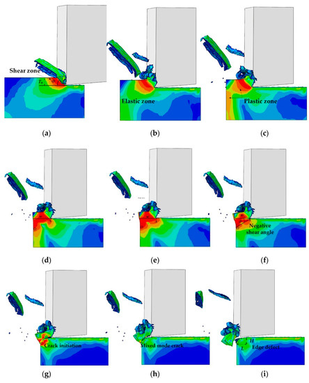
Figure 4.
Process of edge defect formation.
4.2. Edge Defects
For studying the morphologies and edge defect sizes at the workpiece exit end, only a small part containing the edge defects was cut from all the machined components using wire electrical discharge machining. When the feed rate and spindle speed were 0.237 mm/r and 500 r/min, respectively, the exit edge defect morphologies under five different depths of cut are displayed in Figure 5. Figure 5a–e shows the morphologies of the edge defects in the length direction, while Figure 5f–j show the morphology of the edge defects in the height direction. In Figure 5, we can clearly see that the brittle characteristics of 17vol.% SiCp/2009Al composites were very obvious, and brittle SiC particles in the Al matrix led to very rough fracture morphologies. As the depth of cut gradually increased, the values of length and height of the edge defects increased significantly.
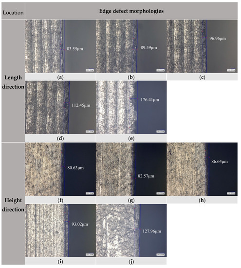
Figure 5.
Edge morphology on the exit surface, at the depth of cut of: (a,f) 1 mm, (b,g) 1.5 mm, (c,h) 2 mm, (d,i) 2.5 mm, (e,j) 3 mm.
4.3. Influence of Cutting Parameters on the Sizes of Edge Defects
Figure 6 shows the change law of the edge defect size at the workpiece exit end with the depth of cut, spindle speed, and feed. Figure 6a shows the influence of the depth of cut on the edge defect size at the exit end when the spindle speed and feed were respectively 500 r/min and 0.237 mm/r. It can be seen that the length and height of edge defects increased with the depth of cut. While the depth of cut was below 2.5 mm, the size of micro edge defects showed a slow increase. However, as the depth of cut continued to increase, the edge defect sizes increased very quickly. This is mainly because as the depth of cut increased above some value, the resultant higher cutting forces brought about severe and unstable cutting movement, which further promoted the formation of large edge defects at the exit end. Additionally, when the depth of cut and spindle speed were kept constant, the influence of the feed on the edge defect size is illustrated in Figure 6b. From the figure, it can be noted that as the feed rate increased, the size of micro edge defects at the exit end significantly increased, and there was a linear increasing relation between edge defect size and feed rate. Figure 6c presents the dependence of edge defect size on spindle speed, and it can be seen that the spindle speed had a lesser influence on the size of the exit edge defect. This is because the brittle SiC particles in the 2009Al matrix led to no significant softening effects in the 17vol.% SiCp/2009Al composites. Similar observations were also reported in [10,11] for the machining of SiCp/6061Al composites under different cutting parameters. Based on the above conclusions, to achieve high-quality turning operation with less edge defects and high dimensional accuracy, a smaller depth of cut and feed rate should be adopted in the turning of 17vol.% SiCp/2009Al composites, but in contrast, a high a spindle speed as possible should be employed.
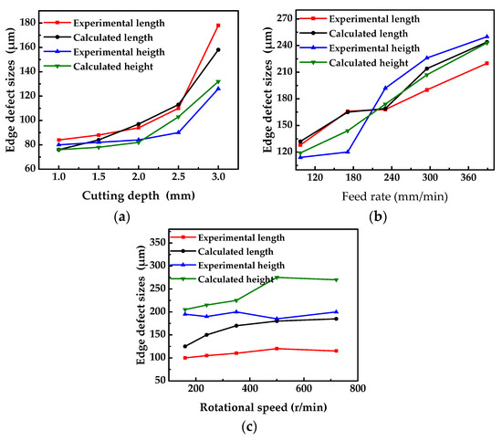
Figure 6.
Influence of cutting parameters (a) depth of cut, (b) feed rate, and (c) spindle speed on edge defect sizes.
From Figure 6a–c, it is very remarkable that for edge defect size, the curves of simulation results were smoother than those of experimental observation, and the simulation data were slightly less than the experimental ones. This can be explained by the simplification of finite element modelling for oblique cutting. In the present study, 17vol.% SiCp/2009Al composites were considered to be homogeneous and isotropic, and to have no defects. In fact, besides the tool wear and machine vibration, large numbers of micro defects in real 17vol.% SiCp/2009Al composites could give rise to larger edge defects in the turning experiment than that in the simulation calculation.
5. Conclusions
A three-dimensional large-deformation thermo-elastic-plastic FE model and experimental study for the oblique cutting of the turning of 17vol.% SiCp/2009Al composites in PCD tooling were performed in order to investigate the microscale mechanism of edge defect formation at the workpiece exit end, as well as the influence of the machining process on the size of edge defects. Good agreement was found between the experimental and calculated results. The numerical results on the dependence of edge defects on the machining parameters were also compared to those of the turning experimental data, and a good agreement was attained. The two main conclusions are as follows:
(1) As the tool gradually approaches the exit end, a great many micro cracks occur near the tool nose because of the dislocation pileup and wear support, and when these micro cracks grow into the negative shear deformation zone, the micro voids evolved from micro cracks grow along a new fracture, satisfying the minimum fracture energy release, and these micro cracks/voids start propagating when they arrive at a critical state, followed by the coalescence of micro cracks/voids. The crack initiation and propagation along the negative shear deformation plane results in edge defects. The negative shear angle and stress levels caused by chip formation and weak support at the workpiece exit end are very important evidence for judging edge defect formation and optimizing the machining process.
(2) The brittle characteristics of 17vol.% SiCp/2009Al composites were very obvious, and brittle SiC particles in the Al matrix led to very rough fracture morphologies. The length and height of edge defects increased with the depth of cut. While the depth of cut was below 2.5 mm, the size of micro edge defects showed a slow increase. As the feed rate increased, the size of micro edge defects at the exit end significantly increased, and there was a linear increasing relation between edge defect sizes and feed rate, while the spindle speed had a lesser influence on the size of the exit edge defects. Therefore, to achieve high-quality turning operation with less edge defects and high dimensional accuracy during the turning of 17vol.% SiCp/2009Al composites, as high a spindle speed as possible under a depth of cut below 2.5 mm should be employed, while smaller depth of cut and feed rate should be used.
Author Contributions
Methodology and experimental design, L.Z.; experiment and writing—original draft preparation, J.X. (Junfeng Xiang); writing—review and editing, J.Y.; experiment and data curation, P.G and J.X. (Jiaqing Xie).
Funding
This research was funded by the Natural Science Foundation of Shandong Province, grant NO. ZR2019MEE074, National Natural Science Foundation of China, grant NO. 51175353, Fundamental Research Funds for the Central Universities, grant NO. FRF-TP-18-007A1, Doctoral Research Fund of Shandong Jianzhu University grant No. XNBS1809.
Conflicts of Interest
The authors declare no conflict of interest.
References
- Liu, Z.Y.; Wang, Q.Z.; Xiao, B.L.; Ma, Z.Y. Clustering model on the tensile strength of PM processed SiCp/Al composites. Compos. Part A Appl. Sci. Manuf. 2010, 41, 1686–1692. [Google Scholar] [CrossRef]
- Xiang, J.F.; Xie, L.J.; Gao, F.N.; Zhang, Y.; Yi, J.; Wang, T.; Pang, S.Q.; Wang, X.B. On multi-objective based plastic constitutive modelling methodology and numerical validation in small-hole drilling of Al6063/SiCp composites. Materials 2018, 11, 97. [Google Scholar] [CrossRef] [PubMed]
- Balasubramanian, I.; Maheswaran, R. Effect of inclusion of SiC particulates on the mechanical resistance behaviour of stir-cast AA6063/SiC composites. Mater. Des. 2015, 65, 511–520. [Google Scholar] [CrossRef]
- Cui, Y.; Jin, T.Z.; Cao, L.G.; Liu, F.B. Aging behavior of high volume fraction SiCp/Al composites fabricated by pressureless infiltration. J. Alloys Compd. 2016, 681, 233–239. [Google Scholar] [CrossRef]
- Hu, F.Q.; Cao, F.Y.; Song, B.Y.; Hou, P.J.; Zhang, Y.; Chen, K.; Wei, J.Q. Surface properties of SiCp/Al composites by powder-mixed EDM. Procedia CIRP 2013, 6, 101–106. [Google Scholar] [CrossRef]
- Sahin, Y.; Sur, G. The effect of Al2O3, TiN and Ti (C,N) based CVD coatings on tool wear in machining metal matrix composites. Surf. Coat. Technol. 2004, 179, 349–355. [Google Scholar] [CrossRef]
- Xiang, J.F.; Xie, L.J.; Hu, X.; Peng, S.; Wang, T. Investigation of cutting forces, surface integrity, and tool wear when high-speed milling of high-volume fraction SiCp/Al6063 composites in PCD tooling. Int. J. Adv. Manuf. Technol. 2018, 98, 1237–1251. [Google Scholar] [CrossRef]
- Xiang, J.F.; Pang, S.Q.; Xie, L.J.; Gao, F.N.; Hu, X.; Yi, J.; Hu, F. Mechanism-Based FE Simulation of Tool Wear in Diamond Drilling of SiCp/Al Composites. Materials 2018, 11, 252. [Google Scholar] [CrossRef] [PubMed]
- Di Ilio, A.; Paoletti, A. A comparison between conventional abrasives and superabrasives in grinding of SiC-aluminium composites. Int. J. Mach. Tools Manuf. 2000, 40, 173–184. [Google Scholar] [CrossRef]
- Xiang, J.F.; Xie, L.J.; Gao, F.N.; Yi, J.; Pang, S.Q.; Wang, X.B. Diamond tools wear in drilling of SiCp/Al matrix composites containing Copper. Ceram. Int. 2018, 44, 5341–5351. [Google Scholar] [CrossRef]
- Ge, Y.F.; Xu, J.H.; Yang, H.; Luo, S.B.; Fu, Y.C. Workpiece surface quality when ultra-precision turning of SiCp/Al composites. J. Mater. Process. Technol. 2008, 203, 166–175. [Google Scholar] [CrossRef]
- Pramanik, A.; Zhang, L.C.; Arsecularatne, J.A. Machining of metal matrix composites: Effect of ceramic particles on residual stress, surface roughness and chip formation. Int. J. Mach. Tools Manuf. 2008, 48, 1613–1625. [Google Scholar] [CrossRef]
- Dabade, U.A.; Joshi, S.S. Analysis of chip formation mechanism in machining of Al/SiCp metal matrix composites. J. Mater. Process. Technol. 2009, 209, 4704–4710. [Google Scholar] [CrossRef]
- Xiang, J.F.; Xie, L.J.; Hu, X.; Huo, S.Y.; Pang, S.Q.; Wang, X.B. Simulation and Experimental Research on Ultra-precision Turning of SiCp/Al Composites. Rare Met. Mater. Eng. 2019, 48, 1687–1696. [Google Scholar]
- Chern, G.L. Study on mechanisms of burr formation and edge breakout near the exit of orthogonal cutting. J. Mater. Process. Technol. 2006, 176, 152–157. [Google Scholar] [CrossRef]
- Chern, G.L. Study on a new turning method to simulate orthogonal cutting and to verify an edge breakout mode. Int. J. Adv. Manuf. Technol. 2005, 26, 965–969. [Google Scholar] [CrossRef]
- Ko, S.L.; Dornfeld, D.A. Burr formation and fracture in oblique cutting. J. Mater. Process. Technol. 1996, 62, 24–36. [Google Scholar] [CrossRef]
- Hashimura, M.; Ueda, K.; Dornfeld, D. Analysis of three-dimensional burr formation in oblique cutting. CIRP Ann. Manuf. Technol. 1995, 44, 27–30. [Google Scholar] [CrossRef]
- Gaitonde, V.N.; Karnik, S.R.; Rubio, J.C.; Correia, A.E.; Abrao, A.M.; Davim, J.P. Analysis of parametric influence on delamination in high-speed drilling of carbon fiber reinforced plastic composites. J. Mater. Process. Technol. 2008, 203, 431–438. [Google Scholar] [CrossRef]
- Tsao, C.C. Effect of induced bending moment (IBM) on critical thrust force for delamination in step drilling of composites. Int. J. Mach. Tools Manuf. 2012, 59, 1–5. [Google Scholar] [CrossRef]
- Tsao, C.C.; Hocheng, H. Effect of tool wear on delamination in drilling composite materials. Int. J. Mech. Sci. 2007, 49, 983–988. [Google Scholar] [CrossRef]
- Lazar, M.B.; Xirouchakis, P. Experimental analysis of drilling fiber reinforced composites. Int. J. Mach. Tools Manuf. 2011, 51, 937–946. [Google Scholar] [CrossRef]
- Arul, S.; Vijayaraghavan, L.; Malhotra, S.K.; Krishnamurthy, R. The effect of vibratory drilling on hole quality in polymeric composites. Int. J. Mach. Tools Manuf. 2006, 46, 252–259. [Google Scholar] [CrossRef]
- Tan, Y.Q.; Yang, D.M.; Sheng, Y. Discrete element method (DEM) modeling of fracture and damage in the machining process of polycrystalline SiC. J. Eur. Ceram. Soc. 2009, 29, 1029–1037. [Google Scholar] [CrossRef]
- Zhou, L.; Huang, Z.Y.; Wang, C.Z.; Zhang, X.X.; Xiao, B.L.; Ma, Z.Y. Constitutive flow behaviour and finite element simulation of hot rolling of SiCp/2009Al composite. Mech. Mater. 2016, 93, 32–42. [Google Scholar] [CrossRef]
- Xiang, J.F.; Xie, L.J.; Gao, F.N.; Yi, J.; Pang, S.Q. Methodology for dependence-based integrated constitutive modelling: An illustrative application to SiCp/Al composites. Ceram. Int. 2018, 44, 11765–11777. [Google Scholar] [CrossRef]
- Hooputra, H.; Gese, H.; Dell, H.; Werner, H. A comprehensive failure model for crashworthiness simulation of aluminum extrusions. Int. J. Crashworthiness 2004, 9, 449–464. [Google Scholar] [CrossRef]
- Zorev, N.N. Inter-relationship between shear processes occurring along tool face and shear plane in metal cutting. Int. Res. Prod. Eng. 1963, 49, 143–152. [Google Scholar]


© 2019 by the authors. Licensee MDPI, Basel, Switzerland. This article is an open access article distributed under the terms and conditions of the Creative Commons Attribution (CC BY) license (http://creativecommons.org/licenses/by/4.0/).