Article

Deflection Reduction Shaping Commands with Asymmetric First-Order Actuators

Department of Mechanical Engineering, Chosun University, Gwangju 61452, Korea
*
Author to whom correspondence should be addressed.
Appl. Sci. 2019, 9(19), 3982; https://doi.org/10.3390/app9193982
Submission received: 22 August 2019 / Revised: 17 September 2019 / Accepted: 18 September 2019 / Published: 23 September 2019
(This article belongs to the Section Mechanical Engineering)

Abstract

:
In this paper, two approaches for generating deflection reduction shaping commands are proposed to reduce the transient and residual deflections of flexible systems subject to asymmetric first-order actuators. The commands are limited-state in that they consist of two positive actuations of different magnitudes and one negative actuation, similar to on-off-on commands. Standard on–off commands that are commonly used in robots, cranes, and spacecrafts can degrade the control performance of conventional input-shaped commands and cause detrimental damage resulting from large transient deflections of flexible structures due to asymmetric first-order actuators. Therefore, to cope with the performance degradation resulting from the effects of first-order actuators, an approximated closed-form solution and a numerically optimized approach for deflection reduction shaping commands are presented with an exponential function, final impulse magnitude modification of an input shaper is determined by a transient deflection constraint and a phasor vector approach. The performance assessment showed that the approximated analytical approach has an advantage in real-time control applications. The characteristics of the proposed deflection reduction shaping commands are analyzed with respect to system parameters, deflection reduction ratios, and actuator time constants. The proposed command shaping techniques are numerically evaluated using a pendulum system and are experimentally validated on a mini-bridge crane.

1. Introduction

Input shaped commands with standard on-off actuators have been effectively used without large transient and residual deflections of linear flexible systems such as those applied in large cranes, robot manipulators, microstages and space structures [1,2,3,4]. However, the conventional input shaping approach [5,6,7] should be modified to account for asymmetric first-order dynamics resulting from the nonlinear effects of a separate actuation mechanism, non-co-located actuators, electric motors, or unilaterally dispersed dynamics. Even if an input-shaped command is properly designed for elastic modes, a shaped command deviated by the asymmetric first- order actuator could deteriorate control performance and may even lead to system instability in precision process control. As a result, large transient and residual deflections may occur in flexible systems. The objective was to develop two command-shaping approaches with the limited-state operation of asymmetric first-order actuators while reducing the transient and residual deflections of elastic modes.
Many techniques have been proposed to generate input shaped commands that are time optimal [8,9,10,11], limit transient deflection [12], and limit fuel consumption [13,14] using reliable optimization algorithms. Some practical developments based on input shaping have been made by considering robustness [15], limitation of transient deflection [16], and fuel efficiency [17]. As one of the open-loop control approaches, the input shaping process is implemented by convolving a reference command with a sequence of impulses of an input shaper. While many input shaping techniques have been derived primarily from linear system theory [5,6], there is much interest in the application of input shaping to non-ideal systems with control performance constraints.
A deflection-reduction shaping approach for on-off commands was initially formulated via parameter optimization with a deflection constraint [18]. Several alternative approaches to this formulation were presented by applying a deflection limit to either all or a sampling of local extrema points throughout the entire transient deflection. Thereafter, a closed-form solution for limited-state commands was proposed by adjusting the final impulse magnitude of the unit magnitude zero vibration (UMZV) shaper with the summation of deflection responses to multiple step inputs [19]. As an extension of their previous approach, a robust approach was proposed with parameter optimization to determine additional impulse times [20]. An analytical deflection-limiting shaping approach was also presented under the velocity constraint of electric motors [21]. To constrain the transient deflection of the flexible mode, a time-optimal control profile was parameterized in terms of a permissible deflection value. These deflection reduction shaper approaches have been developed only under ideal on–off actuator operations to limit the transient and residual deflections within a specified bound.
Nonlinear systems can be problematic in the application of input shapers because they are based on linear system theory. As a nonlinearity source, actuator nonlinearities can be described by discontinuous nonlinearities within a system, such as backlash, saturation, rate limiting, and dead zone. When an actuator nonlinearity deviates an input-shaped command, the oscillation-reducing performance of the shaped command can be significantly degraded. To reduce the detrimental effects of actuator nonlinearities, input shaper redesign techniques have been established from the perspective of rate limits [22,23], backlash [24], and Coulomb friction [25,26]. In addition, on-off shaping techniques were developed for non-ideal input commands distorted by asymmetrical delayed first-order actuators [27] and second-order actuators [28]. In these approaches, even if actuator nonlinearities were directly considered for an input shaper redesign, simultaneous consideration of the transient and residual deflection reductions of the flexible modes were not undertaken.
For the transient and residual deflection reduction with limited-state commands, a unit magnitude zero vibration shaper with asymmetric first-order actuators (UMZVDRF) is analytically developed with the phasor vector diagram for an input shaper redesign and an approximated deflection expression to limit transient deflection with respect to multiple step inputs. In the next section, an optimized unit magnitude shaper with asymmetric first-order actuators, so called UMZVDRFO, is formulated with the parameter optimization formulation and the modified expression of the final impulse amplitude of the input shapers for either an alternative shaping command design or a justification of the proposed approximated approach. The proposed input shaping controllers are numerically analyzed with respect to system parameters, deflection reduction ratios, and actuator time constants using a benchmark model. Lastly, the deflection reduction shaping commands are experimentally validated using a mini-bridge crane.

2. Materials and Methods

In this section, two approaches for generating deflection reduction shaping commands are developed to reduce the transient and residual oscillations for control systems with a single flexible mode operated with asymmetric first-order actuators. First, an analytical input shaping technique is presented with a simplified response expression to approximate the final limited impulse magnitude of the input shaper and an exponential expression to mimic first-order actuator dynamics. Second, an optimized deflection reduction shaping technique is proposed for an alternative technique with a parameter optimization and for justification of the approximated analytical technique.

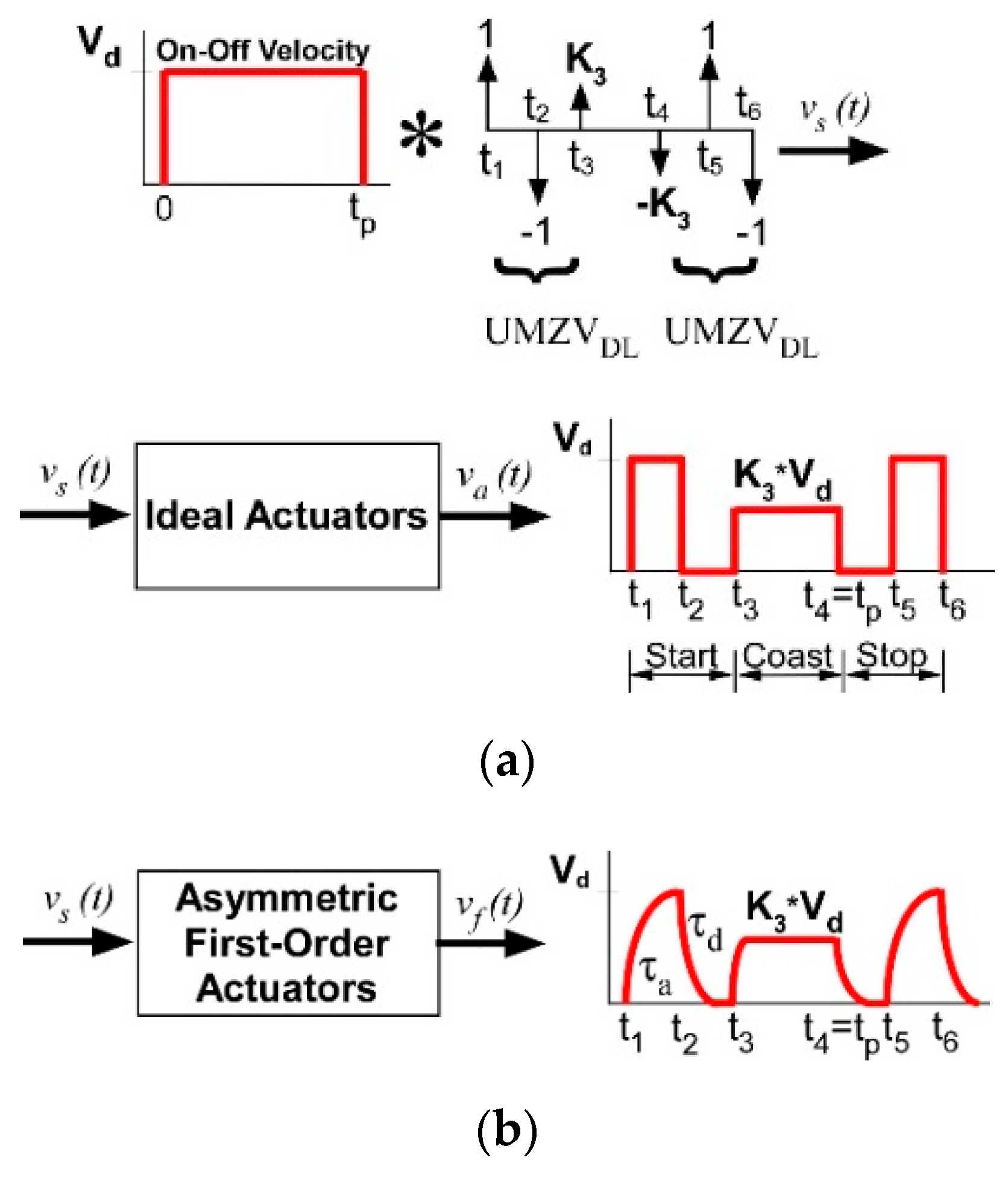
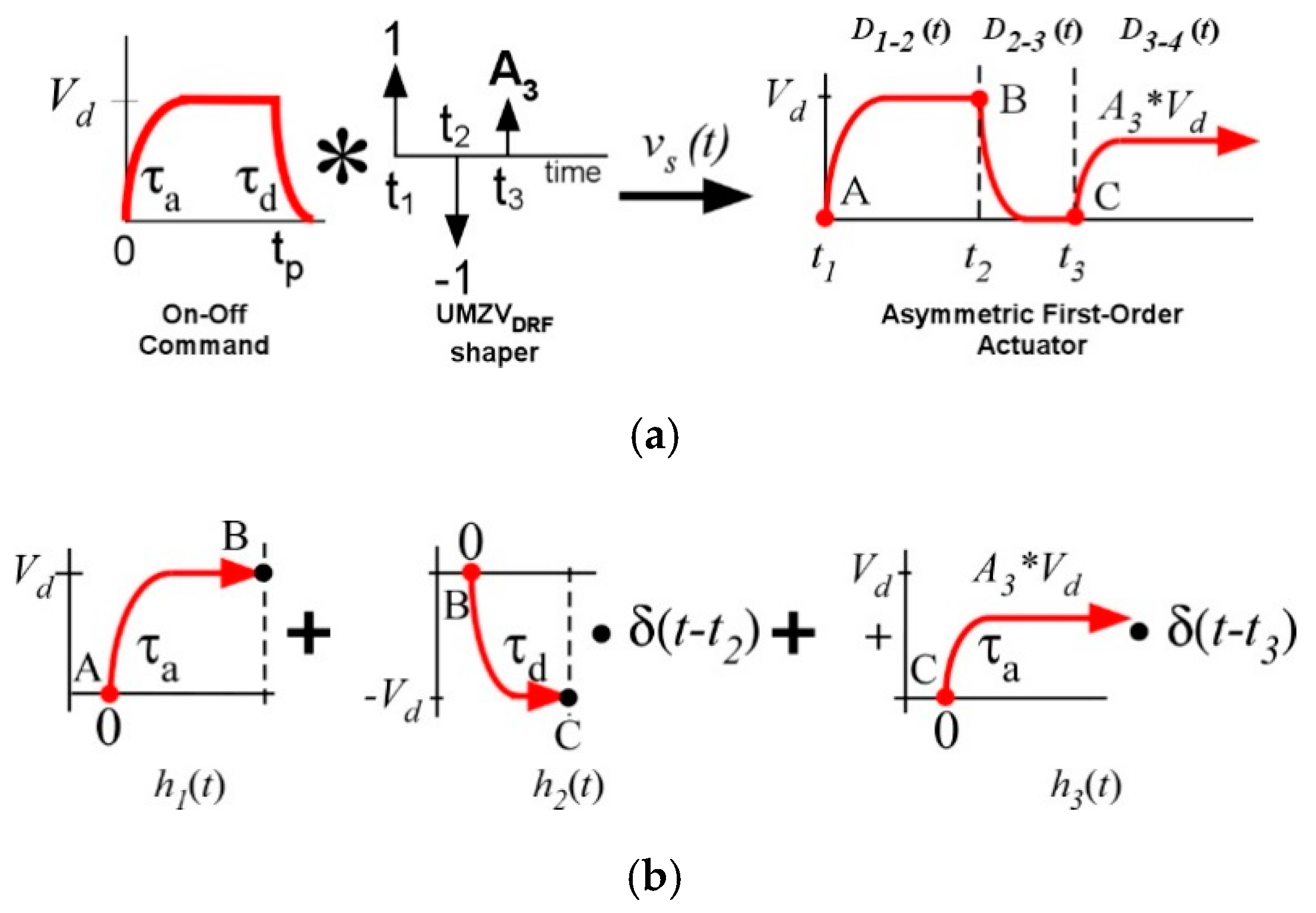
2.1. Analytical Deflection Reduction Shaping Command

A closed-form deflection reduction input shaper, the so-called UMZVDRF shaper, is developed to generate on–off command profiles under asymmetric first-order actuators based on a deflection-limiting input shaper, the UMZVDL shaper, as follows [18]:
{ A i t i } = [ 1 1 K 3 0 { c o s 1 ( 1 K 3 2 / 2 ) } / ω n { c o s 1 ( K 3 / 2 ) } / ω n ]
where ω n , A i , and t i are the natural frequency of a mass–spring–mass system and the magnitude and time of the i t h impulse, respectively; the final limited impulse magnitude is defined as K 3 = 2 · D l i m ; and the deflection limit, 0 < D l i m 0.5 , is defined as the ratio between the allowable and maximum deflections. The UMZVDL shaper is convolved with a pulse input such that the shaped commands are shown as on–off command profiles and lead to zero transient and residual oscillations for ideal flexible systems. However, if the shaped command is applied to a flexible system with asymmetric first-order actuators, the control performance is degraded because of the distorted command, as shown in Figure 1. Therefore, a deflection reduction shaped command is newly required to account for asymmetric first-order actuators.
First, for the deflection limit of a linear pendulum system, an expression for the deflection as a function of the input shaper must be obtained to limit the transient deflection of the flexible mode. The desired function can be derived using superposition of deflections from individual first-order response functions to a step input. The derivation begins with the equation for modelling the payload for the pendulum system in Figure 2 as follows:
L   θ ¨ ( t ) + g   s i n   θ ( t ) = u ( t )   c o s   θ ( t )
where u ( t ) = v ˙ f ( t ) is the time derivative of velocity input command, L is the length of a cable, and g is the gravity constant. With the assumption of a small angle θ ( t ) and zero initial conditions for the development of input shaped commands, Equation (2) can be expressed with the Laplace transform as follows:
Θ ( s ) = s   V f ( s ) L 1 s 2 + ω n 2
where ω n = L / g is the natural frequency of the pendulum system and V f ( s ) is the Laplace transform of v f ( t ) .
The start-up portion of the velocity profile in Figure 1b consists of a first-order response to a step command. The velocity command can be expressed as V f ( s ) = A · V d   { 1 / s 1 / ( s + 1 / τ ) } where A , τ, and V d are the magnitude of the shaped input command, time constant, and desired velocity magnitude, respectively. Substituting V f ( s ) into Equation (3) and taking the inverse Laplace transformation with zero initial conditions yields the deflection as follows:
θ ( t ) = A · V d L   ω n ( 1 + ω n 2 τ 2 ) { s i n ( ω n t ) ω n · τ · c o s ( ω n t ) + ω n · τ · e t / τ }
The deflection is approximately presented with the property of a sinusoidal function and the simplified expression assuming e t / τ 0 rapidly in time is as follows:
θ ( t ) = A · V d 1 + + ω n 2   τ 2 L   ω n ( 1 +   ω n 2   τ 2 ) [ sin { ω n t tan 1 ( ω n · τ ) } ]
With this approximated expression of a single first-order response to a step input, the final limited magnitude can be easily obtained to limit the transient deflections. Later, the negligence of the exponential term will be justified by comparing the control performance to an optimized solution. The complete pure deflection resulting from a first-order actuator as shown in Figure 3a can be expressed with the superposition principle as follows:
D ( t ) = i = 1 3 D i i + 1 ( t ) = i = 1 3 A i · D m i [ sin { ω n t tan 1 ( ω n · τ i ) } ] ( t t i )
where ( t t i ) is a Heaviside step function with the impulse time location t i of input shaper and the maximum deflection magnitude of each division D m i is defined as follows:
D m i = V d 1 + ω n 2   τ i 2 L   ω n ( 1 + ω n 2   τ i 2 )
and A i = [ 1 ,   1 ,   A 3 ] are defined and τ i = [ τ a ,   τ d , τ a ] are the time constants depending on first-order actuator dynamics as shown in Figure 3b. Equation (6) amounts to a piecewise continuous function consisting of 3 finite length segments with a limited range of applicability. Note that the magnitude of the deflection produced by a series of first-order response functions can exceed the maximum magnitude of D ( t ) if the deflection components from individual first-order response functions constructively interfere.
From Equation (6), the final limited impulse magnitude A 3 to maintain the transient deflection can be determined below a specific limit by satisfying the following constraint:
i = 1 3 A i · D m i [ sin { ω n t tan 1 ( ω n · τ i ) } ] ( t t i ) D E F f l i m
where D E F f l i m is the first-order deflection limit. To meet the constraint Equation (8), the constraint can be adjusted by equating both sides and the final limited impulse magnitude A 3 to control the transient deflection constraint can be solved as follows:
A 3 = D f l i m + { 1 + ( ω n τ a ) 2 } 1 + ω n 2 τ d 2 { 1 + ( ω n τ d ) 2 } 1 + ω n 2 τ a 2 1
where a non-dimensional ratio D f l i m = D E F f l i m / D m 1 is defined with respect to the largest magnitude D m 1 influencing the deflection response. In the case of time constants τ a = τ d = 0 for ideal actuators, Equation (9) is expressed as A 3 = D f l i m , implying a selection range 0 < D f l i m 1 , and resulting in the relation D f l i m = 2 · D l i m between the UMZVDRF and UMZVDRF shapers.
Second, with a desired transient deflection limit Equation (9), the impulse times of the UMZVDRF shaper can be solved for zero residual oscillation by utilizing a phasor vector approach. With the modified input command instead of an on–off velocity command based on linear system theory, the command design procedure can be simplified with the transformation into an equivalent command process as shown in Figure 3a. The start portion of the velocity profile can be represented as a function of the step times t 1 , t 2 , and t 3 as shown in Figure 1b and denoted as the following equation:
v f ( t ) = i = 1 3 h i ( t )
where:
h 1 ( t ) = V d ( 1 e t / τ a ) ( t t 1 ) h 2 ( t ) = V d ( 1 e t / τ d ) ( t t 2 ) h 3 ( t ) = A 3 V d ( 1 e t / τ a ) ( t t 3 )
Each term consists of a first-order response to a step command convolved with a time-delayed impulse. Because the input shaping technique focuses on zero residual oscillation, the steady-state response of the pendulum system from Equations (2)–(10) can be derived from the superposition principle as follows:
θ s s ( t ) = i = 1 3 v i ( t )
where v i ( t ) is the deflection resulting from the ith term in Equation (10) and is expressed by the following:
v i ( t ) = 1 L   | H i |   sin { ω n t ω n t i π 2 + H i } .
where:
| H 1 | = V d ω n ( τ a ω n ) 2 + 1 ,   H 1 = t a n 1 ( 1 τ a ω n ) π | H 2 | = V d ω n ( τ d ω n ) 2 + 1 ,   H 2 = t a n 1 ( 1 τ d ω n ) | H 3 | = A 3 | H 1 | ,   H 3 = H 1
With the phasor vector notation of the sinusoidal expression of Equation (11), the residual oscillation magnitude can be rewritten considering a geometric approach, to find the second and third impulse times that will yield zero residual oscillation as follows:
Amp ( t 1 ,   t 2 , t 3 ) = | i = 1 3 H i |
where:
| H i | = | H i | L ,   H i = ω n t i π 2 + H i
With the normalization of the phasor vectors with respect to | H 1 | and the first impulse time t 1 = 0 , the phasor components are expressed as follows:
| H 1 | = 1 ,   H 1 = 0
| H 2 | = ( τ a ω n ) 2 + 1 ( τ d ω n ) 2 + 1 ,   H 2 = ω n t 2 + t a n 1 ( 1 τ a ω n ) t a n 1 ( 1 τ d ω n )
| H 3 | = A 3 ,   H 3 = ω n t 3
When the three phasor vectors sum to zero, they can be placed as a triangle in the vector space as shown in Figure 4 and the magnitude of the residual oscillation Amp ( t 1 ,   t 2 , t 3 ) is zero. By solving for α 2 and α 3 with the law of cosines and Equation (13), respectively, the impulse times of the UMZVDRF shaper for the start motion yield are as follows:
t 2 = 1 ω n [ β 1 + cos 1 { ( γ 1 2 A 3 2 + 1 ) / 2 γ 1 } ]
t 3 = 1 ω n cos 1 { ( γ 1 2 A 3 2 1 ) / 2 A 3 }
β 1 = t a n 1 ( 1 τ a ω n ) t a n 1 ( 1 τ d ω n ) γ 1 = ( τ a ω n ) 2 + 1 ( τ d ω n ) 2 + 1
The switching times of the UMZVDRF shaper for stop motion can be obtained from a similar procedure to that of the start motion. However, the signs of the impulse magnitude are asymmetrically changed. The switching times for the stop motion are expressed as follows:
t 5 = t 4 + 1 ω n [ β 2 + cos 1 { ( γ 1 2 A 3 2 + 1 ) / 2 A 3 γ 2 } ]
t 6 = t 4 + 1 ω n cos 1 { ( γ 2 2 A 3 2 1 ) / 2 A 3 }
where t 4 = t p is the duration of the switch-on time and β 2 = β 1 and γ 2 = 1 / γ 1 are defined. From Equations (17)–(20), the entire UMZVDRF shaper for the start and stop commands of flexible systems is presented as follows:
[ A i t i ] = [ 1 1 A 3 A 3 1 1 t 1 t 2 t 3 t p t 5 t 6 ]
The aforementioned equation is utilized to produce the deflection reduction shaping commands under asymmetric first-order actuators with convolution of arbitrary on–off commands. To maintain the control performance of the proposed input shaper, the rise time of each input velocity should be ensured due to the time delay effect of first-order actuator dynamics.

2.2. Optimized Deflection Reduction Shaping Commands

The UMZVDRF shaper described in the previous section has the advantage of being derived in a closed-form solution by neglecting the exponential term. However, the approximated approach has an inevitable issue with respect to the control performance. For a problem outside of this approximation, a numerical optimization technique for deflection reduction shaping commands, the so-called UMZVDRFO, is developed with transient deflection reduction, zero residual oscillation, and time constant constraints.
To constraint the maximum transient deflection, the local extrema of the deflection function should be located and limited below the desired deflection magnitude at these instances. For the location of the extrema point, the deflection response before the third impulse is compactly expressed by utilizing Equation (4) as follows:
D o ( t ) = i = 1 2 A i   V d L   ω n ( 1 + ω n 2 τ i 2 ) [ 1 + ω n 2 τ i 2 sin { ω n   t tan 1 ( ω n   τ i ) } + ω n   τ i   e t τ i ] ( t t i )
where ( t t i ) is a Heaviside step function with the impulse time location t i of input shaper. To determine the design parameters t 2 , t 3 , and A 3 of the UMZVDRFO shaper, the maximum transient deflection of D o ( t ) should be satisfied as the following constraint:
max { D o ( t ) } D m a x · D f l i m
where D m a x is computed by the UMZVDRF shaped velocity command with A 3 = 1 and D f l i m = 1 . Equation (24) is compactly expressed through the time derivative of Equation (22) and is used to determine the time location at the maximum deflection as follows:
i = 1 2 A i   V d L ( 1 + ω n 2 τ i 2 ) [ 1 + ω n 2 τ i 2 cos { ω n   t   tan 1 ( ω n   τ i ) } e t τ i ] ( t t i ) = 0
Then, max { D o ( t ) } can be determined using Equation (22). In the process of numerical optimization, the time is computed by the fzero function in MATLAB©. The constraints on zero residual oscillation are expressed with the x-y vector components of Equations (14)–(16) as follows:
R x = 1 ( τ a ω n ) 2 + 1 ( τ d ω n ) 2 + 1 cos ( ω n t 2 + t a n 1 ( 1 τ a ω n ) t a n 1 ( 1 τ d ω n ) ) + A 3 cos ( ω n t 3 ) = 0
R y = ( τ a ω n ) 2 + 1 ( τ d ω n ) 2 + 1 sin ( ω n t 2 + t a n 1 ( 1 τ a ω n ) t a n 1 ( 1 τ d ω n ) ) + A 3 sin ( ω n t 3 ) = 0
Furthermore, an interval constraint between adjacent impulse times is included to maintain the acceptable control performance. Without collapsing the input commands, the following condition is enforced to ensure the rise time [29]:
t i + 1 t i > 2.2 τ i
where i = 1 3 for the index of the range division as shown in Figure 3. This condition is enforced to obtain acceptable control performance of the UMZVDRFO shaper without collapsing the command profile. Finally, the final impulse time t 3 is minimized to ensure the shortest duration shaper as follows:
J = m i n ( t 3 )
where t 1 = 0 is taken without losing the generality of the input shaper design. The computational procedure is summarized as follows:
step 1. 
Find the maximum deflection D m a x computed by Equation (22) at D f l i m = 1 and A 3 = 1 .
step 2. 
As an initial guess of the UMZVDRFO shaper, set up A 3 , t 2 and t 3 obtained by the UMZVDL shaper of Equation (1) with a desired ratio D l i m = D f l i m / 2 .
step 3. 
Minimize the cost function Equation (28) with constraint Equations (23), (25)–(27). At every constraint evaluation of Equation (23), max { D o ( t ) } is computed by utilizing Equations (22) and (24).
The impulse time sequence of the UMZVDRFO shaper can be obtained with the fmincon function in MATLAB©. For the impulse sequence of stop motion, the UMZVDRFO shaper, as in Equation (21), can be generated by asymmetrically utilizing t i , A i and τ i . The aforementioned constraint equations should be changed accordingly.

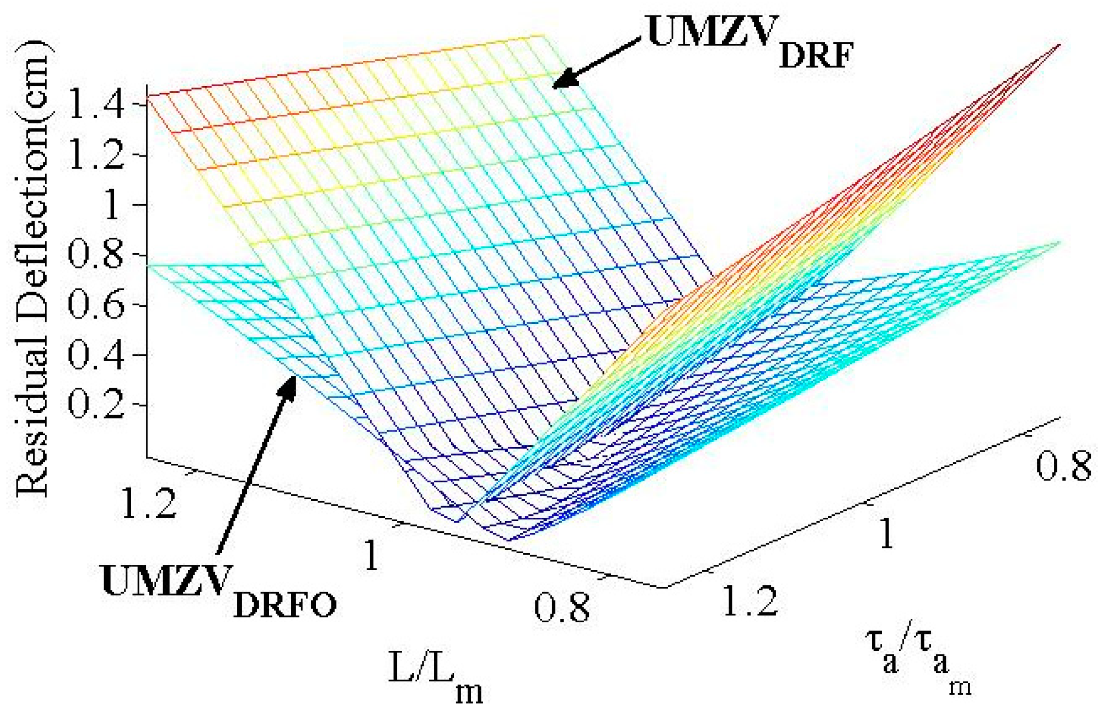
3. Numerical Results

The control performances of the proposed input shapers are evaluated in comparison to previously presented input shapers [18,19]. For numerical evaluation, the parameters are selected as τ a = 0.03   s , τ d = 0.01   s , L = 0.8   m , V d = 0.2   m / s , t p = 3   s , D l i m = 0.3 . and D f l i m = 0.6 . To initially start the parameter optimization, the UMZV DL shapers are used for the solution search of the UMZVDRF and UMZVDRFO shapers during the process of start and stop motions.
Because of the rise time, the effect of time-delayed commands is demonstrated by evaluating the solution range and maintaining the same values of the remaining analysis constants as shown in Figure 5. In the case of a long time constant, the shaped commands can be collapsed resulting in control performance degradation indicated as a range of no feasible solution. It is shown that the long length of the suspension cable can allow for a long time constant. Therefore, the proposed shaping technique should be utilized with a validation process of command profile completeness.
In addition, the residual maximum deflection is evaluated to illustrate the effect of the suspension cable length L as shown in Figure 6. The UMZVDRF shaper and UMZVDRFO shaper are superior to the UMZVDL shaper except for at a cable length L = 1   m . This result means that the first-order actuator dynamics should be considered for better control performance in the application of the input shaping technique.
To assess the internal command interference resulting from rising time delays of first-order actuators, the residual deflection is evaluated as a function of the switch-on time t p as shown in Figure 7. Even if negative commands are generated in the short and medium command regions, the UMZVDRF and UMZVDRFO shapers show better deflection reduction performance than the UMZVDL shaper. In the long command region, the UMZVDRF shaper shows the best control performance among the shapers with the selected parameters. Note that the switch-on time t p should be longer than the final impulse time of an input shaper to preserve the designed velocity command profile, although the performance degradation is small in the interference region.
For the evaluation of residual oscillation as shown in Figure 8, the UMZVDL shapers produce only a low oscillation magnitude at τ a = τ b . However, the UMZVDRF and UMZVDRFO shapers present much better residual deflection performance than that of the UMZVDL shaper within the entire evaluation range. In the difference plot, the UMZVDRFO shaper shows slightly better control performance than that of the UMZVDRF shaper owing to the approximation effect in the region of relatively large time constants.
Figure 9 and Figure 10 show the accuracy of assigned transient deflection limits in the case of D f l i m = [ 0.6 , 0.8 ] , which is the deflection percentage [60%, 80%] with respect to the maximum deflection determined by the UMZVDRF shaped velocity command as shown in Figure 3a with A 3 = 1 and D f l i m = 1 . The transient deflection limiting performance of the UMZVDRF shapers is degraded by the 10% discrepancy from that of the UMZVDRFO shapers because of the negligence of the exponential term. On the other hand, the UMZVDRFO shapers show accurate transient control performance as expected.
The numerical results obtained with respect to D f l i m = 1 mean there is no deflection limit while considering the time constants. The transient deflection limits are controlled by maintaining the consistent deflection magnitudes in the evaluation region. Based on the numerical analysis, the transient deflection magnitude can be slightly varied for τ a and τ d with regard to the deflection percentage.
Figure 11 and Figure 12 show the residual deflection reduction performance on the modeling uncertainty of the UMZVDRF and UMZVDRFO shapers with regard to reference parameter values τ a m , τ d m , and L m .
The sensitivity curves of both shapers in Figure 11 show very similar trends; they also imply that the UMZVDRFO shaper does not present much effect causing from of the neglected exponential term comparing to the UMZVDRF shaper. In Figure 12, the UMZVDRFO shaper shows better robustness to modeling uncertainty than that of the UMZVDRF shaper throughout the evaluation range.

4. Experimental Results

To experimentally evaluate the control performance of the proposed shapers, a mini-bridge crane as shown in Figure 13 was utilized. The schematic configuration in Figure 14 shows the essential Siemens® components of the mini-bridge crane. Its workspace is 1.3 m × 0.75 m in the horizontal directions and 1.4 m in the vertical direction. For the system operating program, the Simatic® modules of the CFC, SCL, and WinCC software are employed to upload and download the experimental data. A VS720-series intelligent vision sensor in conjunction with a vision program generated by the Spectation® software is used to measure the payload oscillation magnitude. Four limit sensors are used to detect the x and y- axis boundaries for overtravel prevention.

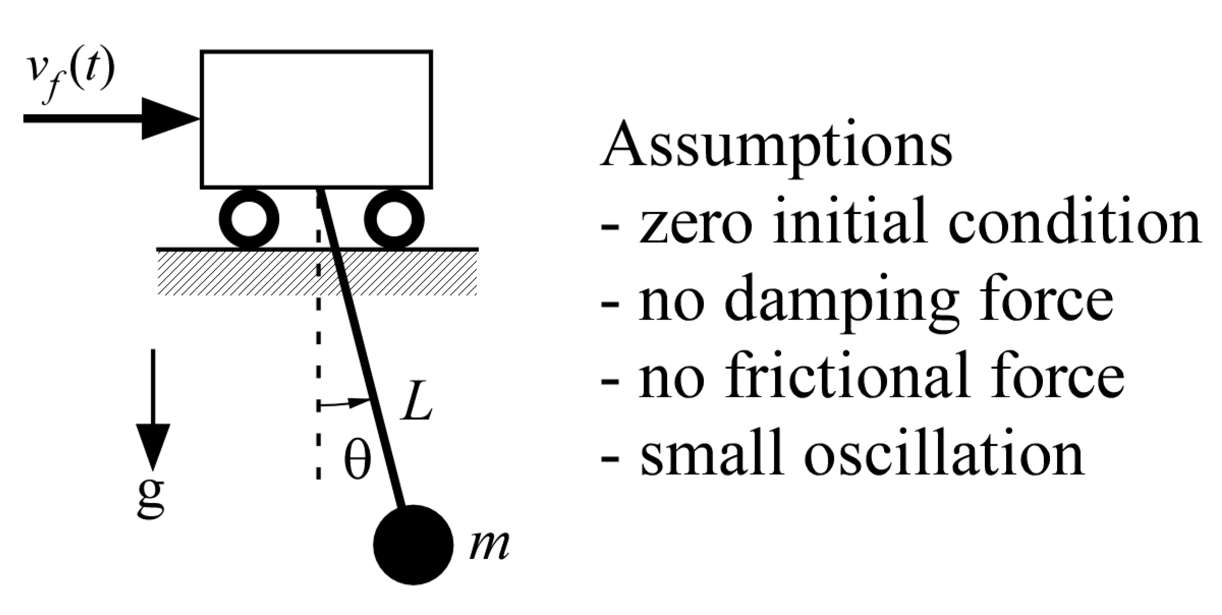
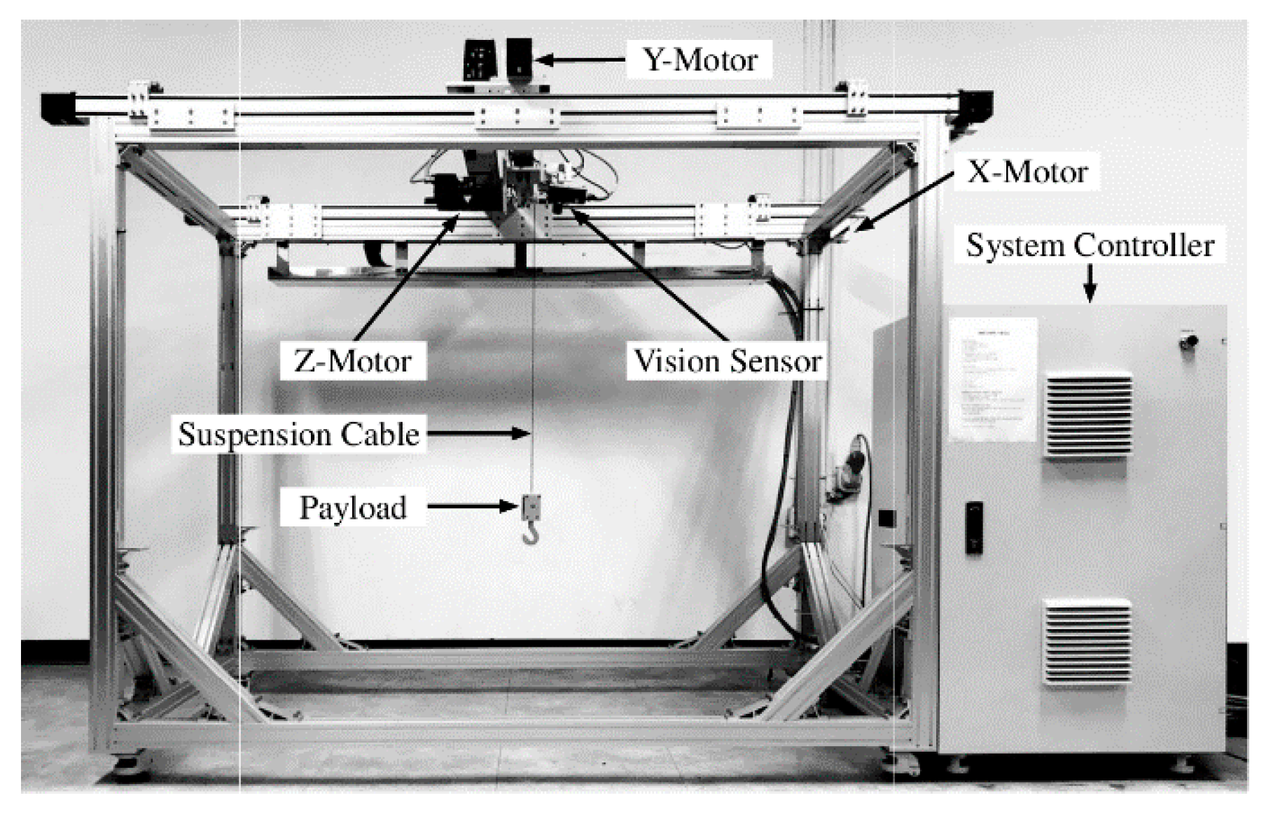
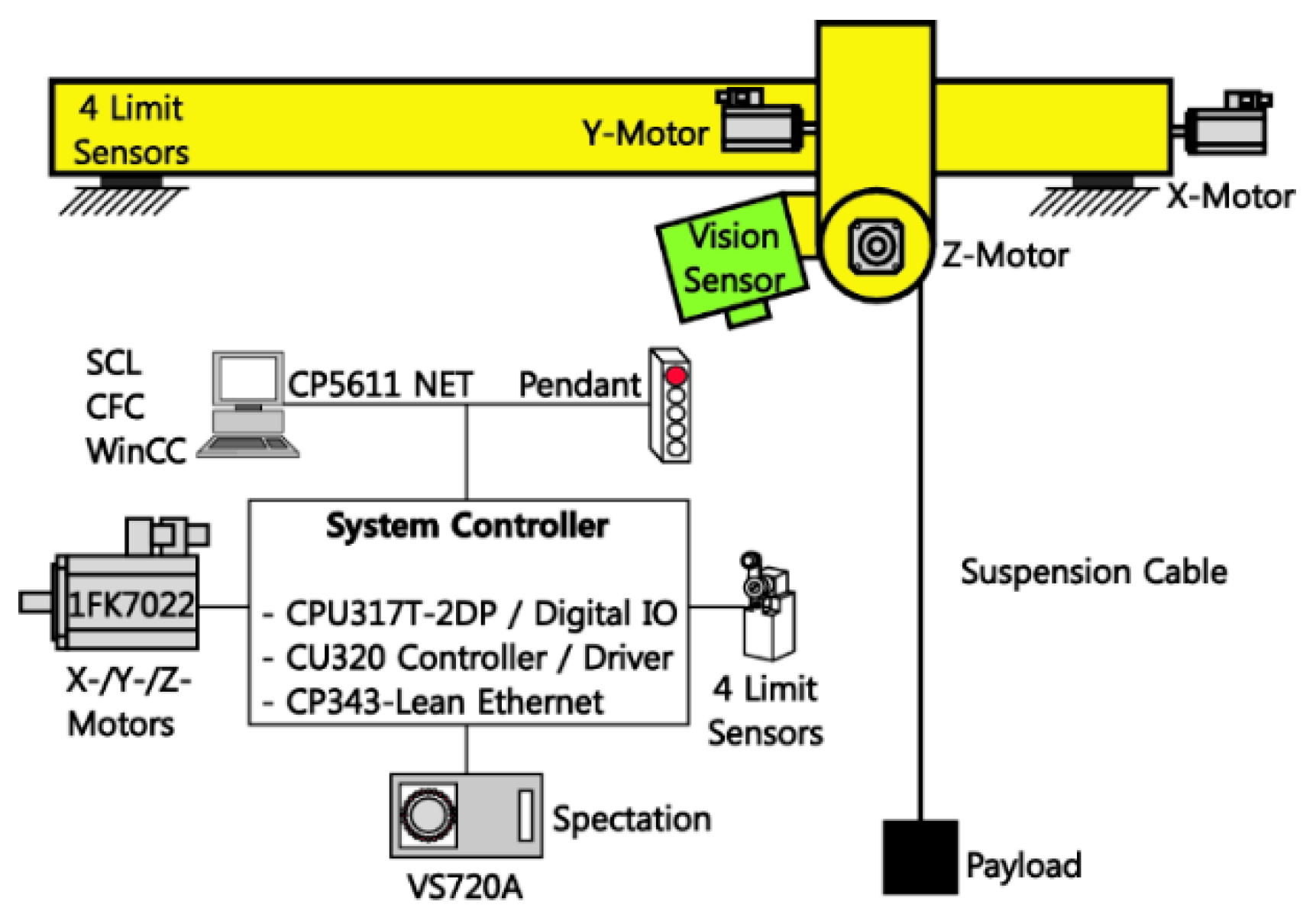
4.1. Experimental Set-Up

The experimental set-up was consistently employed for numerical analysis by selecting the default parameter selection as in Table 1. To accurately track the specifically designed velocity commands, the mini-bridge crane was configured with the appropriate proportional and integral (PI) gains of a motor control driver. To illustrate the experimental comparison, the typical input shapers for a start and stop motion are presented in Table 2.

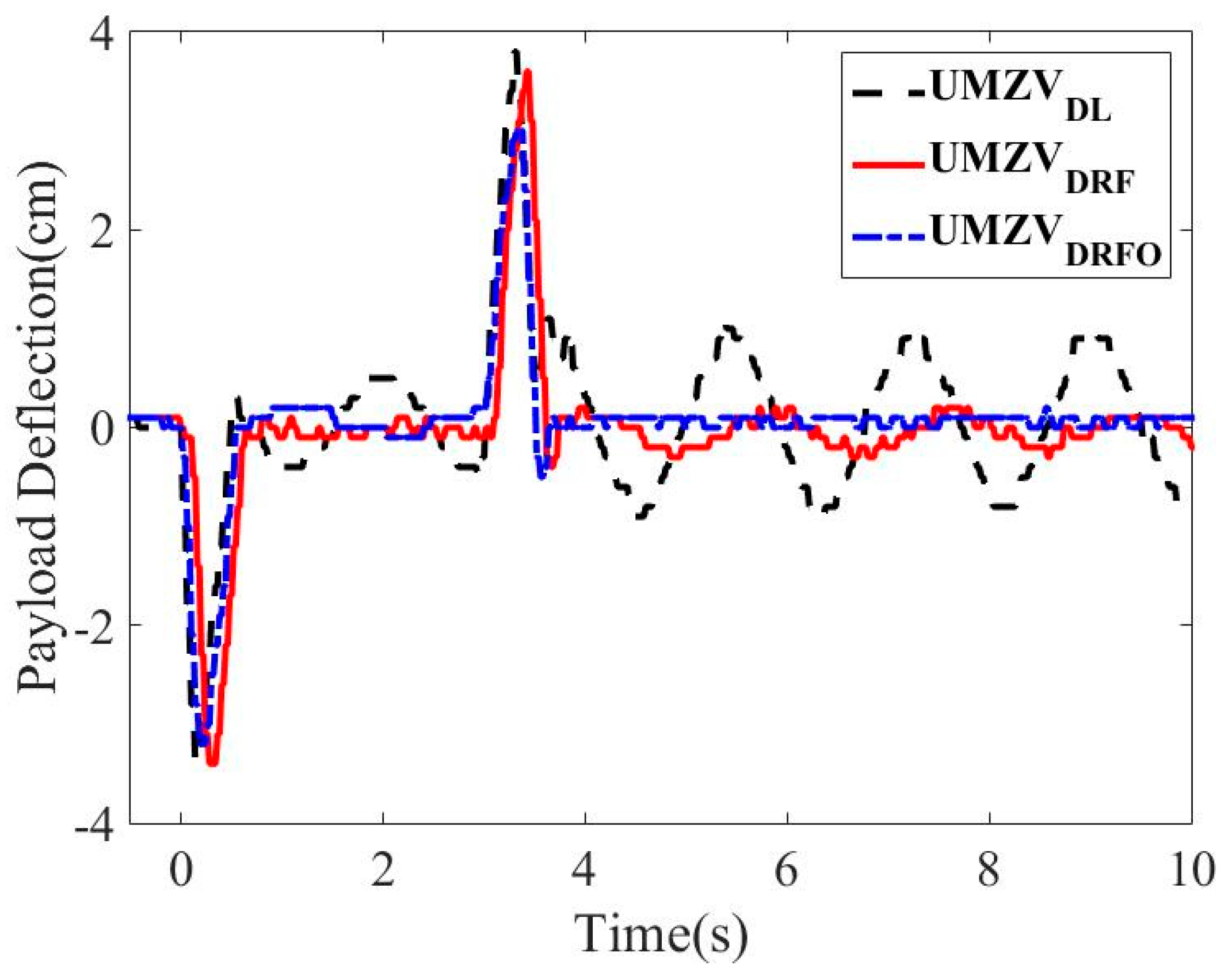
4.2. Experimental Assessment

The control performances of the UMZVDL, UMZVDRF, and UMZVDRFO shapers are experimentally verified from the aspects of transient and residual deflections and the robustness to modeling uncertainties. For a specific case, all three input shapers are presented with the magnitude difference of the UMZVDRFO shaper from the others as shown in Table 2 even if the UMZVDL shaper is utilized for the initial condition during numerical optimization. In addition, Figure 15 shows the first-order velocity commands applied to the mini-bridge crane and resulting in the time responses shown in Figure 16, where the UMZVDRF and UMZVDRFO shapers present a control performance improvement of approximately 25% compared to that of the UMZVDL shaper.
Figure 17 shows the sensitivity curves with respect to the system modeling uncertainty L / L m . The theoretical analysis accurately predicts the experimental results as expected. The UMZVDRF and UMZVDRFO shapers show better robustness against modeling errors than that of the UMZVDL shaper that has an unpredictable robustness at L / L m = 1. This implies that the UMZVDL shaper cannot be coped with the nonlinearity of actuators. Once again, the UMZVDRF and UMZVDRFO shapers illustrate a comparable control performance in the experimental robustness evaluation. This result shows the high applicability of UMZVDRF shapers for control systems with microcontroller applications.
Figure 18 shows the robustness with respect to the time constant uncertainty of actuators. The UMZVDL shaper shows a consistent residual deflection performance that means no counteraction to the modeling error of the actuator. However, the UMZVDRF and UMZVDRFO shapers present an experimentally predictable deflection reduction performance unlike the UMZVDL shaper.
Lastly, the transient limiting performance is evaluated with respect to the time constant and switching-on time. Figure 19 and Figure 20 show the maximum deflection magnitude during the period of transient responses at D f l i m = 0.6 . As shown in Figure 19, the UMZVDRFO shaper shows a slightly better maximum transient deflection magnitude than that of the others. From the aspect of the usability of input shapers, the UMZVDRF shaper presents a physical transient maximum deflection performance similar to that of the UMZVDRFO shaper. Figure 20 shows the transient maximum deflections with regard to switch-on time tp. The UMZVDRF shaper illustrates a comparable control performance of a less than 10% discrepancy comparing to that of the UMZVDRFO shaper. However, the UMZVDL shaper shows 20% error in the maximum transient deflection limit compared to that of the UMZVDRF.

5. Conclusions

Two methods for the generation of deflection reduction shaping commands were developed to reduce the transient and residual oscillations of flexible systems with asymmetric first-order actuators by utilizing the limited-state operations. First, an analytical deflection expression for a first-order step input was derived to determine the final limited impulse magnitude of an input shaper to constraint the transient deflection magnitude. With the final limited impulse magnitude, an analytically approximated solution of an input shaper was proposed with the first-order response function to the step input and phasor vectors of velocity input commands. Second, an input shaper with a parameter optimization was presented for either an alternative method or applicability evaluation of the analytical approximation solution. The control performance of both approaches was analyzed with respect to the command design parameters, transient and residual oscillations, and sensitivity in comparison to a classical input technique. The proposed deflection reduction shaping techniques were numerically evaluated with a pendulum system and experimentally validated using a mini-bridge crane. It was found that the analytical input shaper can be highly competitive for an optimized approach. In addition, the analytical approach can be efficiently utilized for industrial applications with microcontrollers. However, the optimized approach can be used for high control performance accuracy in transient and residual deflections.

Author Contributions

Conceptualization, methodology, software, validation, resources, Y.-G.S.; formal analysis, investigation, data curation, writing-original draft preparation, writing-review and editing, visualization, supervision, C.-L.K.; project administration, funding acquisition, Y.-G.S.

Funding

This study was supported by research funds from Chosun University in 2018.

Acknowledgments

The authors thank Young-Gyun Park (Intelligent Mechatronics Lab., Graduate Student) for his time and contributions to the study.

Conflicts of Interest

The authors declare no conflicts of interest.

References

  1. Sakawa, Y.; Shindo, Y. Optimal control of container cranes. Automatica 1982, 18, 257–266. [Google Scholar] [CrossRef]
  2. Shan, J.; Liu, H.-T.; Sun, D. Modified input shaping for a rotating single-link flexible manipulator. J. Sound Vib. 2005, 285, 187–207. [Google Scholar] [CrossRef]
  3. Lu, G.-Q.; Cereska, A.; Augustinavicius, G.; Maskeliunas, R.; Ragulskis, M. Intelligent Control and Performance Evaluation of a Novel Precise Positioning Stage. J. Intell. Fuzzy Syst. 2019, 36, 1205–1214. [Google Scholar] [CrossRef]
  4. Gorinevsky, D.; Vukovich, G. Nonlinear input shaping control of flexible spacecraft reorientation maneuver. J. Guid. Control Dyn. 1998, 21, 264–270. [Google Scholar] [CrossRef]
  5. Singer, N.C.; Seering, W.P. Preshaping Command Inputs to Reduce System Vibration. J. Dyn. Syst. Meas. Control 1990, 112, 76–82. [Google Scholar] [CrossRef]
  6. Singhose, W.; Singer, N.; Seering, W. Time-Optimal Negative Input Shapers. J. Dyn. Syst. Meas Control 1997, 119, 198–205. [Google Scholar] [CrossRef]
  7. Singhose, W.; Mills, B.; Seering, W. Closed-Form Methods for Generating On-Off Commands for Undamped Flexible Structures. J. Guid. Control Dyn. 1999, 22, 378–382. [Google Scholar] [CrossRef]
  8. Liu, Q.; Wie, B. Robust Time-Optimal Control of Uncertain Flexible Spacecraft. J. Guid. Control Dyn. 1992, 15, 597–604. [Google Scholar] [CrossRef]
  9. Ben-Asher, J.; Burns, J.A.; Cliff, E.M. Time-Optimal Slewing of Flexible Spacecraft. J. Guid. Control Dyn. 1992, 15, 360–367. [Google Scholar] [CrossRef]
  10. Singh, T.; Vadali, S.R. Robust Time-Optimal Control: A Frequency Domain Approach. J. Guid. Control Dyn. 1994, 17, 346–353. [Google Scholar] [CrossRef]
  11. Tuttle, T.; Seering, W. Experimental Verification of Vibration Reduction in Flexible Spacecraft Using Input Shaping. J. Guid. Control Dyn. 1997, 20, 658–664. [Google Scholar] [CrossRef]
  12. Singhose, W.; Banerjee, A.; Seering, W. Slewing Flexible Spacecraft with Deflection-Limiting Input Shaping. J. Guid. Control Dyn. 1997, 20, 291–298. [Google Scholar] [CrossRef]
  13. Wie, B.; Sinha, R.; Sunkel, J.; Cox, K. Robust Fuel- and Time-Optimal Control of Uncertain Flexible Space Structures. Am. Control Conf. 1993, 2475–2479. [Google Scholar]
  14. Singh, T. Fuel/Time Optimal Control of the Benchmark Problem. J. Guid. Control Dyn. 1995, 18, 1225–1231. [Google Scholar] [CrossRef]
  15. Singhose, W.; Derezinski, S.; Singer, N. Extra-Insensitive Input Shapers for Controlling Flexible Spacecraft. J. Guid. Control Dyn. 1996, 19, 385–391. [Google Scholar] [CrossRef]
  16. Kojima, H.; Singhose, W. Adaptive Deflection-Limiting Control for Slewing Flexible Space Structures. J. Guid. Control Dyn. 2007, 30, 61–67. [Google Scholar] [CrossRef] [Green Version]
  17. Sung, Y.-G.; Singhose, W. Closed-Form Specified-Fuel Commands for Two-Mode Systems. J. Guid. Control Dyn. 2007, 30, 1590–1596. [Google Scholar] [CrossRef]
  18. Robertson, M.J.; Singhose, W. Closed-Form Deflection-Limiting Commands. Am. Control Conf. 2005, 2104–2109. [Google Scholar]
  19. Robertson, M.J.; Singhose, W. Robust Analytic Deflection-Limiting Commands. Am. Control Conf. 2006, 363–368. [Google Scholar]
  20. Sung, Y.-G.; Singhose, W. Deflection-Limiting Commands for Systems with Velocity Limits. J. Guid. Control Dyn. 2008, 31, 472–478. [Google Scholar] [CrossRef]
  21. Vossller, M.; Singh, T. Characteristics of Deflection-Limited Time Optimal Control of the Benchmark Problem. In Proceedings of the 2008 International Symposium on Flexible Automation, Atlanta, GA, USA, 23–26 June 2008. [Google Scholar]
  22. Danielson, J.; Lawrence, J.; Singhose, W. Command Shaping for Flexible Systems subject to Constant Acceleration Limits. J. Dyn. Syst. Meas. Control 2008, 130, 051011. [Google Scholar] [CrossRef]
  23. Sung, Y.-G.; Jang, W.-S.; Kim, J.-Y. Negative Input Shaped Commands for Unequal Acceleration and Braking Delays of Actuators. J. Dyn. Syst. Meas. Control 2018, 140, 094501. [Google Scholar] [CrossRef]
  24. Lawrence, J.; Falkenberg, M.; Singhose, W. Input Shaping for a Flexible Nonlinear One-Link Robotic Arm with Backlash. In Proceedings of the Japan-USA Symposium on Flexible Automation, Denver, CO, USA, 19–21 July 2004. [Google Scholar]
  25. Lawrence, J.; Singhose, W.; Hekman, K. Friction-Compensating Command Shaping for Vibration Reduction. J. Vib. Acoust. 2005, 127, 307–314. [Google Scholar] [CrossRef]
  26. Kim, J.-J.; Kased, R.; Singh, T. Time-Optimal Control of Flexible Systems subject to Friction. Optim. Control Appl. Methods 2008, 29, 257–277. [Google Scholar] [CrossRef]
  27. Bradley, T.H.; Danielson, D.; Lawrenc, J.E.; Singhose, W. Command Shaping Under Nonsysmetrical Acceleration and Braking Dynamic. J. Vib. Acoust. 2008, 130, 054503. [Google Scholar] [CrossRef]
  28. Sung, Y.-G.; Ryu, B.-J. On-Off Shaping Commands for Asymmetrically Delayed Second-Order Actuators. J. Electr. Eng. Technol. 2019, 14, 2205–2216. [Google Scholar] [CrossRef]
  29. Franklin, G.F.; Powell, J.D.; Emani-Naeini, A. Feedback Control of Dynamic Systems, 4th ed.; Prentice-Hall: Upper Saddle River, NJ, USA, 2002. [Google Scholar]
Figure 1. Effect of asymmetric first-order actuators. (a) UMZVDL shaped command; (b) Distorted command.
Applsci 09 03982 g001
Figure 2. Pendulum system.
Applsci 09 03982 g002
Figure 3. Command separation for start motion. (a) Equivalent command process and range division; (b) Segmented velocity profiles.
Applsci 09 03982 g003
Figure 4. Vector diagram of UMZVDRF shaper.
Applsci 09 03982 g004
Figure 5. Solution ranges of τ a , τ d , and L of UMZVDRF.
Applsci 09 03982 g005
Figure 6. Residual deflection to L .
Applsci 09 03982 g006
Figure 7. Residual deflection to t p .
Applsci 09 03982 g007
Figure 8. Residual deflection to τ a and τ d .
Applsci 09 03982 g008
Figure 9. Transient deflection of UMZVDRF and UMZVDRFO shapers at D f l i m = 0.8 .
Applsci 09 03982 g009
Figure 10. Transient deflection of UMZVDRF and UMZVDRFO shapers at D f l i m = 0.6 .
Applsci 09 03982 g010
Figure 11. Sensitivity to τ a / τ a m and τ d / τ d m .
Applsci 09 03982 g011
Figure 12. Sensitivity to τ a / τ a m and L / L m .
Applsci 09 03982 g012
Figure 13. Mini-bridge crane.
Applsci 09 03982 g013
Figure 14. Hardware configuration.
Applsci 09 03982 g014
Figure 15. Experimental velocity commands.
Applsci 09 03982 g015
Figure 16. Experimental time responses.
Applsci 09 03982 g016
Figure 17. Experimental sensitivity to L/Lm.
Applsci 09 03982 g017
Figure 18. Experimental sensitivity to τ a / τ a m .
Applsci 09 03982 g018
Figure 19. Transient deflection to τa.
Applsci 09 03982 g019
Figure 20. Transient deflection to tp.
Applsci 09 03982 g020
Table 1. Experimental parameters.
τaτdLVdtpDlimDflim
0.03 s0.01 s0.8 m0.2 m/s3 s0.30.6
Table 2. Typical input shapers for start and stop motions.
TypeInput Shaper
UMZVDL [ 1 1 0.6 0.6 1 1 0 0.1740 0.5356 3 3.3616 3.5356 ]
UMZVDRF [ 1 1 0.6 0.6 1 1 0 0.1935 0.5331 3 3.3437 3.5380 ]
UMZVDRFO [ 1 1 0.5478 0.5478 1 1 0 0.1390 0.5304 3 3.3870 3.5252 ]

