Artificial-Hand Technology—Current State of Knowledge in Designing and Forecasting Changes


Abstract
:1. Introduction
2. Human-Hand Overview and Evaluation
2.1. Natural Principles
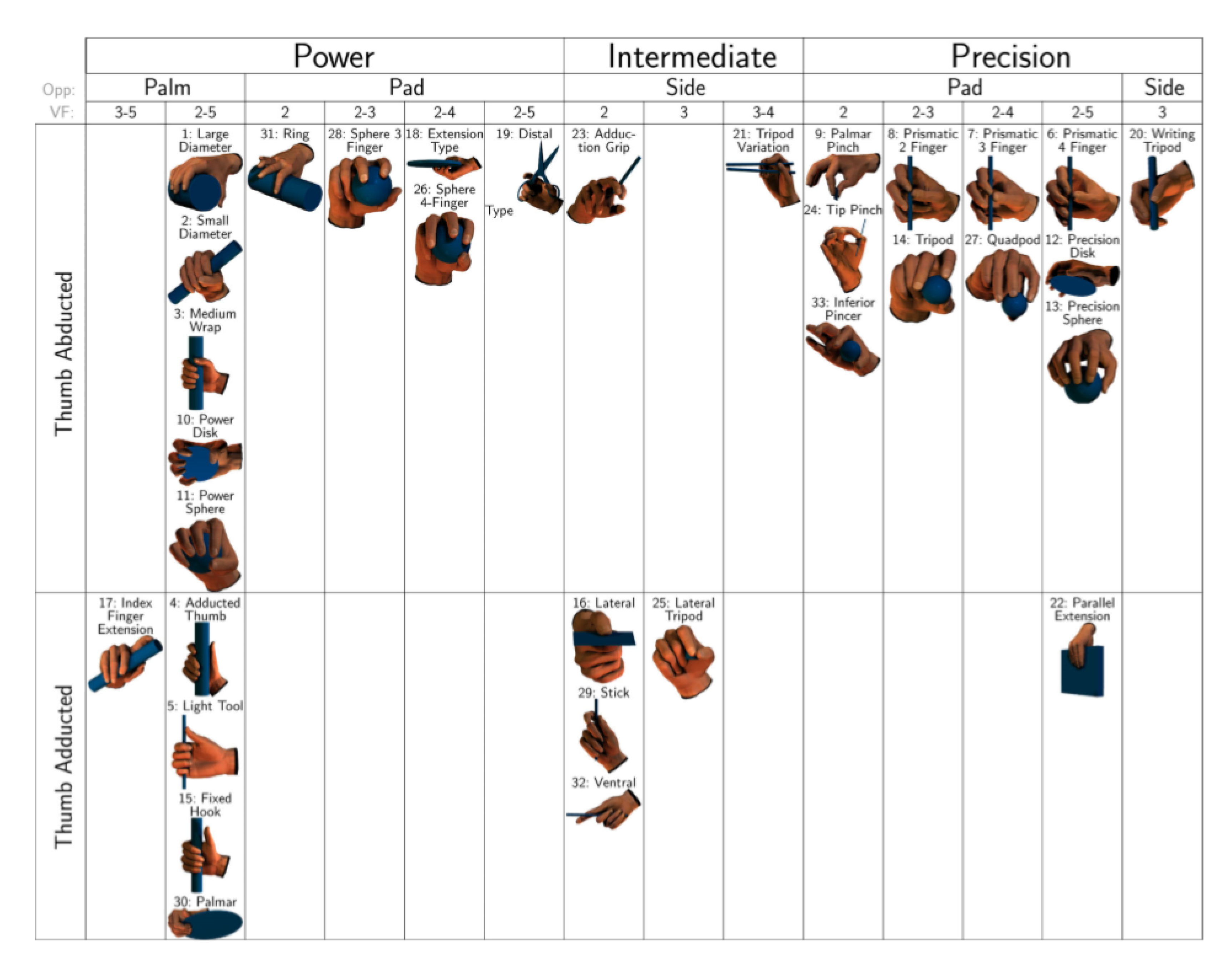
- power, intermediate, and precision grasp;
- type of thumb opposition: palm, pad, and side;
- thumb adduction or abduction; and
- virtual fingers, number of forces applied in different directions.
2.2. Artificial-Hand Examination
3. Construction
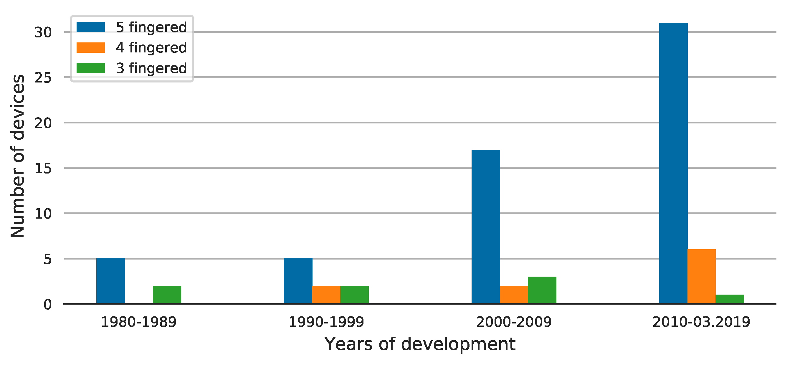
3.1. Finger Configurations
3.2. Joint Types
3.3. Joint Configurations
4. Actuating System
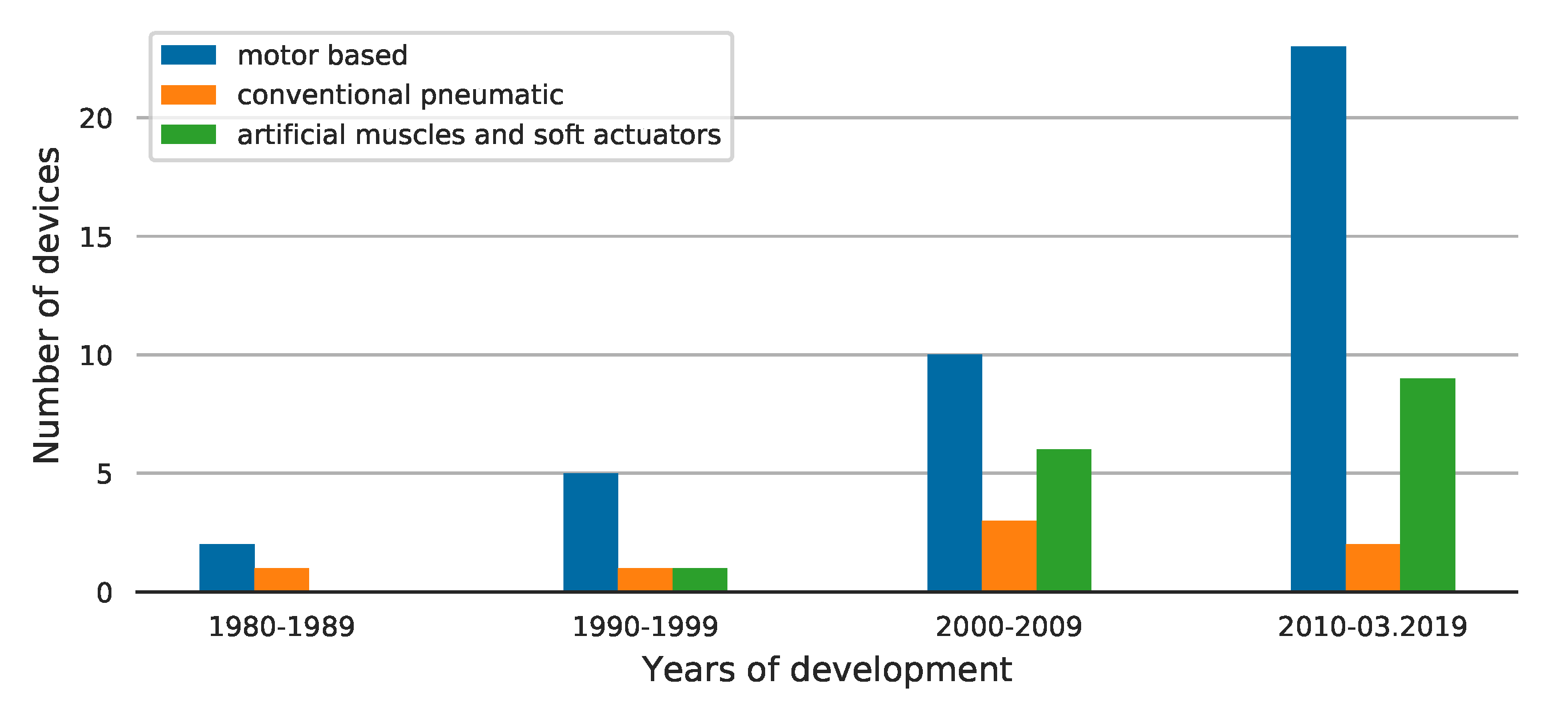
4.1. Actuator Types
4.2. Transmission Approach
4.3. Underactuation and Shape-Adaptive Motion
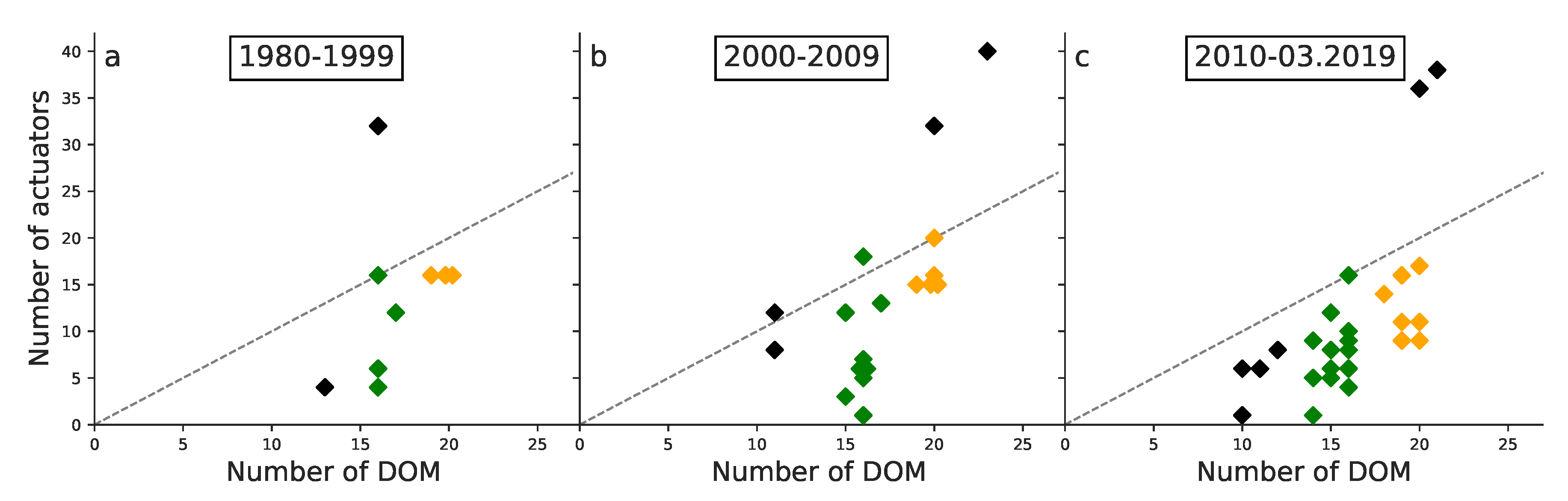
4.4. Number of Actuators
5. Sensors
6. Conclusions
Author Contributions
Funding
Conflicts of Interest
References
- Hwang, J.; Jeong, Y.; Park, J.M.; Lee, K.H.; Hong, J.W.; Choi, J. Biomimetics: Forecasting the future of science, engineering, and medicine. Int. J. Nanomed. 2015, 10, 5701. [Google Scholar] [CrossRef]
- Gebeshuber, I.C.; Stachelberger, H.; Ganji, B.A.; Fu, D.C.; Yunas, J.; Majlis, B.Y. Exploring the innovational potential of biomimetics for novel 3D MEMS. Adv. Mater. Res. 2009, 74, 265–268. [Google Scholar] [CrossRef]
- Vincent, J.F.; Bogatyreva, O.A.; Bogatyrev, N.R.; Bowyer, A.; Pahl, A.K. Biomimetics: Its practice and theory. J. R. Soc. Interface 2006, 3, 471–482. [Google Scholar] [CrossRef] [PubMed]
- Shimomura, M. The New Trends in Next Generation Biomimetics Material Technology: Learning from Biodiversity. Sci. Technol. Trends Q. Rev. 2010, 37, 53–75. [Google Scholar]
- Cho, K.J.; Wood, R. Biomimetic Robots. In Springer Handbook of Robotics; Springer International Publishing: Cham, Switzerland, 2016; pp. 543–574. [Google Scholar]
- Paulson, L.D. Biomimetic Robots. Computer 2004, 37, 48–53. [Google Scholar] [CrossRef]
- Seok, S.; Wang, A.; Chuah, M.Y.; Otten, D.; Lang, J.; Kim, S. Design principles for highly efficient quadrupeds and implementation on the MIT Cheetah robot. In Proceedings of the IEEE International Conference on Robotics and Automation, Karlsruhe, Germany, 6–10 May 2013; pp. 3307–3312. [Google Scholar]
- Kamamichi, N.; Yamakita, M.; Asaka, K.; Luo, Z.W. A snake-like swimming robot using IPMC actuator/sensor. In Proceedings of the IEEE International Conference on Robotics and Automation, Orlando, FL, USA, 15–19 May 2006; Volume 2006, pp. 1812–1817. [Google Scholar]
- Neveln, I.D.; Bai, Y.; Snyder, J.B.; Solberg, J.R.; Curet, O.M.; Lynch, K.M.; MacIver, M.A. Biomimetic and bio-inspired robotics in electric fish research. J. Exp. Biol. 2013, 216, 2501–2514. [Google Scholar] [CrossRef] [PubMed] [Green Version]
- Lin, P.C.; Liu, G.H.; Lin, H.Y.; Lin, H.Y.; Chen, S.T. A Bio-Inspired Hopping Kangaroo Robot with an Active Tail. J. Bionic Eng. 2014, 11, 541–555. [Google Scholar] [CrossRef]
- Ma, K.Y.; Chirarattananon, P.; Fuller, S.B.; Wood, R.J. Controlled flight of a biologically inspired, insect-scale robot. Science 2013, 340, 603–607. [Google Scholar] [CrossRef]
- Lambrecht, B.G.; Horchler, A.D.; Quinn, R.D. A small, insect-inspired robot that runs and jumps. In Proceedings of the IEEE International Conference on Robotics and Automation, Barcelona, Spain, 18–22 April 2005; Volume 2005, pp. 1240–1245. [Google Scholar]
- Dougherty, P.J.; DeMaio, M. Major General Norman T. Kirk and Amputee Care During World War II. Clin. Orthop. Relat. Res. 2014, 472, 3107. [Google Scholar] [CrossRef]
- Watve, S.; Dodd, G.; MacDonald, R.; Stoppard, E.R. Upper limb prosthetic rehabilitation. Orthop. Trauma 2011, 25, 135–142. [Google Scholar] [CrossRef]
- Billock, J.N. Upper Limb Prosthetic Terminal Devices: Hands Versus Hooks. Clin. Prosthetics Orthot. 1986, 10, 57–65. [Google Scholar]
- Huinink, L.H.; Bouwsema, H.; Plettenburg, D.H.; Van der Sluis, C.K.; Bongers, R.M. Learning to use a body-powered prosthesis: Changes in functionality and kinematics. J. Neuroeng. Rehabil. 2016, 13, 90. [Google Scholar] [CrossRef] [PubMed]
- Body-Powered Upper Limb Prostheses|Ottobock Export. Available online: https://www.ottobock-export.com/en/prosthetics/upper-limb/solution-overview/arm-prostheses-body-powered/ (accessed on 30 September 2019).
- Childress, D. Historical Aspects of Powered Limb Prostheses. Clin. Prosthetics Orthot. 1985, 9, 2–13. [Google Scholar]
- Agrawal, S. Hands: Human To Robotic; Technical Report January; University of Pennsylvania: Philadelphia, PA, USA, 1991. [Google Scholar]
- Lovchik, C.; Diftler, M. The Robonaut hand: A dexterous robot hand for space. In Proceedings of the 1999 IEEE International Conference on Robotics & Automation, Detroit, MI, USA, 10–15 May 1999; pp. 907–912. [Google Scholar]
- Crowder, R. A whole arm manipulator for hazardous environments. In Proceedings of the 10th Annual British Robot Association Conference, Birmingham, UK, 12–14 May 1987; pp. 142–153. [Google Scholar]
- Spudis, P.D.; Taylor, G.J. The Roles of Humans and Robots Field Geologists on the Moon. In 2nd Conference on Lunar Bases and Space Activities; Johnson Space Center, NASA: Houston, TX, USA, 1992; pp. 307–313. [Google Scholar]
- Jau, B.M. Dexterous telemanipulation with four fingered hand system. In Proceedings of the IEEE International Conference on Robotics and Automation, Nagoya, Japan, 21–27 May 1995; Volume 1, pp. 338–343. [Google Scholar]
- Ali, M.S.; Engler, C. NASA Technical Memorandum System Description Document for the Anthrobot-2: A Dexterous Robot Hand; Technical report; NASA: Washington, DC, USA, 1991. [Google Scholar]
- Hammock, M.L.; Chortos, A.; Tee, B.C.K.; Tok, J.B.H.; Bao, Z. 25th anniversary article: The evolution of electronic skin (E-Skin): A brief history, design considerations, and recent progress. Adv. Mater. 2013, 25, 5997–6038. [Google Scholar] [CrossRef] [PubMed]
- Hernandez, N.V.; Davila, J.G.; Garza-Ulloa, J.; Rangel, P.; Torres, J.A. Development of a design theory & methodology model for mechatronics. In Proceedings of the ASEE Annual Conference and Exposition, San Antonio, TX, USA, 10–13 June 2012. [Google Scholar]
- Bird, H. Approaches to electronic miniaturization. IEEE Trans. Compon. Packag. Manuf. Technol. Part A 1995, 18, 274–278. [Google Scholar] [CrossRef]
- Yaniger, S. Force Sensing Resistors: A Review Of The Technology. In Proceedings of the Electro International, New York, NY, USA, 16–18 April 1991; pp. 666–668. [Google Scholar]
- Shintake, J.; Piskarev, E.; Jeong, S.H.; Floreano, D. Ultrastretchable Strain Sensors Using Carbon Black-Filled Elastomer Composites and Comparison of Capacitive Versus Resistive Sensors. Adv. Mater. Technol. 2018, 3. [Google Scholar] [CrossRef]
- Ge, J.; Sun, L.; Zhang, F.R.; Zhang, Y.; Shi, L.A.; Zhao, H.Y.; Zhu, H.W.; Jiang, H.L.; Yu, S.H. A Stretchable Electronic Fabric Artificial Skin with Pressure-, Lateral Strain-, and Flexion-Sensitive Properties. Adv. Mater. 2016, 28, 722–728. [Google Scholar] [CrossRef] [PubMed]
- Haines, C.S.; Lima, M.D.; Li, N.; Spinks, G.M.; Foroughi, J.; Madden, J.D.; Kim, S.H.; Fang, S.; De Andrade, M.J.; Göktepe, F.; et al. Artificial muscles from fishing line and sewing thread. Science 2014, 343, 868–872. [Google Scholar] [CrossRef]
- Brochu, P.; Pei, Q. Advances in Dielectric Elastomers for Actuators and Artificial Muscles. Macromol. Rapid Commun. 2010, 31, 10–36. [Google Scholar] [CrossRef] [PubMed]
- Kumar, P.; Lagoudas, D. Introduction to Shape Memory Alloys. In Metal and Ceramic Biomaterials: Volume II Strength and Surface; CRC Press: Boca Raton, FL, USA, 2008; pp. 63–90. [Google Scholar]
- Shintake, J.; Rosset, S.; Schubert, B.; Floreano, D.; Shea, H. Versatile Soft Grippers with Intrinsic Electroadhesion Based on Multifunctional Polymer Actuators. Adv. Mater. 2016, 28, 231–238. [Google Scholar] [CrossRef]
- Shintake, J.; Cacucciolo, V.; Floreano, D.; Shea, H. Soft Robotic Grippers. Adv. Mater. 2018, 30, 1707035. [Google Scholar] [CrossRef] [PubMed]
- Kawasaki, H.; Komatsu, T.; Uchiyama, K. Dexterous anthropomorphic robot hand with distributed tactile sensor: Gifu hand II. IEEE/ASME Trans. Mech. 2002, 7, 296–303. [Google Scholar] [CrossRef]
- Cho, K.J.; Rosmarin, J.; Asada, H. SBC hand: A lightweight robotic hand with an SMA actuator array implementing C-segmentation. In Proceedings of the IEEE International Conference on Robotics and Automation, Roma, Italy, 10–14 April 2007; pp. 921–926. [Google Scholar]
- Jacobsen, S.; Johnson, R.; Biggers, K.; Iversen, E.; Knutti, D. Design of the Utah/M.I.T. Dextrous Hand. In Proceedings of the 1986 IEEE International Conference on Robotics and Automation, San Francisco, CA, USA, 7–10 April 1986; Volume 3, pp. 1520–1532. [Google Scholar]
- Yoshikawa, M.; Sato, R.; Higashihara, T.; Ogasawara, T.; Kawashima, N. Rehand: Realistic electric prosthetic hand created with a 3D printer. In Proceedings of the Annual International Conference of the IEEE Engineering in Medicine and Biology Society, Milano, Italy, 25–29 August 2015; Volume 40, pp. 2470–2473. [Google Scholar]
- You, W.S.; Lee, Y.H.; Oh, H.S.; Kang, G.; Choi, H.R. Design of a 3D-printable, robust anthropomorphic robot hand including intermetacarpal joints. Intell. Serv. Robot. 2019, 12, 1–16. [Google Scholar] [CrossRef]
- Kawamura, K.; Wilkes, D.M.; Kawamura, K.; Pack, T.; Bishay, M.; Barile, J. Humanoids: Future robots for home and factory Quantitative assessment of sensory function in high-risk infants and children View project Array Processing View project Humanoids: Future Robots for Home and Factory. In Proceedings of the First International Symposium on Humanoid Robots, Tokyo, Japan, 30–31 October 1996; pp. 53–62. [Google Scholar]
- Cresswell, K.; Cunningham-Burley, S.; Sheikh, A. Health care robotics: Qualitative exploration of key challenges and future directions. J. Med. Internet Res. 2018, 20. [Google Scholar] [CrossRef] [PubMed]
- Huntsberger, T.; Rodriguez, G.; Schenker, P.S. Robotics challenges for robotic and human Mars exploration. In Proceedings of the 4th International Conference and Exposition on Robotics for Challenging Situations and Environments—Robotics 2000, Albuquerque, NM, USA, 27 February–2 March 2000; Volume 299, pp. 340–346. [Google Scholar]
- Landis, G.A. Robots and humans: Synergy in planetary exploration. Acta Astronaut. 2004, 55, 985–990. [Google Scholar] [CrossRef] [PubMed]
- Takanishi, A.; Cabibihan, J.; Matsumoto, M.; Dario, P.; Roccella, S.; Zecca, M.; Carrozza, M.; Ltoh, K.; Cappiello, G.; Miwa, H. Design, fabrication and preliminary results of a novel anthropomorphic hand for humanoid robotics: RCH-1. In Proceedings of the 2004 IEEE/RSJ International Conference on Intelligent Robots and Systems, Sendai, Japan, 28 September–2 October 2004; Volime 1, pp. 266–271. [Google Scholar]
- Broadbent, E.; Stafford, R.; MacDonald, B. Acceptance of healthcare robots for the older population: Review and future directions. Int. J. Soc. Robot. 2009, 1, 319–330. [Google Scholar] [CrossRef]
- Joseph, A.; Christian, B.; Abiodun, A.A.; Oyawale, F. A review on humanoid robotics in healthcare. In Proceedings of the MATEC Web of Conferences, Kuala Lumpur, Malaysia, 28–30 November 2017; Volume 153, p. 02004. [Google Scholar]
- Szkopek, J. Comparison of Artificial Hands Developed in Years 1980–2019. Available online: https://doi.org/10.5281/zenodo.3360259 (accessed on 30 September 2019).
- Netter, F.H. Atlas of Human Anatomy; Saunders/Elsevier: Amsterdam, The Netherlands, 2014. [Google Scholar]
- Komatsu, I.; Lubahn, J.D. Anatomy and Biomechanics of the Thumb Carpometacarpal Joint. Oper. Tech. Orthop. 2018, 28, 1–5. [Google Scholar] [CrossRef]
- Levangie, P.K.; Norkin, C.C. Joint Structure and Function: A Comprehensive Analysis; F.A. Davis Company: Philadelphia, PA, USA, 2011; p. 320. [Google Scholar]
- Parida, P.K.; Biswal, B.B. Design and Analysis of a Multifingered Robot Hand. IAES Int. J. Robot. Autom. (IJRA) 2012, 1. [Google Scholar] [CrossRef]
- Peña-Pitarch, E.; Falguera, N.T.; Yang, J.J. Virtual human hand: Model and kinematics. Comput. Methods Biomech. Biomed. Eng. 2014, 17, 568–579. [Google Scholar] [CrossRef]
- Krans, J.L. How Do Muscles Contract? What Molecules Are Necessary for a Tissue to Change Its Shape? Available online: https://www.nature.com/scitable/topicpage/the-sliding-filament-theory-of-muscle-contraction-14567666 (accessed on 28 June 2019).
- Hansen, J.T.; Koeppen, B.M. Netter’s Atlas of Human Physiology; Saunders: Philadelphia, PA, USA, 2002. [Google Scholar]
- Hu, D.; Howard, D.; Ren, L. Biomechanical analysis of the human finger extensor mechanism during isometric pressing. PLoS ONE 2014, 9. [Google Scholar] [CrossRef]
- Chappell, P.H.; Cranny, A.; Cotton, D.P.; White, N.M.; Beeby, S.P. Sensory motor systems of artificial and natural hands. Int. J. Surg. 2007, 5, 436–440. [Google Scholar] [CrossRef] [PubMed] [Green Version]
- Abraira, V.E.; Ginty, D.D. The Sensory Neurons of Touch. Neuron 2013, 79, 618–639. [Google Scholar] [CrossRef] [PubMed] [Green Version]
- Owens, D.M.; Lumpkin, E.A. Diversification and specialization of touch receptors in skin. Cold Spring Harb. Perspect. Med. 2014, 4. [Google Scholar] [CrossRef]
- Silvera-Tawil, D.; Rye, D.; Velonaki, M. Artificial skin and tactile sensing for socially interactive robots: A review. Robot. Auton. Syst. 2015, 63, 230–243. [Google Scholar] [CrossRef]
- Napier, J.R. The prehensile movements of the human hand. J. Bone Jt. Surgery. Br. Vol. 1956, 38, 902–913. [Google Scholar] [CrossRef]
- Cutkosky, M.R. On Grasp Choice, grasp Models, and the Design of Hands for Manufacturing Tasks. IEEE Trans. Robot. Autom. 1989, 5, 269–279. [Google Scholar] [CrossRef]
- Feix, T.; Romero, J.; Schmiedmayer, H.B.; Dollar, A.M.; Kragic, D. The GRASP Taxonomy of Human Grasp Types. IEEE Trans. Hum. Mach. Syst. 2016, 46. [Google Scholar] [CrossRef]
- Light, C.M.; Chappell, P.H.; Kyberd, P.J. Establishing a standardized clinical assessment tool of pathologic and prosthetic hand function: Normative data, reliability, and validity. Arch. Phys. Med. Rehabil. 2002, 83, 776–783. [Google Scholar] [CrossRef] [Green Version]
- Vazhapilli Sureshbabu, A.; Metta, G.; Parmiggiani, A. A Systematic Approach to Evaluating and Benchmarking Robotic Hands—The FFP Index. Robotics 2019, 8, 7. [Google Scholar] [CrossRef]
- Biagiotti, L.; Lotti, F.; Melchiorri, C.; Vassura, G. How Far Is the Human Hand? Technical Report; University of Bologna: Bologna, Italy, 2004. [Google Scholar]
- Murray, R.M.; Li, Z.; Sastry, S.S. A Mathematical Introduction to Robotic Manipulation; CRC Press: Boca Raton, FL, USA, 1994; Volume 29, pp. 214–222. [Google Scholar]
- Childress, D.; Strysik, J. Myoelectrically Controlled Artificial Hand. U.S. Patent No 4,623,354, 18 November 1986. [Google Scholar]
- Loncaric, J.; de Comarmond, F.; Bartusek, J.; Pati, Y.; Tsakiris, D.; Yang, R. Modular Dextrous Hand; Technical Report; The University of Maryland: College Park, MD, USA, 1989. [Google Scholar]
- Monestier, J. Total Hand Prostheses. U.S. Patent No 4,685,929, 11 August 1987. [Google Scholar]
- Kargov, A.; Asfour, T.; Pylatiuk, C.; Oberle, R.; Klosek, H.; Schulz, S.; Regenstein, K.; Bretthauer, G.; Dillman, R. Development of an anthropomorphic hand for a mobile assistive robot. In Proceedings of the 2005 IEEE 9th International Conference on Rehabilitation Robotics, Chicago, IL, USA, 28 June–1 July 2005; pp. 182–186. [Google Scholar]
- Dalley, S.A.; Wiste, T.E.; Withrow, T.J.; Goldfarb, M. Design of a multifunctional anthropomorphic prosthetic hand with extrinsic actuation. IEEE/ASME Trans. Mech. 2009, 14, 699–706. [Google Scholar] [CrossRef]
- Paik, J.K.; Shin, B.H.; Bang, Y.b.; Shim, Y.B. Development of an Anthropomorphic Robotic Arm and Hand for Interactive Humanoids. J. Bionic Eng. 2012, 9, 133–142. [Google Scholar] [CrossRef]
- Okada, T. Computer Control Of Multijointed Finger System For Precise Object-Handling. IEEE Trans. Syst. Man Cybern. 1982, 12, 289–299. [Google Scholar] [CrossRef]
- Loucks, C.; Starr, G.; Johnson, V.; Steele, J.; Boissiere, P. Modeling and control of the stanford/JPL hand. In Proceedings of the 1987 IEEE International Conference on Robotics and Automation, Raleigh, NC, USA, 31 March–3 April 1987; Volume 4, pp. 573–578. [Google Scholar]
- Guo, G.; Gruver, W.A.; Qian, X. A New Design for a Dextrous Robotic Hand Mechanism. IEEE Control Syst. 1992, 12, 35–38. [Google Scholar] [CrossRef]
- Crisman, J.D.; Kanojia, C.; Zeid, I. Graspar: A flexible, easily controllable robotic hand. IEEE Robot. Autom. Mag. 1996, 3, 32–38. [Google Scholar] [CrossRef]
- Jung, S.Y.; Kang, S.K.; Lee, M.J.; Moon, I. Design of robotic hand with tendon-driven three fingers. In Proceedings of the ICCAS 2007—International Conference on Control, Automation and Systems, Seoul, Korea, 17–20 October 2007; pp. 83–86. [Google Scholar]
- Zollo, L.; Roccella, S.; Guglielmelli, E.; Carrozza, M.C.; Dario, P. Biomechatronic design and control of an anthropomorphic artificial hand for prosthetic and robotic applications. IEEE/ASME Trans. Mech. 2007, 12, 418–429. [Google Scholar] [CrossRef]
- Price, A.D.; Jnifene, A.; Naguib, H.E. Design and control of a shape memory alloy based dexterous robot hand. Smart Mater. Struct. 2007, 16, 1401–1414. [Google Scholar] [CrossRef]
- Wang, L.; DelPreto, J.; Bhattacharyya, S.; Weisz, J.; Allen, P.K. A highly-underactuated robotic hand with force and joint angle sensors. In Proceedings of the IEEE International Conference on Intelligent Robots and Systems, San Francisco, CA, USA, 25–30 September 2011; pp. 1380–1385. [Google Scholar]
- Jau, B. Anthropomorphic Four Fingered Robot Hand And Its Glove Controller. In Proceedings of the Twelfth Annual International Conference of the IEEE Engineering in Medicine and Biology Society, Philadelphia, PA, USA, 1–4 November 1990; pp. 1940–1941. [Google Scholar]
- Ramos, A.M.; Gravagne, I.A.; Walker, I.D. Goldfinger: A non-anthropomorphic, dextrous robot hand. In Proceedings of the IEEE International Conference on Robotics and Automation, Detroit, MI, USA, 10–15 May 1999; Volume 2, pp. 913–919. [Google Scholar]
- Figliolini, G.; Rea, P. Ca.U.M.Ha. robotic hand (cassino-underactuated-multifinger-hand). In Proceedings of the IEEE/ASME International Conference on Advanced Intelligent Mechatronics, Zurich, Switzerland, 4–7 September 2007. [Google Scholar]
- Kaneko, K.; Harada, K.; Kanehiro, F. Development of multi-fingered hand for life-size humanoid robots. In Proceedings of the IEEE International Conference on Robotics and Automation, Pasadena, CA, USA, 14 September 2007; Volume 26, pp. 913–920. [Google Scholar]
- Takeuchi, H.; Watanabe, T. Development of a multi-fingered robot hand with softness changeable skin mechanism. In Proceedings of the ISR 2010 (41st International Symposium on Robotics) and ROBOTIK 2010 (6th German Conference on Robotics), Munich, Germany, 7–9 June 2010. [Google Scholar]
- Nagase, J.Y.; Wakimoto, S.; Satoh, T.; Saga, N.; Suzumori, K. Design of a variable-stiffness robotic hand using pneumatic soft rubber actuators. Smart Mater. Struct. 2011, 20. [Google Scholar] [CrossRef]
- Kim, E.H.; Lee, S.W.; Lee, Y.K. A dexterous robot hand with a bio-mimetic mechanism. Int. J. Precis. Eng. Manuf. 2011, 12, 227–235. [Google Scholar] [CrossRef]
- Mnyusiwalla, H.; Vulliez, P.; Gazeau, J.P.; Zeghloul, S. A New Dexterous Hand Based on Bio-Inspired Finger Design for Inside-Hand Manipulation. IEEE Trans. Syst. Man Cybern. Syst. 2016, 46, 809–817. [Google Scholar] [CrossRef]
- Lee, D.H.; Park, J.H.; Park, S.W.; Baeg, M.H.; Bae, J.H. KITECH-Hand: A Highly Dexterous and Modularized Robotic Hand. IEEE/ASME Trans. Mech. 2017, 22, 876–887. [Google Scholar] [CrossRef]
- Vinogradov, O. Fundamentals of Kinematics and Dynamics of Machines and Mechanisms; CRC Press: Boca Raton, FL, USA, 2000; pp. 6–7. [Google Scholar]
- Vande Weghe, M.; Rogers, M.; Weissert, M.; Matsuoka, Y. The ACT Hand: Design of the skeletal structure. In Proceedings of the International Conference on Robotics & Automation, Kunming, China, 6–9 December 2004; pp. 3375–3379. [Google Scholar]
- Xu, Z.; Kumar, V.; Matsuoka, Y.; Todorov, E. Design of an anthropomorphic robotic finger system with biomimetic artificial joints. In Proceedings of the IEEE RAS and EMBS International Conference on Biomedical Robotics and Biomechatronics, Rome, Italy, 24–27 June 2012; pp. 568–574. [Google Scholar]
- Controzzi, M.; Cipriani, C.; Jehenne, B.; Donati, M.; Carrozza, M.C. Bio-inspired mechanical design of a tendon-driven dexterous prosthetic hand. In Proceedings of the 2010 Annual International Conference of the IEEE Engineering in Medicine and Biology, Buenos Aires, Argentina, 31 August–4 September 2010; pp. 499–502. [Google Scholar]
- Grebenstein, M.; Chalon, M.; Hirzinger, G.; Siegwart, R. Antagonistically driven finger design for the anthropomorphic DLR hand arm system. In Proceedings of the 2010 10th IEEE-RAS International Conference on Humanoid Robots, Nashville, TN, USA, 6–8 December 2010; pp. 609–616. [Google Scholar]
- Engler, C.D. Design and Development of an Anthropomorphic Electro-Mechanical Hand with Exoskeletal Control for Reproduction of Human Hand Dexterity. Ph.D. Thesis, Lehigh University, Bethlehem, PA, USA, 1988. [Google Scholar]
- Schectman, L.A. Artificial Robotic Hand. U.S. Patent No 5,080,682, 14 January 1992. [Google Scholar]
- Cho, K.J.; Rosemarin, J.; Asada, H. Design of vast DOF artificial muscle actuators with a cellular array structure and its application to a five-fingered robotic hand. In Proceedings of the IEEE International Conference on Robotics and Automation, Orlando, FL, USA, 15–19 May 2006; pp. 2214–2219. [Google Scholar]
- Liu, H.; Wu, K.; Meusel, P.; Seitz, N.; Hirzinger, G.; Jin, M.; Liu, Y.; Fan, S.; Lan, T.; Chen, Z. Multisensory five-finger dexterous hand: The DLR/HIT Hand II. In Proceedings of the 2008 IEEE/RSJ International Conference on Intelligent Robots and Systems, Nice, France, 22–26 September 2008; pp. 3692–3697. [Google Scholar]
- Xu, Z.; Kumar, V.; Todorov, E. A low-cost and modular, 20-DOF anthropomorphic robotic hand: Design, actuation and modeling. In Proceedings of the IEEE-RAS International Conference on Humanoid Robots, Atlanta, GA, USA, 15–17 October 2013; Volume 13, pp. 368–375. [Google Scholar]
- Peregrina, M.A.; Poveda, A.R. Design and development of an open antropomorphic robotic hand development system. In Proceedings of the 2018 IEEE International Conference on Cyborg and Bionic Systems (CBS), Shenzhen, China, 25–27 October 2018; pp. 592–596. [Google Scholar]
- Bundhoo, V.; Park, E.J. Design of an artificial muscle actuated finger towards biomimetic prosthetic hands. In Proceedings of the 12th International Conference on Advanced Robotics, Seattle, WA, USA, 18–20 July 2005; Volume 2005, pp. 368–375. [Google Scholar]
- Çulha, U.; Iida, F. Enhancement of finger motion range with compliant anthropomorphic joint design. Bioinspir. Biomim. 2016, 11. [Google Scholar] [CrossRef] [PubMed]
- Deimel, R.; Brock, O. A novel type of compliant and underactuated robotic hand for dexterous grasping. Int. J. Robot. Res. 2016, 35, 161–185. [Google Scholar] [CrossRef]
- Qi, P.; Bai, Y.; Yang, N.; Xu, Z.; Ni, R.; Sun, Y. Anthropomorphic Soft Pneumatic Fingers Towards Full Dexterity of Human Hand. In Proceedings of the 2018 IEEE-RAS 18th International Conference on Humanoid Robots (Humanoids), Beijing, China, 6–9 November 2018; pp. 381–386. [Google Scholar]
- Tavakoli, M.; De Almeida, A.T. Adaptive under-actuated anthropomorphic hand: ISR-SoftHand. In Proceedings of the IEEE International Conference on Intelligent Robots and Systems, Chicago, IL, USA, 14–18 September 2014; pp. 1629–1634. [Google Scholar]
- Kontoudis, G.P.; Liarokapis, M.V.; Zisimatos, A.G.; Mavrogiannis, C.I.; Kyriakopoulos, K.J. Open-source, anthropomorphic, underactuated robot hands with a selectively lockable differential mechanism: Towards affordable prostheses. In Proceedings of the IEEE International Conference on Intelligent Robots and Systems, Hamburg, Germany, 28 September–2 October 2015; Volume 40, pp. 5857–5862. [Google Scholar]
- Lotti, F.; Tiezzi, P.; Vassura, G.; Biagiotti, L.; Palli, G.; Melchiorri, C. Development of UB Hand 3: Early results. In Proceedings of the IEEE International Conference on Robotics and Automation, Barcelona, Spain, 18–22 April 2005; pp. 4488–4493. [Google Scholar]
- LI, G.; LIU, H.; ZHANG, W. Development of Multi-Fingered Robotic Hand With Coupled and Directly Self-Adaptive Grasp. Int. J. Hum. Robot. 2012, 9. [Google Scholar] [CrossRef]
- Lee, Y.K.; Shimoyama, I. A skeletal framework artificial hand actuated by pneumatic artificial muscles. Adv. Robot. 1998, 13, 349–350. [Google Scholar] [CrossRef]
- Yamano, I.; Maeno, T. Five-fingered robot hand using ultrasonic motors and elastic elements. In Proceedings of the IEEE International Conference on Robotics and Automation, Barcelona, Spain, 18–22 April 2005; pp. 2673–2678. [Google Scholar]
- Nasser, S.; Rincon, D.; Rodriguez, M. Design of an anthropomorphic underactuated hand prosthesis with passive-adaptive grasping capabilities. In Proceedings of the Florida Conf. on Recent Advances in Robotics and Robot Showcase, Miami, FL, USA, 25–26 May 2006. [Google Scholar]
- Saharan, L.; Tadesse, Y. Robotic hand with locking mechanism using TCP muscles for applications in prosthetic hand and humanoids. Bioinspir. Biomim. Bioreplication 2016, 9797. [Google Scholar] [CrossRef]
- Nemoto, Y.; Ogawa, K.; Yoshikawa, M. F3Hand: A Five-Fingered Prosthetic Hand Driven with Curved Pneumatic Artificial Muscles. In Proceedings of the Annual International Conference of the IEEE Engineering in Medicine and Biology Society, EMBS, Honolulu, HI, USA, 18–21 July 2018; pp. 1668–1671. [Google Scholar]
- Kim, K.R.; Jeong, S.H.; Kim, P.; Kim, K.S. Design of Robot Hand With Pneumatic Dual-Mode Actuation Mechanism Powered by Chemical Gas Generation Method. IEEE Robot. Autom. Lett. 2018, 3, 4193–4200. [Google Scholar] [CrossRef]
- Nisal, K.; Ruhunge, I.; Subodha, J.; Perera, C.J.; Lalitharatne, T.D. Design, implementation and performance validation of UOMPro artificial hand: Towards affordable hand prostheses. In Proceedings of the Annual International Conference of the IEEE Engineering in Medicine and Biology Society, EMBS, Seogwipo, Korea, 11–15 July 2017; pp. 909–912. [Google Scholar]
- Wu, L.; Jung De Andrade, M.; Saharan, L.K.; Rome, R.S.; Baughman, R.H.; Tadesse, Y. Compact and low-cost humanoid hand powered by nylon artificial muscles. Bioinspir. Biomim. 2017, 12. [Google Scholar] [CrossRef] [PubMed]
- Lovchik, C.; Aldridge, H.; Diftler, M. Design of the NASA Robonaut Hand; Technical Report; NASA: Washington, DC, USA, 1999. [Google Scholar]
- Xiong, C.H.; Chen, W.R.; Sun, B.Y.; Liu, M.J.; Yue, S.G.; Chen, W.B. Design and Implementation of an Anthropomorphic Hand for Replicating Human Grasping Functions. IEEE Trans. Robot. 2016, 32, 652–671. [Google Scholar] [CrossRef]
- Tsujiuchi, N.; Koizumi, T.; Nishino, S.; Komatsubara, H.; Kudawara, T.; Hirano, M. Development of Pneumatic Robot Hand and Construction of Master-Slave System. J. Syst. Des. Dyn. 2008, 2, 1306–1315. [Google Scholar] [CrossRef] [Green Version]
- Carrozza, M.C.; Cappiello, G.; Micera, S.; Edin, B.B.; Beccai, L.; Cipriani, C. Design of a cybernetic hand for perception and action. Biol. Cybern. 2006, 95, 629–644. [Google Scholar] [CrossRef] [Green Version]
- Mahmoud, R.; Ueno, A.; Tatsumi, S. Dexterous mechanism design for an anthropomorphic artificial hand: Osaka City University Hand I. In Proceedings of the 2010 10th IEEE-RAS International Conference on Humanoid Robots, Nashville, TN, USA, 6–8 December 2010; pp. 180–185. [Google Scholar]
- Grebenstein, M.; Albu-Schäffer, A.; Bahls, T.; Chalon, M.; Eiberger, O.; Friedl, W.; Gruber, R.; Haddadin, S.; Hagn, U.; Haslinger, R.; et al. The DLR hand arm system. In Proceedings of the IEEE International Conference on Robotics and Automation, Shanghai, China, 9–13 May 2011; pp. 3175–3182. [Google Scholar]
- Yi, S.H. Electronic Artificial Hand. US Patent 0303633; filed 28 June 2018, and issued 25 October 2018,
- El Kady, A.M.; Mahfouz, A.E.; Taher, M.F. Mechanical design of an anthropomorphic prosthetic hand for shape memory alloy actuation. In Proceedings of the 2010 5th Cairo International Biomedical Engineering Conference, Cairo, Egypt, 16–18 December 2010; pp. 86–89. [Google Scholar]
- Lee, J.H.; Okamoto, S.; Matsubara, S. Development of Multi-Fingered Prosthetic Hand Using Shape Memory Alloy Type Artificial Muscle. Comput. Technol. Appl. 2012, 3, 477–484. [Google Scholar]
- Gaiser, I.; Schulz, S.; Kargov, A.; Klosek, H.; Bierbaum, A.; Pylatiuk, C.; Oberle, R.; Werner, T.; Asfour, T.; Bretthauer, G.; et al. A new anthropomorphic robotic hand. In Proceedings of the 2008 8th IEEE-RAS International Conference on Humanoid Robots, Daejeon, Korea, 1–3 December 2008; pp. 418–422. [Google Scholar]
- Zhang, Z.; Han, T.; Pan, J.; Wang, Z. CATCH-919 Hand: Design of a 9-actuator 19-DOF Anthropomorphic Robotic Hand. arXiv 2018, arXiv:1809.04290. [Google Scholar]
- Belter, J.T.; Dollar, A.M. Performance characteristics of anthropomorphic prosthetic hands. In Proceedings of the IEEE International Conference on Rehabilitation Robotics, Zurich, Switzerland, 29 June–1 July 2011. [Google Scholar]
- Belter, J.T.; Segil, J.L.; Dollar, A.M.; Weir, R.F. Mechanical design and performance specifications of anthropomorphic prosthetic hands: A review. J. Rehabil. Res. Dev. 2013, 50, 599–618. [Google Scholar] [CrossRef] [PubMed]
- Röthling, F.; Haschke, R.; Steil, J.J.; Ritter, H. Platform portable anthropomorphic grasping with the Bielefeld 20-DOF Shadow and 9-DOF TUM Hand. In Proceedings of the IEEE International Conference on Intelligent Robots and Systems, San Diego, CA, USA, 29 October–2 November 2007; pp. 2951–2956. [Google Scholar]
- Controzzi, M.; Cipriani, C.; Carrozza, M.C. Design of artificial hands: A review. Springer Tracts Adv. Robot. 2014, 95, 219–246. [Google Scholar] [CrossRef]
- Lai, J.C.; Schoen, M.P.; Perez Gracia, A.; Naidu, D.S.; Leung, S.W. Prosthetic devices: Challenges and implications of robotic implants and biological interfaces. Proc. Inst. Mech. Eng. Part H J. Eng. Med. 2007, 221, 173–183. [Google Scholar] [CrossRef] [PubMed]
- Weir, R.F. Design of artificial arms and hands for prosthetic applications. In Standard Handbook of Biomedical Engineering & Design; McGraw-Hill: New York, NY, USA, 2003; pp. 32.1–32.61. [Google Scholar]
- Del Cura, V.O.; Cunha, F.L.; Aguiar, M.L.; Cliquet, A. Study of the different types of actuators and mechanisms for upper limb prostheses. Artif. Organs 2003, 27, 507–516. [Google Scholar] [CrossRef]
- Redman, T.R. The Design of a Robotic Hand with Multiple Actuators for Children. Ph.D. Thesis, University of Southampton, Southampton, UK, 2016. [Google Scholar]
- Kim, Y.J.; Lee, Y.; Kim, J.; Lee, J.W.; Park, K.M.; Roh, K.S.; Choi, J.Y. RoboRay hand: A highly backdrivable robotic hand with sensorless contact force measurements. In Proceedings of the IEEE International Conference on Robotics and Automation, Hong Kong, China, 31 May–7 June 2014; pp. 6712–6718. [Google Scholar]
- Thayer, N.; Priya, S. Design and implementation of a dexterous anthropomorphic robotic typing (DART) hand. Smart Mater. Struct. 2011, 20. [Google Scholar] [CrossRef] [Green Version]
- Yang, D.P.; Zhao, J.D.; Gu, Y.K.; Wang, X.Q.; Li, N.; Jiang, L.; Liu, H.; Huang, H.; Zhao, D.W. An Anthropomorphic Robot Hand Developed Based on Underactuated Mechanism and Controlled by EMG Signals. J. Bionic Eng. 2009, 6, 255–263. [Google Scholar] [CrossRef]
- Sonoda, T.; Godler, I. Multi-fingered robotic hand employing strings transmission named “twist drive”. In Proceedings of the 2010 IEEE/RSJ International Conference on Intelligent Robots and Systems, Taipei, Taiwan, 18–22 October 2010; pp. 2733–2738. [Google Scholar]
- Tondu, B. Modelling of the McKibben artificial muscle: A review. J. Intell. Mater. Syst. Struct. 2012, 23, 225–253. [Google Scholar] [CrossRef]
- Miertsch, L.; Bannasch, R.; Schwenk, H.; Schulz, A.; Boblan, I.; Prietzel, F. A Human-Like Robot Hand and Arm with Fluidic Muscles: Biologically Inspired Construction and Functionality. In Embodied Artificial Intelligence; Springer: Berlin/Heidelberg, Germany, 2010; pp. 160–179. [Google Scholar]
- Pfeiffer, C.; DeLaurentis, K.; Mavroidis, C. Shape memory alloy actuated robot prostheses: Initial experiments. In Proceedings of the 1999 IEEE International Conference on Robotics and Automation (Cat. No.99CH36288C), Detroit, MI, USA, 10–15 May 1999; Volume 3, pp. 2385–2391. [Google Scholar]
- Lafontaine, S.; Hunter, I.; Wieringa, P.; Vandesteeg, N.; Madden, P.; Takshi, A.; Madden, J.; Anquetil, P.; Pytel, R. Artificial Muscle Technology: Physical Principles and Naval Prospects. IEEE J. Ocean. Eng. 2004, 29, 706–728. [Google Scholar] [CrossRef]
- Mirvakili, S.M.; Hunter, I.W. Artificial Muscles: Mechanisms, Applications, and Challenges. Adv. Mater. 2018, 30. [Google Scholar] [CrossRef] [PubMed]
- Delaurentis, K.J.; Mavroidis, C.; Pfeiffer, C.; Technologies, C.; River, T. Development of a Shape Memory Alloy Actuated Robotic Hand. In Proceedings of the 7th International Conference on New Actuators (ACTUATOR 2000), Bremen, Germany, 19–21 June 2000. [Google Scholar]
- Bundhoo, V.; Haslam, E.; Birch, B.; Park, E.J. A shape memory alloy-based tendon-driven actuation system for biomimetic artificial fingers, part I: Design and evaluation. Robotica 2009, 27, 131–146. [Google Scholar] [CrossRef]
- Atasoy, A.; Kaya, E.; Toptas, E.; Kuchimov, S.; Kaplanoglu, E.; Ozkan, M. 24 DOF EMG controlled hybrid actuated prosthetic hand. In Proceedings of the Annual International Conference of the IEEE Engineering in Medicine and Biology Society, EMBS, Orlando, FL, USA, 16–20 August 2016; pp. 5059–5062. [Google Scholar]
- Andrianesis, K.; Tzes, A. Design of an anthropomorphic prosthetic hand driven by shape memory alloy actuators. In Proceedings of the 2nd Biennial IEEE/RAS-EMBS International Conference on Biomedical Robotics and Biomechatronics, Scottsdale, AZ, USA, 19–22 October 2008; pp. 517–522. [Google Scholar]
- Kaplanoglu, E. Design of shape memory alloy-based and tendon-driven actuated fingers towards a hybrid anthropomorphic prosthetic hand. Int. J. Adv. Robot. Syst. 2012, 9. [Google Scholar] [CrossRef]
- He, Z.H.; Bottinelli, R.; Pellegrino, M.A.; Ferenczi, M.A.; Reggiani, C. ATP consumption and efficiency of human single muscle fibers with different myosin isoform composition. Biophys. J. 2000, 79, 945–961. [Google Scholar] [CrossRef]
- Hunter, I.; Lafontaine, S. A comparison of muscle with artificial actuators. In Proceedings of the Technical Digest IEEE Solid-State Sensor and Actuator Workshop, Hilton Head Island, SC, USA, 22–25 June 1992; pp. 178–185. [Google Scholar]
- Barclay, C.J. Energy demand and supply in human skeletal muscle. J. Muscle Res. Cell Motil. 2017, 38, 143–155. [Google Scholar] [CrossRef] [PubMed]
- Muscle Isometric Contraction—An Overview|ScienceDirect Topics. Available online: https://www.sciencedirect.com/topics/medicine-and-dentistry/muscle-isometric-contraction (accessed on 24 May 2019).
- Properties of SMA Material from SmartWires company. Available online: https://smartwires.eu/index.php?controller=cms&id_cms_category=2 (accessed on 30 September 2019).
- Properties of SMA Material from Dynalloy company. Available online: http://www.dynalloy.com/tech_data_wire.php (accessed on 30 September 2019).
- Sheng, J.; Chen, H.; Qiang, J.; Li, B.; Wang, Y. Thermal, Mechanical, and Dielectric Properties of a Dielectric Elastomer for Actuator Applications. J. Macromol. Sci. Part B 2012, 51, 2093–2104. [Google Scholar] [CrossRef]
- La, T.G.; Lau, G.K. Enhanced dielectric strength and actuation of acrylic elastomer with silicone gel encapsulation. In Electroactive Polymer Actuators and Devices (EAPAD) 2016; International Society for Optics and Photonics: Bellingham, WA, USA, 2016. [Google Scholar]
- Major, A.; Project, Q.; Hunt, W. Polymer Artificial Muscles Controls and Applications with Low-Cost Twist Insertion Fiber Actuators; Technical report; Worcester Polytechnic Institute: Worcester, MA, USA, 2015. [Google Scholar]
- Saharan, L.; De Andrade, M.J.; Saleem, W.; Baughman, R.H.; Tadesse, Y. IGrab: Hand orthosis powered by twisted and coiled polymer muscles. Smart Mater. Struct. 2017, 26. [Google Scholar] [CrossRef]
- Haines, C.; Baughman, R.H.; Lima, M.D.; Rome, R.S.; Wu, L.; Jung de Andrade, M.; Tadesse, Y. Nylon-muscle-actuated robotic finger. In Active and Passive Smart Structures and Integrated Systems 2015; International Society for Optics and Photonics: Bellingham, WA, USA, 2015. [Google Scholar]
- Kim, D.; Choi, H.R.; Koo, J.C.; Nam, J.d.; Park, J.K.; Chuc, N.H.; Lee, Y.; Vuong, N.H.L. Multi-jointed robot finger driven by artificial muscle actuator. In Proceedings of the 2009 IEEE International Conference on Robotics and Automation, Kobe, Japan, 12–17 May 2009; pp. 587–592. [Google Scholar]
- Tadesse, Y.; Grange, R.W.; Priya, S. Synthesis and cyclic force characterization of helical polypyrrole actuators for artificial facial muscles. Smart Mater. Struct. 2009, 18. [Google Scholar] [CrossRef]
- Xiang, C.; Guo, J.; Chen, Y.; Hao, L.; Davis, S. Development of a SMA-Fishing-Line-McKibben Bending Actuator. IEEE Access 2018, 6, 27183–27189. [Google Scholar] [CrossRef]
- Hines, L.; Petersen, K.; Lum, G.Z.; Sitti, M. Soft Actuators for Small-Scale Robotics. Adv. Mater. 2017, 29, 1603483. [Google Scholar] [CrossRef]
- Miriyev, A.; Stack, K.; Lipson, H. Soft material for soft actuators. Nat. Commun. 2017, 8, 596. [Google Scholar] [CrossRef] [PubMed]
- Crowder, R. Local actuation of multijointed robotic fingers. In Proceedings of the International Conference on Control ’91, Edinburgh, UK, 25–28 March 1991; pp. 48–52. [Google Scholar]
- Bridgwater, L.B.; Ihrke, C.A.; Diftler, M.A.; Abdallah, M.E.; Radford, N.A.; Rogers, J.M.; Yayathi, S.; Askew, R.S.; Linn, D.M. The robonaut 2 hand—Designed to do work with tools. In Proceedings of the IEEE International Conference on Robotics and Automation, Saint Paul, MN, USA, 14–18 May 2012; pp. 3425–3430. [Google Scholar]
- Wilkinson, D.; Weghe, M.; Matsuoka, Y. An extensor mechanism for an anatomical robotic hand. In Proceedings of the 2003 IEEE International Conference on Robotics and Automation (Cat. No.03CH37422), Taipei, Taiwan, 14–19 September 2003; Volume 1, pp. 238–243. [Google Scholar]
- Xu, Z.; Todorov, E. Design of a highly biomimetic anthropomorphic robotic hand towards artificial limb regeneration. In Proceedings of the 2016 IEEE International Conference on Robotics and Automation (ICRA), Stockholm, Sweden, 16–21 May 2016; pp. 3485–3492. [Google Scholar]
- Bicchi, A.; Kumar, V. Robotic grasping and contact: A review. Proc. IEEE Int. Conf. Robot. Autom. 2000, 1, 348–353. [Google Scholar] [CrossRef]
- Chen, C.H.; Naidu, D.S.; Perez-Gracia, A.; Schoen, M.P. A hybrid adaptive control strategy for a smart prosthetic hand. In Proceedings of the 31st Annual International Conference of the IEEE Engineering in Medicine and Biology Society: Engineering the Future of Biomedicine, EMBC 2009, Minneapolis, MN, USA, 3–6 September 2009; pp. 5056–5059. [Google Scholar]
- Borst, C.; Fischer, M.; Hirzinger, G. Calculating hand configurations for precision and pinch grasps. In Proceedings of the IEEE/RSJ International Conference on Intelligent Robots and System, Lausanne, Switzerland, 30 September–4 October 2002; Volume 2, pp. 1553–1559. [Google Scholar]
- Ben Amor, H.; Kroemer, O.; Hillenbrand, U.; Neumann, G.; Peters, J. Generalization of human grasping for multi-fingered robot hands. In Proceedings of the IEEE International Conference on Intelligent Robots and Systems, Vilamoura, Portugal, 7–12 October 2012; pp. 2043–2050. [Google Scholar]
- Laliberté, T.; Gosselin, C.M. Simulation and design of underactuated mechanical hands. Mech. Mach. Theory 1998, 33, 39–57. [Google Scholar] [CrossRef]
- Gosselin, C.; Laliberté, T.; Birglen, L.; Gosselin, C.M. Underactuation in robotic grasping hands. Mach. Intell. Robot. Control 2002, 4, 1–11. [Google Scholar]
- Morecki, A.; Busko, Z.; Gasztold, H.; Jaworek, K. Synthesis and control of the anthropomorphic two-handed manipulator. In Proceedings of the 10th International Symposium on Industrial Robots, Milan, Italy, 5–7 March 1980. [Google Scholar]
- Jeong, S.H.; Lee, H.J.; Kim, K.R.; Kim, K.S. Design of a miniature force sensor based on photointerrupter for robotic hand. Sens. Actuators A Phys. 2018, 269, 444–453. [Google Scholar] [CrossRef]
- Saudabayev, A.; Varol, H.A. Sensors for robotic hands: A survey of state of the art. IEEE Access 2015, 3, 1765–1782. [Google Scholar] [CrossRef]


| Type | Motion Axis | Additional Instruments (Angle Sensor, Torsion Spring, etc.) | General Characterization |
|---|---|---|---|
| Hinge | 1 | YES | Simple, cheap, commonly used |
| Gimbal type | 2–3 | YES | Combined hinge, commonly used biaxial |
| Pivot ball and socket | 3 | NO | Good for thumb, high friction, torsional prevention required |
| Ellipsoidal | 2 | NO | Biomimic, rarely used, complicated geometry, needs ligaments to hold parts |
| Saddle | 2 | NO | Biomimic, rarely used, complicated geometry, needs ligaments to hold parts |
| Elastic | Multiaxial | YES | Cheap, unstable, actuators and transmission system exposed to damage |
| Actuator | Model | Power Supply (V/A) | Torque/Force (Stall) | Power Density [W/kg] | Speed | Weight [g] | Cost [$] |
|---|---|---|---|---|---|---|---|
| Brushed DC motor | Maxon motor DCX10 | 12/0.01–0.16 | 0.905 (1.37) mNm | 159 | 4530 rpm | 6.3 | 104 |
| Brushless DC motor | Maxon motor EC20 | 24/0.03–0.84 | 7.74 (19.9) mNm | 227 | 5220 rpm | 22 | 93 |
| Ultrasonic motor | Shinsei USR30-B4 | 110/ | 50 (100) mNm | 132 | 250 rpm | 19 | – |
| Servomotor | Hitec HS-475B | 6/0.18–1.1 | (539) mNm | – | 55 rpm | 40 | 28 |
| Stepper motor | Escap P110-064-2.5 | 24/0.65–0.9 | 3–5.5 (7) mNm | 157 | <10,000 rpm | 23 | 143 |
| Linear actuator | Actuonix PQ12-P | 12/0.2 | 8 (15) N | – | 15 mm/s | 15 | 65 |
| Actuator | Nominal Length [mm] | Displacement | Force [N] | Speed [Hz] | Life Time [Cycles] | Weight [g] | Cost [$] |
|---|---|---|---|---|---|---|---|
| McKibben muscle (Festo ⌀5) | 30–1000 | 20% | 140 | <150 | 77 | – | |
| Linear actuator (Airpel cylinder M9) | 68 + stroke | 12.5–300 mm | 47 | – | > | 36–144 | 105 |
| Actuator | Stress [MPa] | Strain [%] | Power Density [W/kg] | Efficiency [%] | Life Time [cycles] | Activation Type (Value) | Speed [Hz] | Cost [$/kg] |
|---|---|---|---|---|---|---|---|---|
| human [144,145,151,152,153,154] | 0.1 | 20–40 | >100 | 30 | ATP (70–140 mM/min) | 4–20 | – | |
| SMA [33,144,145,155,156] | 100–400 | 2–3 | 1000 | <10 | heat (30–130 °C) | <3 | 1.4k–13.7k | |
| DEA (VHB) [32,144,145,157,158] | <7 | <380 | 400 | 60–90 | electric field (100–412 MV/m) | 10 | 170 | |
| TCP [31,145,159,160] | 19 | <49 | 27,100 | <1.32 | heat (50–250 °C) | <7.5 | 5 |
© 2019 by the authors. Licensee MDPI, Basel, Switzerland. This article is an open access article distributed under the terms and conditions of the Creative Commons Attribution (CC BY) license (http://creativecommons.org/licenses/by/4.0/).
Share and Cite
Szkopek, J.; Redlarski, G. Artificial-Hand Technology—Current State of Knowledge in Designing and Forecasting Changes. Appl. Sci. 2019, 9, 4090. https://doi.org/10.3390/app9194090
Szkopek J, Redlarski G. Artificial-Hand Technology—Current State of Knowledge in Designing and Forecasting Changes. Applied Sciences. 2019; 9(19):4090. https://doi.org/10.3390/app9194090
Chicago/Turabian StyleSzkopek, Jacek, and Grzegorz Redlarski. 2019. "Artificial-Hand Technology—Current State of Knowledge in Designing and Forecasting Changes" Applied Sciences 9, no. 19: 4090. https://doi.org/10.3390/app9194090