Article

Optimization of Vibration Characteristics of Fused Deposition Modeling Color 3D Printer Based on Modal and Power Spectrum Method

1
College of Mechanical and Electronic Engineering, Shandong University of Science and Technology, Qingdao 266590, China
2
College of Transportation, Shandong University of Science and Technology, Qingdao 266590, China
*
Author to whom correspondence should be addressed.
Appl. Sci. 2019, 9(19), 4154; https://doi.org/10.3390/app9194154
Submission received: 3 August 2019 / Revised: 16 September 2019 / Accepted: 23 September 2019 / Published: 3 October 2019
(This article belongs to the Section Mechanical Engineering)

Abstract

:

Featured Application

The analysis process proposed in this paper can effectively analyze the vibration characteristics of the FDM color 3D printer and provides an effective way to improve the printing accuracy of the other 3D printer.

Abstract

To improve the accuracy of the Fused Deposition Modeling (FDM) color 3D printer in printing color pieces, the vibration characteristics were studied. Firstly, the models of the FDM color 3D printer were qualitatively simplified by mechanics theory to provide theoretical support for dynamic characteristics of the structure, and the finite element modal analysis was performed by the ANSYS (It is an engineering simulation and 3D design software) Workbench to obtain the natural frequency and mode shape displacement of the FDM color 3D printer. Then, the power spectrum of the vibration signal of the previous FDM color 3D printer was measured through frequency domain analysis, and the resonance positions of the 3D printer were obtained by comparing the finite element analysis with experimental analysis. Finally, the design of the color 3D printer was optimized based on the analysis. The results indicate that the optimized scheme can effectively improve the resonance characteristics of the device and reduce the overall modal displacement. The actual experiment of the 3D printer demonstrates that the accuracy of the optimized device has been improved, which has crucial reference significance for the development of the FDM color 3D printer.

1. Introduction

With the rapid development of 3D printing technology, the application of 3D printing technology is increasingly extensive [1,2,3]. Due to the demand for individuation, color 3D printing technology has developed rapidly recently [4,5]. For the FDM 3D printer, the mode of multi-nozzle cooperative work is mainly used for color printing, which will lead to a series of problems [6,7]. On the one hand, the accuracy of the 3D printer has always been its problem and limits its development to a certain extent due to its unique printing mode [8,9,10], especially when color products are printed, accuracy deviations are easily detected due to the existence of color boundaries, so the FDM color 3D printer requires higher accuracy [11]. On the other hand, with the generation and iterative improvement of the color multi-nozzle device, the weight of whole nozzle is increased compared with that of the single nozzle [12]. The vibration characteristic of the nozzle is one of key factors that affect the printing accuracy. In the printing process, if the vibration frequency is close to the natural frequency of the 3D printer, the 3D printer will resonate, which will seriously affect the printing accuracy, and even lead to printing failure [13,14]. Xu et al. [15] analyzed the influence of the layer thickness, extrusion speed, and printing speed on printing surface roughness, and obtained the most effective method to improve surface quality of the printing parts. Han et al. [16] analyzed the technological parameters of the FDM 3D printer by the orthogonal experiment method and found that the layer thickness was the main factor affecting the accuracy of the FDM 3D printer. Armillotta et al. [17] identified the influencing factors and estimated their individual and interaction effects on warpage, and obtained the maximum deformation at the middle value of the height of the part, which mainly related to the thermal conduction and bending stress of the layer. Mohamed et al. [18] proposed an I-optimality criterion for the optimization of the FDM process parameters in order to address the limitations of the commonly used traditional designs. While some research has been carried out on improving the printing accuracy by the method of parameter optimization, no studies have been found to prove the effect of mechanical vibration on the accuracy. Thus, it is crucial to study the vibration characteristics of the 3D printer to improve the printing accuracy.
Finite element analysis (FEA) is a simulation of real operating conditions by mathematical approximation. With simple and interacting elements, a finite number of unknowns could be used to approximate an infinitely unknown real system. Bi [19] simulated the parallel 3D printer and performed a series of dynamics and performance analysis. Tlegenov et al. [20] proposed a technique to monitor the state of the FDM 3D printer nozzle by using a vibration sensor, the nozzle clogging in the 3D printer was detected by measuring the vibration of the extruder. Azmi et al. [21] analyzed the effect of lattice structure bars on the vibration characteristics of a 3D printer, the vibration testing on models was performed in order to find its natural frequencies. Such expositions are unsatisfactory because researchers mainly used experimental analysis or FEA to analyze mechanical structures of the 3D printer. To a certain extent, the data obtained by the above researchers could reflect the inherent characteristics of the structure, but it is not comprehensive enough. The methodological approach taken in this study is a mixed methodology based on the combination of experimental analysis and FEA. Firstly, the modal analysis of the color 3D printer is carried out, and the low-order natural vibration frequency and its corresponding mode shape displacement are calculated. Then the vibration signal is obtained by experiments, and the power spectrum is obtained by analyzing the vibration signal. Finally, the resonant characteristics of the color 3D printer are analyzed, and the vibration strength distribution and anti-vibration weak area of each component of the color 3D printer are determined, the mechanical structure is improved, and the vibration resistance of the optimized color 3D printer is improved in printing process.

2. Methods

The methodology includes theoretical modeling of the FDM mechanical structure. The vibration characteristics of the whole structure were analyzed, including time-domain analysis and frequency domain analysis, which are discussed in the following section.

2.1. Simplification of the Overall Structure of the FDM 3D Printer

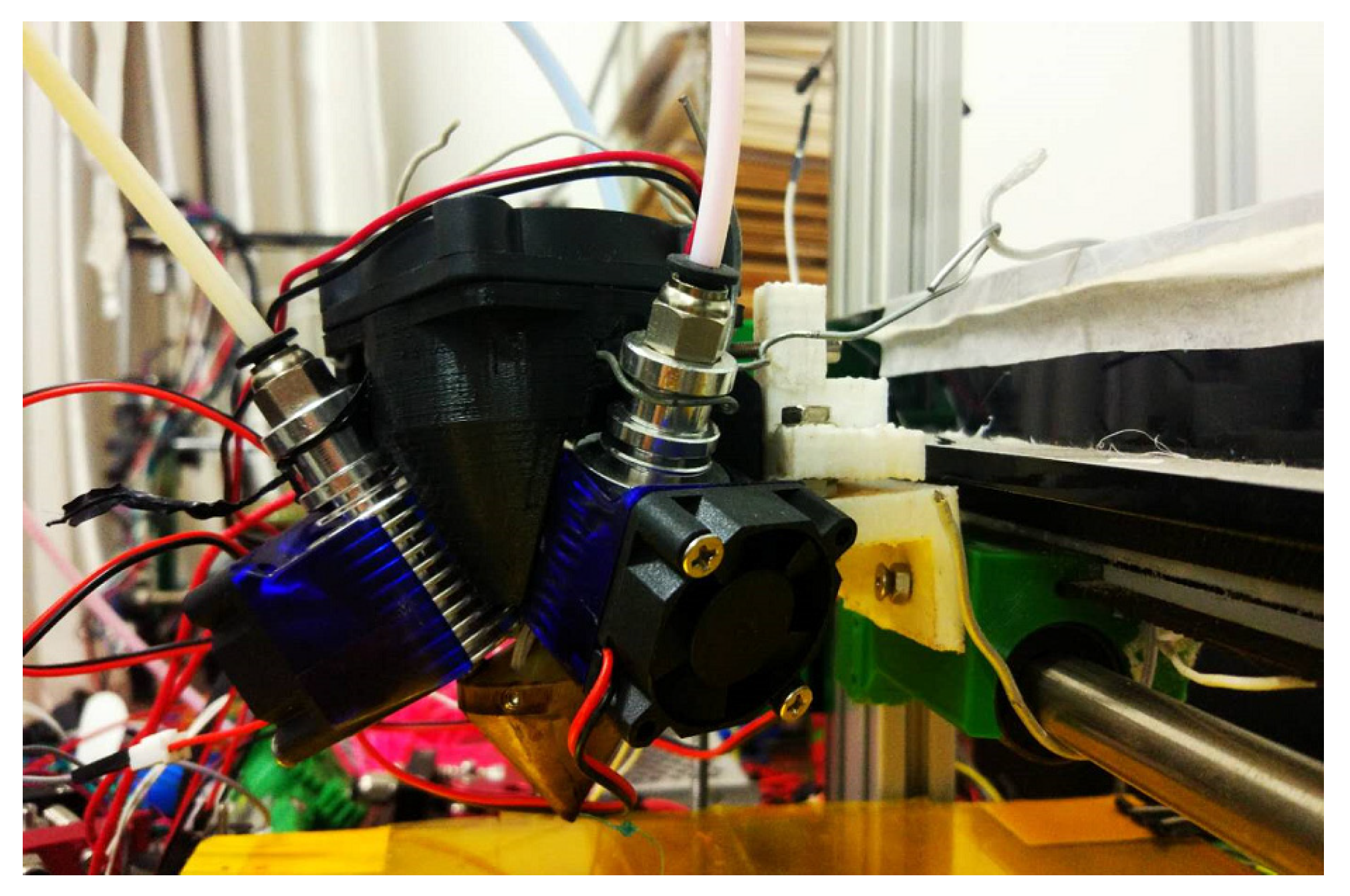
In order to simplify the calculation and eliminate the influence of some uncertain factors on the results in the research of this paper, the partial structure of the FDM color 3D printer is simplified. As can be seen from Figure 1 and Figure 2, the main beam, cross beam, and nozzle could be simplified into cantilever beam structure, and the hotbed is supported at both ends, so it could be simplified into the structure of the simply supported beam. Therefore, under suitable boundary conditions, the whole structure can be simplified and analyzed. Through the following mechanics theory analysis, we can qualitatively analyze the vibration characteristics of the FDM color 3D printer structure.
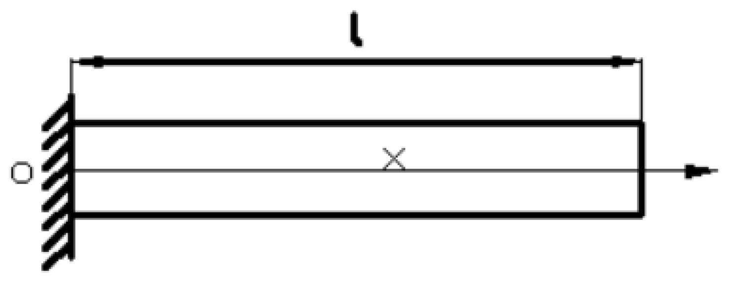
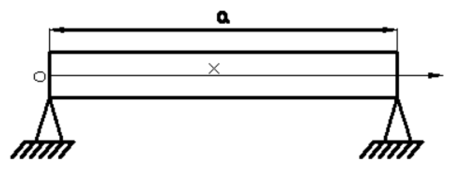
The schematic diagram of the simplified structure of the cantilever beam and simply supported beam are shown in Figure 3 and Figure 4, respectively.
Assuming that the Euler Bernoulli beam has uniform material characteristics and unified interface, the dynamic equation of the beam model is [22]
E I 4 y ( x , t ) x 4 + ρ s 2 y ( x , t ) x 2 = f ( x , t ) x m ( x , t )
where y ( x , t ) is the transverse displacement of the beam, m ( x , t ) is a moment acting on the beam, f ( x , t ) is the force acting on the beam, ρ is the mass of the unit volume beam, s is the cross-sectional area of the beam, E is Young’s modulus of the beam, I is the inertial product of the beam section to the neutral axis. The modal solution of y ( x , t ) could be written as
y ( x , t ) = i ϕ i ( x ) q i ( x ) ,   for   i = 1 , 2 ,
where ϕ i ( x ) is the I-th mode of the system and q i ( x ) is the generalized coordinate. Modal modes should be calculated by modal solutions.
ϕ i ( x ) = C 1 cos β i x + C 2 sin β i x + C 3 sinh β i x + C 4 cosh β i x
where C 1 , C 2 , C 3 , C 4 are the boundary condition constants, β i is eigenvalue. In the current study, the rod is modeled as a fixed cantilever beam, so the deflection and section angle of the fixed end of the beam are equal to zero, and the bending moment and section shear force at the free end are equal to zero. The boundary conditions of the cantilever beams could be defined as
for   x = 0 ; ϕ ( 0 ) = 0 ; ϕ ( 0 ) = 0
for   x = l ; ϕ ( l ) = 0 ; ϕ ( l ) = 0
After applying the boundary conditions (4) and (5) to the equation of the modal mode (3), (6) could be derived.
cosh β i l cosh h β i l + l = 0
where l is the length of beam. By solving β i l , the natural frequencies of each order could be defined as
ω i = ( β i l ) 2 E I ρ S l 4 ,   ( i = 1 , 2 , )
Corresponding modal functions of each order are
ϕ i ( x ) = cos β i x cosh β i x + cos β i l + cosh β i l sin β i l + sinh β i l ( sin β i x + sinh β i x ) ,   ( i = 1 , 2 , )
In the current study, the hotbed could be simplified as a simply supported beam structure. So the deflection and a section bending moment of the fixed end of the beam are equal to zero. The boundary conditions of the simply supported beam can be defined as
for   x = 0 ; ϕ ( 0 ) = 0 ; ϕ ( 0 ) = 0
for   x = a ; ϕ ( a ) = 0 ; ϕ ( a ) = 0
After applying the boundary conditions (9) and (10) to the equation of the modal mode (3), (11) could be derived as:
sin β j a = 0
where a is the length of the beam. By solving β j a , the natural frequencies of each order could be defined as
ω j = ( j π a ) 2 E I ρ S a 4 ,   ( j = 1 , 2 , )
The corresponding modal functions of each order is shown
ϕ j ( x ) = sin j π a x ,   ( j = 1 , 2 , )

2.2. Modeling and Modal Analysis of the FDM Color 3D Printer

The vibration characteristics of the frame type FDM color 3D printer are analyzed through the related mechanics theory, which shows that the analysis of the 3D printer mechanism in this paper is feasible from the vibration theory, but the 3D printer is also a practical manufacturing tool. Through complex theoretical analysis, the process can be further optimized. On the basis of the mechanical theory, FEM is selected to analyze the natural frequency and modal displacement of the model. This improves the efficiency of the vibration analysis and testing through reducing efforts on a theoretical analysis of the natural frequency and modal displacement. Ultimately the efficiency of the structural optimization of the FDM color 3D printer is improved.
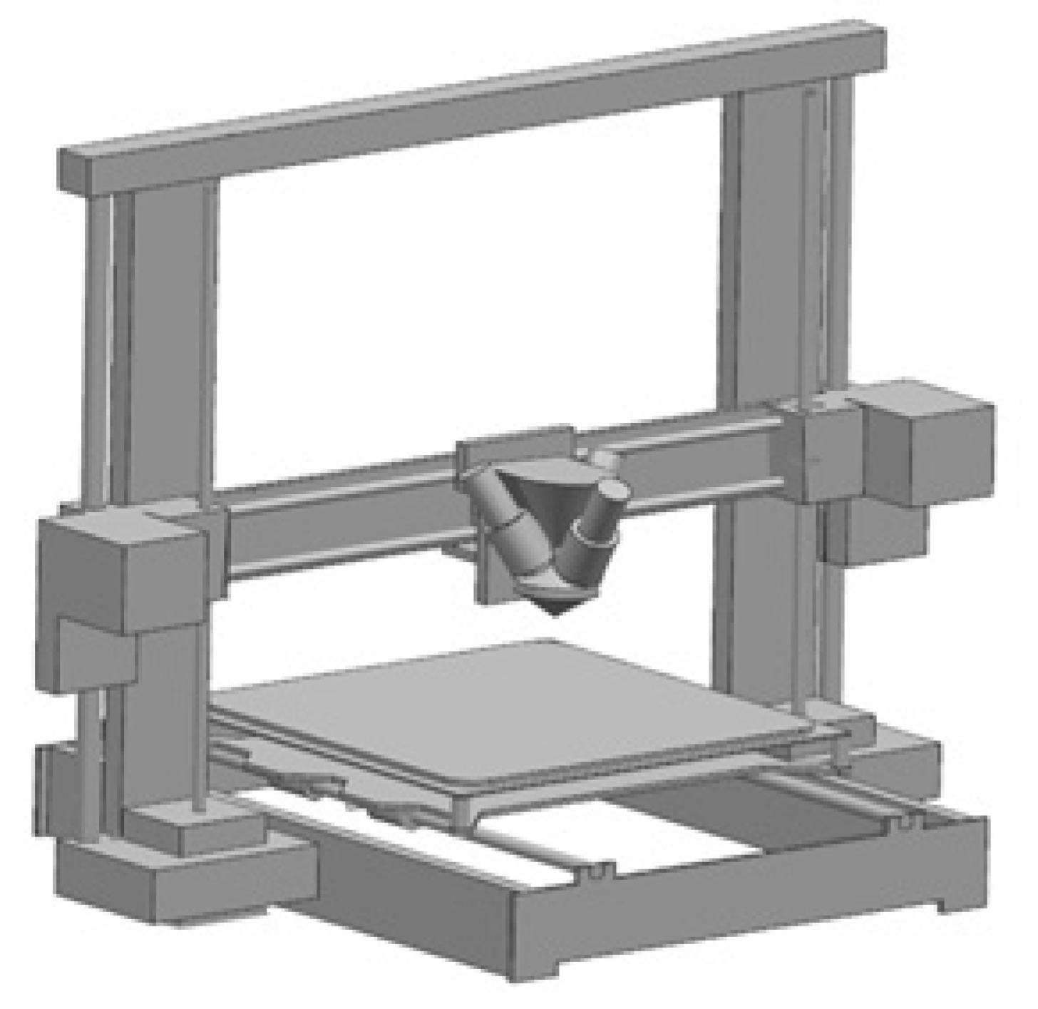
The FDM color 3D printer is mainly composed of a multi-nozzle, hotbed, cross beam, and main beam. The overall size is 360 mm × 230 mm × 350 mm. The color 3D printer model is shown in Figure 5.
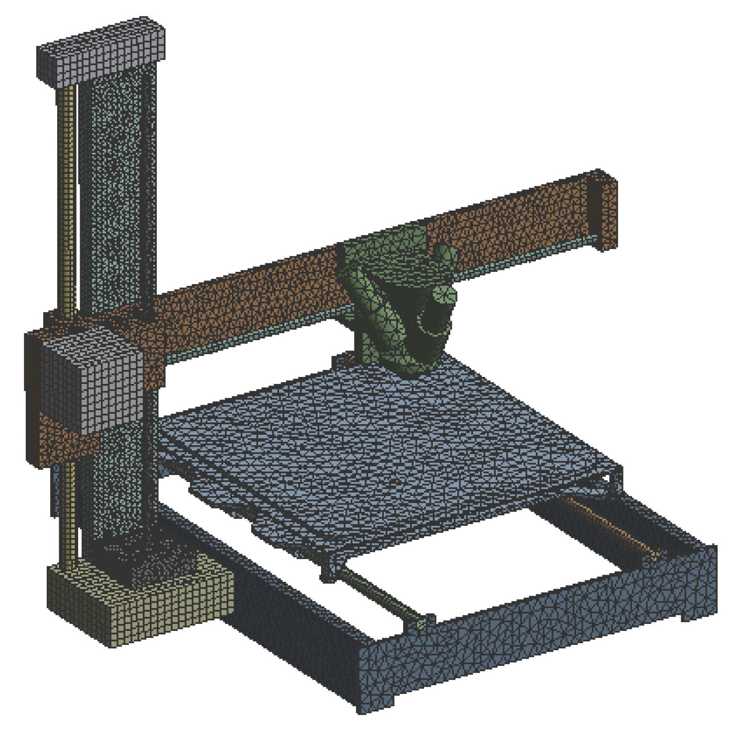
Finite element modeling directly affects the calculation results, so it is indispensable to consider such factors as model simplification, grid number, element type, the quality of the mesh, and so on. The model of the color 3D printer is simplified by considering the key factors that affect the accuracy of the simulation. In the color 3D printer model, the technical holes with a diameter of less than 10 mm are ignored, and the transition fillets are equivalent to a right angle, and the bolt holes lying in the non-key position with a diameter of less than 10 mm are ignored. The finite element model of the color 3D printer is established, as shown in Figure 6.
The hotbed, base, main beam, and the upper part of the nozzle are made of aluminum alloy, the lower part of nozzle is made of copper, the guide rails in X, Y, and Z axis are made of Q235 steel, the beam and stepper motor base are made of ABS (Acrylonitrile Butadiene Styrene). The material properties of the FDM color 3D printer are shown in Table 1.

2.3. Selection of the Accelerometer and Arrangement of the Measuring Points

The vibration response of the FDM color 3D printer is mainly measured by using MPU6050 as the acceleration sensor, and Arduino as the data collector and data processor to collect the vibration signals. The MPU6050 has a minimum measurement range of ±2 g and sensitivity of 65536LSB/4 g. In the vibration test of the FDM color 3D printer, the range is fully sufficient. The acquired acceleration data is analyzed by the methods of digital signal processing, including denoising, integral operating, FFT (Fast Fourier Fransform), etc. Then the processed data is transmitted to the upper computer.
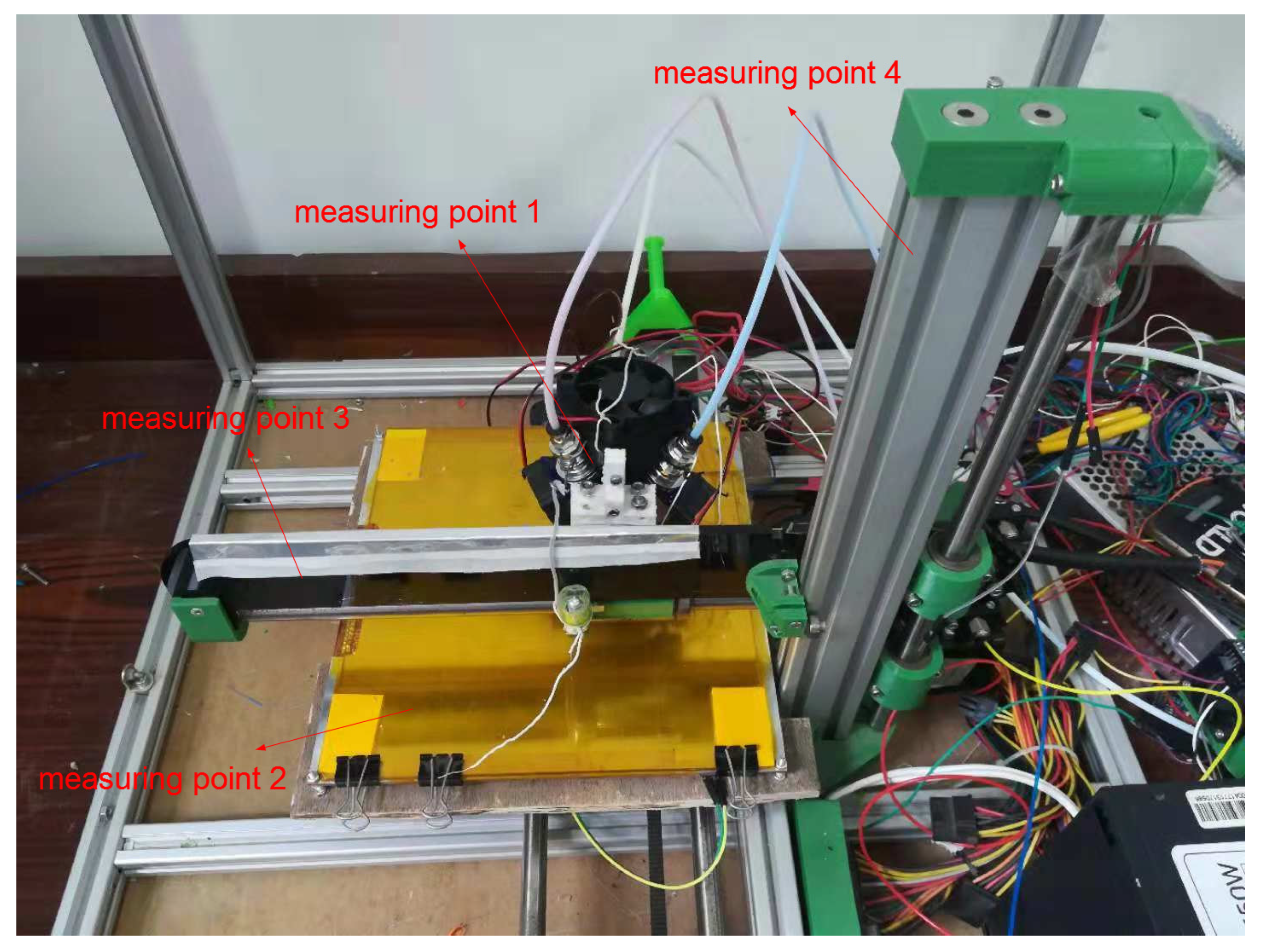
According to the results of modal analysis, four measuring points are arranged on the FDM color 3D printer, as shown in Figure 7. Measuring point 1 is placed at the position of the nozzle, measuring point 2 is placed at the position of hotbed, measuring point 3 is placed at the position of the cross beam, and measuring point 4 is placed at the position of the main beam. The vibration signals of the color 3D printer in the horizontal (X), longitudinal (Y), and vertical (Z) directions are, respectively, measured by four measuring points, thereby further analyzing the vibration signals of the 3D printer.
The parameter setting of the experiment are as follows: the 3D printer works at the printing speed of 65 mm/s, the sampling frequency of vibration test is 500 Hz, and the vibration signals of the time domain of the color 3D printer in X, Y, and Z directions are collected respectively.

2.4. The Statistical Analysis Process of the Vibration Signal of the 3D Printer

The vibration experiment was performed on the color 3D printer. The vibration signals of the color 3D printer were collected and measured by MPU6050 acceleration sensor (2012, InvenSense Inc, Sunnyvale, CA, USA) and Arduino2560 chip (2013, ALSRobotBase Company, Haerbin, China). The vibration signals were analyzed in the time domain and frequency domain by the MATLAB software (MATLAB 2014a, 2014, MathWorks, Natick, MA, USA).
Time-domain analysis refers to the acceleration information which was collected, recorded, and displayed by the acceleration sensor in the printing process. The analysis contains a large amount of information and has the characteristics of intuitive expression, easy to understand. Frequency domain analysis is one of the most commonly used signal processing methods in mechanical vibration testing. In this paper, the spectrum analysis of the color 3D printer is carried out. The purpose is to decompose the complex time waveform signal into several single harmonic components by Fourier transform to obtain the frequency structure of the signal and a series of harmonics and phase information.
By analyzing the vibration signal of the color 3D printer in the time domain and frequency domain, the effect of the geometrical and mechanical characteristics of the color 3D printer on the vibration signal was obtained. By comparing the results of the modal analysis, a solution is provided for the mechanical structure optimization of the color 3D printer.
The time-domain analysis of vibration signal can only characterize the amplitude of the signal, yet it is not enough for the study of the vibration signal. In order to further study the vibration signal of the color 3D printer, the energy distribution and frequency domain structure of the vibration signal were analyzed, and the power spectrum analysis of the obtained vibration signal were carried out.
The Fast Fourier Transform (FFT) is used to analyze the frequency spectrum of the signal. FFT is a fast algorithm of the Discrete Fourier Transform (DFT), which is obtained by improving the algorithm according to the characteristics of DFT [23]. The power spectrum analysis carried out in this paper is mainly obtained by analyzing the time domain signal processing of the acquisition by the MATLAB software.

3. Results

3.1. Modal Analysis Results of the Color 3D Printer

The excitation of the color 3D printer in the printing process is very complicated. In order to analyze the cause of the vibration, it is crucial to obtain the natural frequency of the color 3D printer by modal analysis, including the natural frequency of the color 3D printer, the modal mode, and the displacement generated by vibration. The natural frequencies and modes of the top six orders, which were obtained by FEM analysis, are shown in Table 2. The weak links and shortcomings of the structure of the color 3D printer could be found according to modal analysis.
It can be seen from Table 2 that the natural frequencies of the top six order modes of the color 3D printer are concentrated between 9 and 82 Hz, and the overall vibration of the color 3D printer is mainly bending and torsional modes.

3.2. Analysis of Vibration Characteristics of the FDM Color 3D Printer

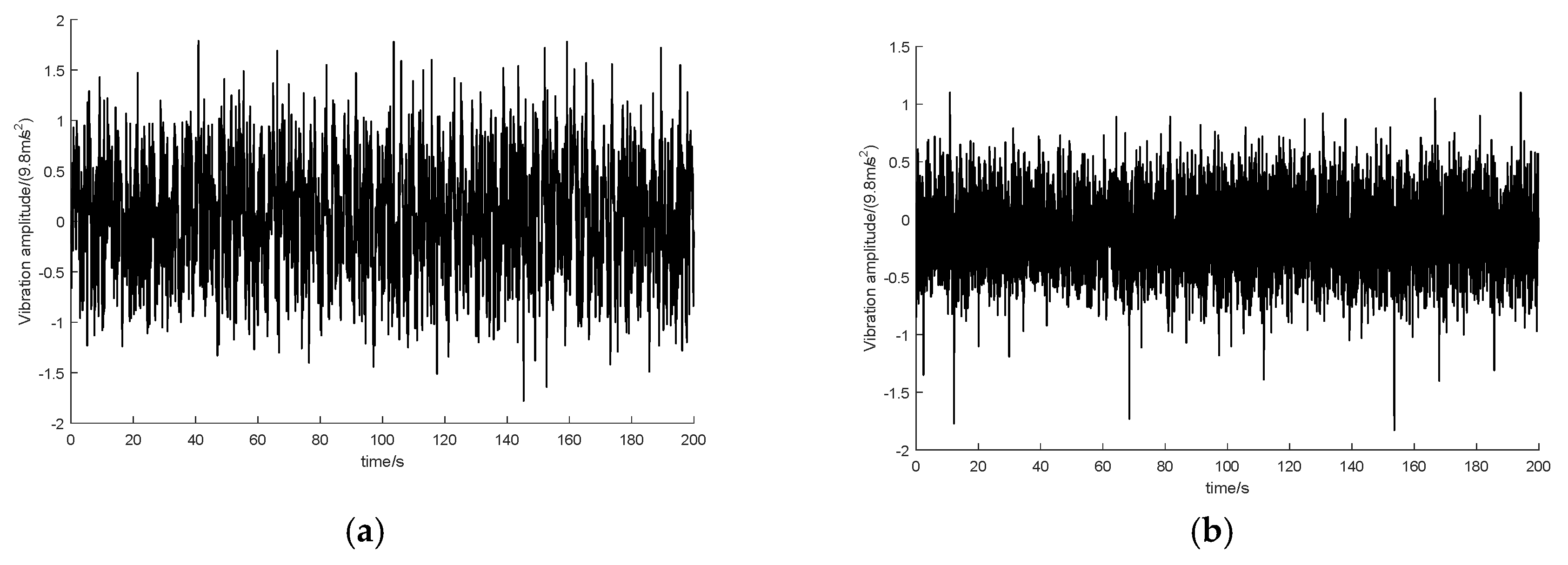
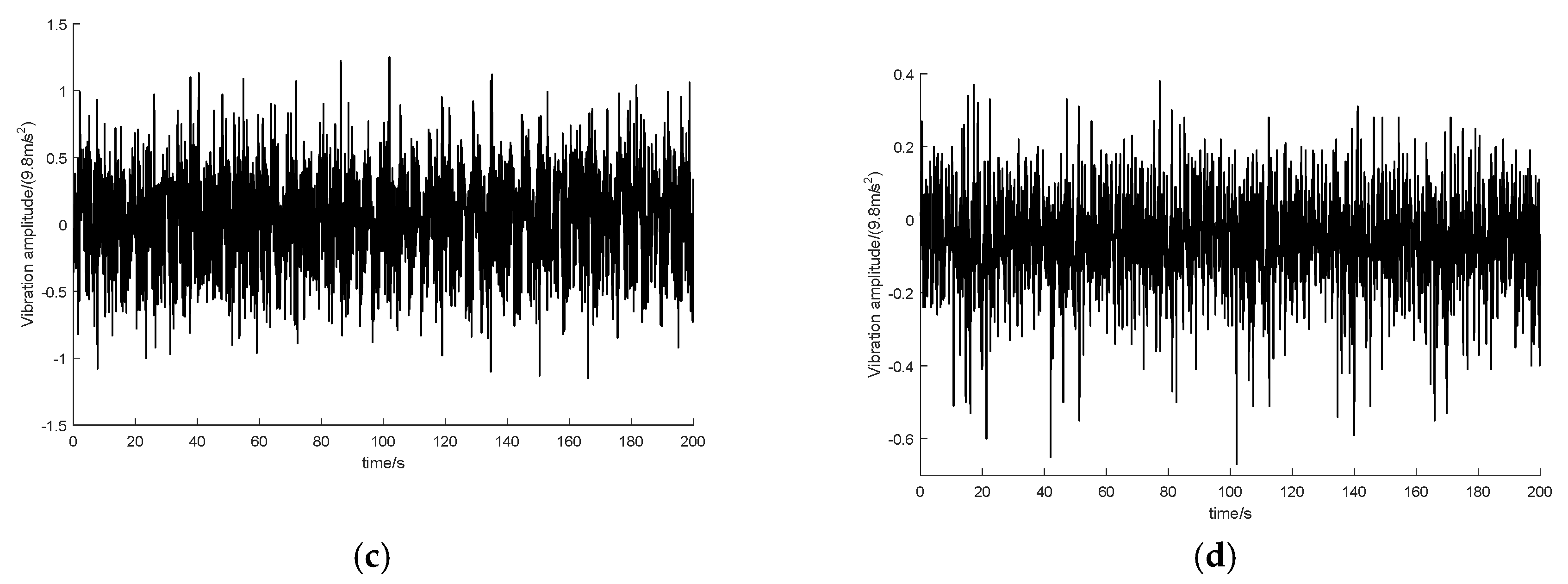
The waveforms of the time domain signal collected by the acceleration sensor are shown in Figure 8. By analyzing the results of the vibration test, it could be seen that the state of vibration of the 3D printer is relatively stable. At the same time, the vibration signals are within the measuring range of the acceleration sensor, and the vibration sensor can reflect the actual vibration characteristics more practically. In the moving parts, the effect of vibration is more obvious. Thus, there is intense vibration of the measuring points 1, 2, and 3, and there is slight vibration of the measuring point 4. Authors note that it is necessary to optimize and improve the mechanical structure because of the relatively large vibration amplitude of the measuring point 1 and measuring point 3.

3.3. Power Spectrum Analysis of the Vibration Signals

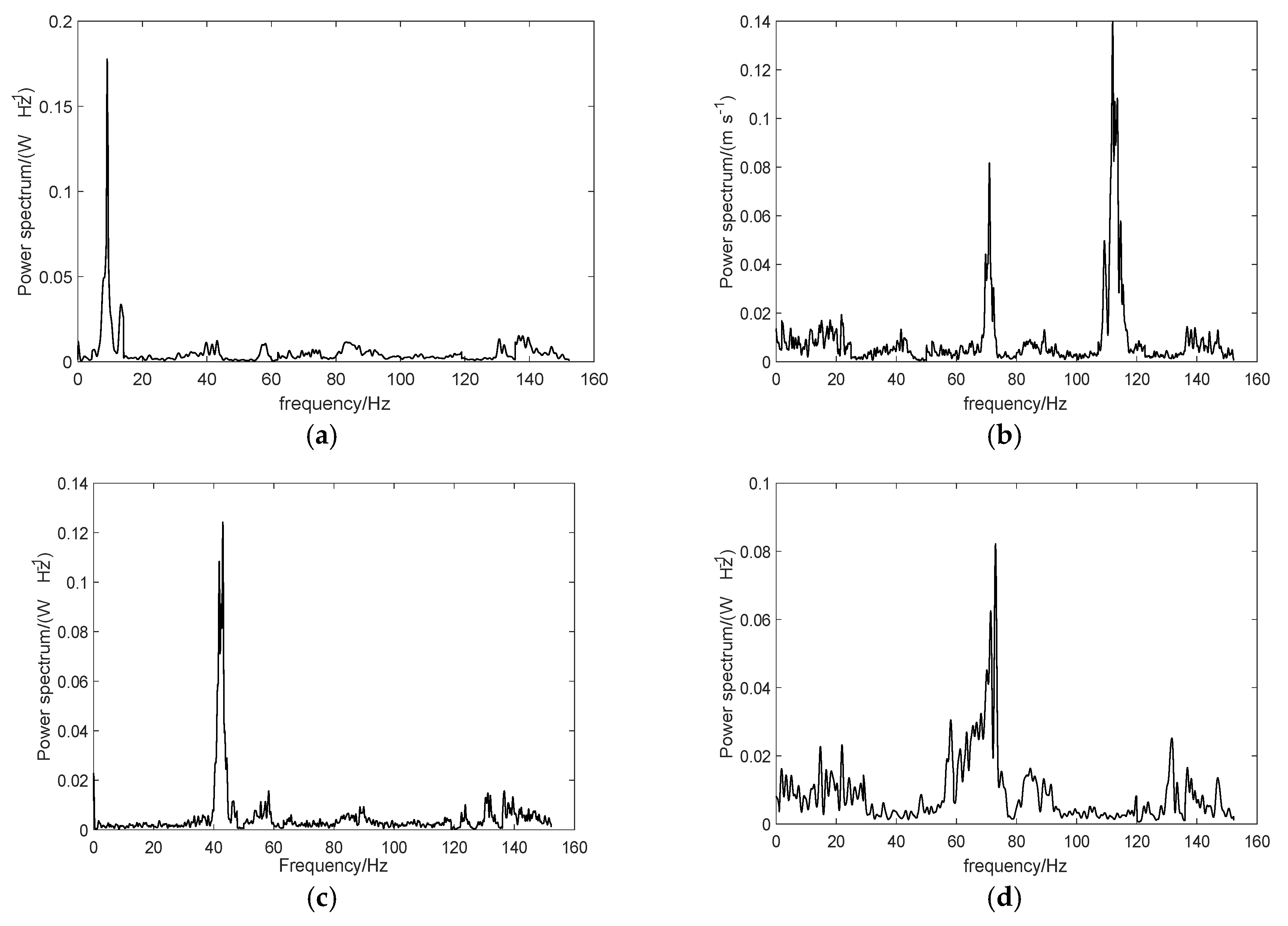
The frequency-domain analysis results of the 3D printer structure obtained by power spectrum analysis of the time domain signal are shown in Figure 9. As can be seen, the frequency of the power spectral density curve of the four measuring points is unevenly distributed, and there are one or two peak values of the power spectrum, which indicates the actual vibration main frequency of the measuring point. Through the power spectrum analysis, the vibration characteristics of the 3D printer in the actual working state can be tested and compared with the theoretical values to obtain the resonance characteristics of the 3D printer.
The vibration signal curve of frequency domain demonstrates that the main vibration frequency of measuring point 1 is next to 9 Hz, that of measuring point 2 is next to 71 Hz and 112 Hz, that of measuring point 3 is next to 43 Hz, and that of measuring point 4 is next to 73 Hz. The results of the analysis are compared with the experimental record, and the resonance of the color 3D printer could occur if the vibration frequency of the color 3D printer components coincides with the natural frequency. The vibration frequency obtained from the measuring point 1 at the position of nozzle is close to its natural frequency of 9.985 Hz, which will lead to the resonance of the color 3D printer nozzle in the bending direction. The vibration frequency obtained from the measuring point 3 at the position of the cross beam is close to its natural frequency of 43.094 Hz, which will lead to the resonance of the color 3D printer beam in the bending direction. According to the analysis results, the components of the color 3D printer are improved to avoid resonance and improve the printing accuracy of the color 3D printer.

3.4. Optimization of the FDM Color 3D Printer

The overall vibration characteristics of the original 3D printer were improved by changing the mechanical structure. From the vibration pattern, it can be seen that the beam and nozzle are the main parts of the vibration of the 3D printer. According to the actual working conditions combined with the time domain and frequency domain analysis, the edge of cross beam and the connecting part of the nozzle are the weakest parts, which will lead to large deformation. Based on the analysis of the mechanical structure of the FDM color 3D printer, the following improvements are made: one end of the cantilever beam is fixed to form a gantry structure, and the single-rail of the main beam is made into a vertical double-rail structure, and the improved FDM color 3D printer is shown in Figure 10.
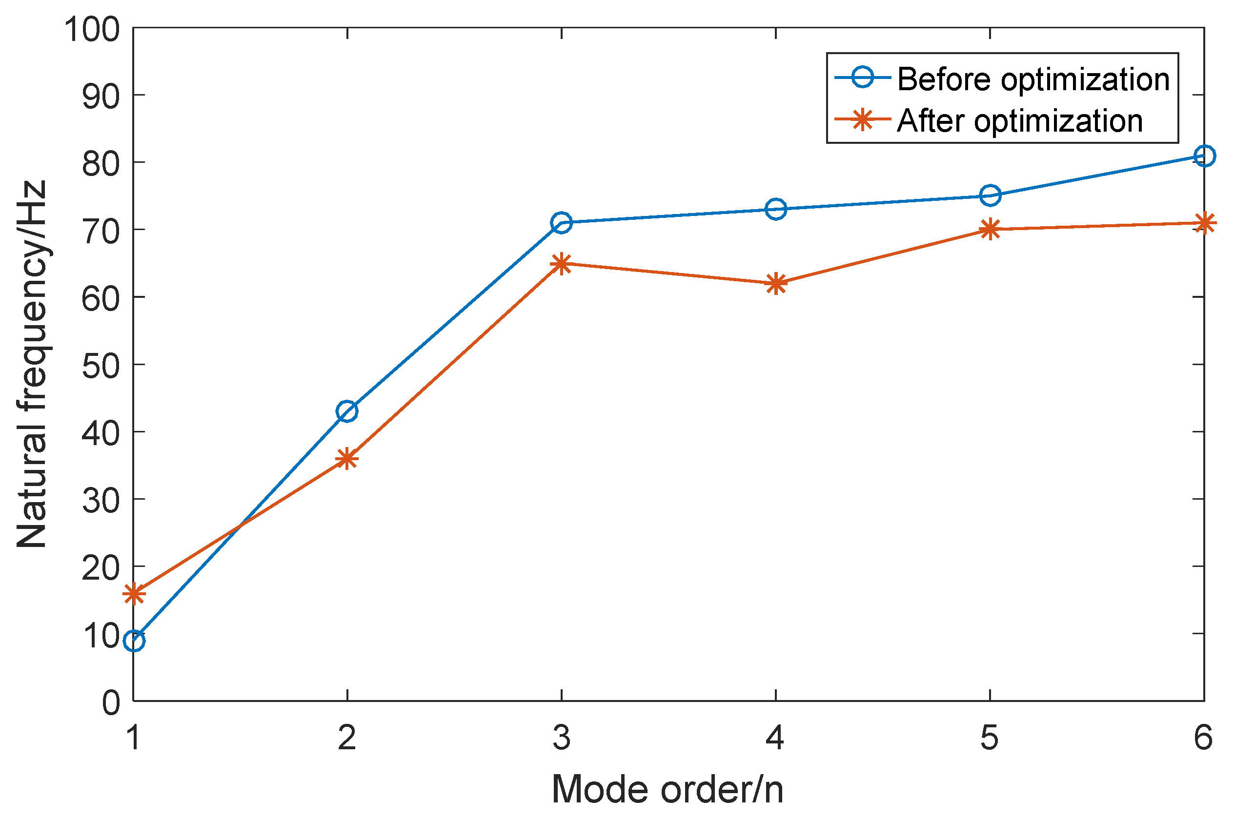
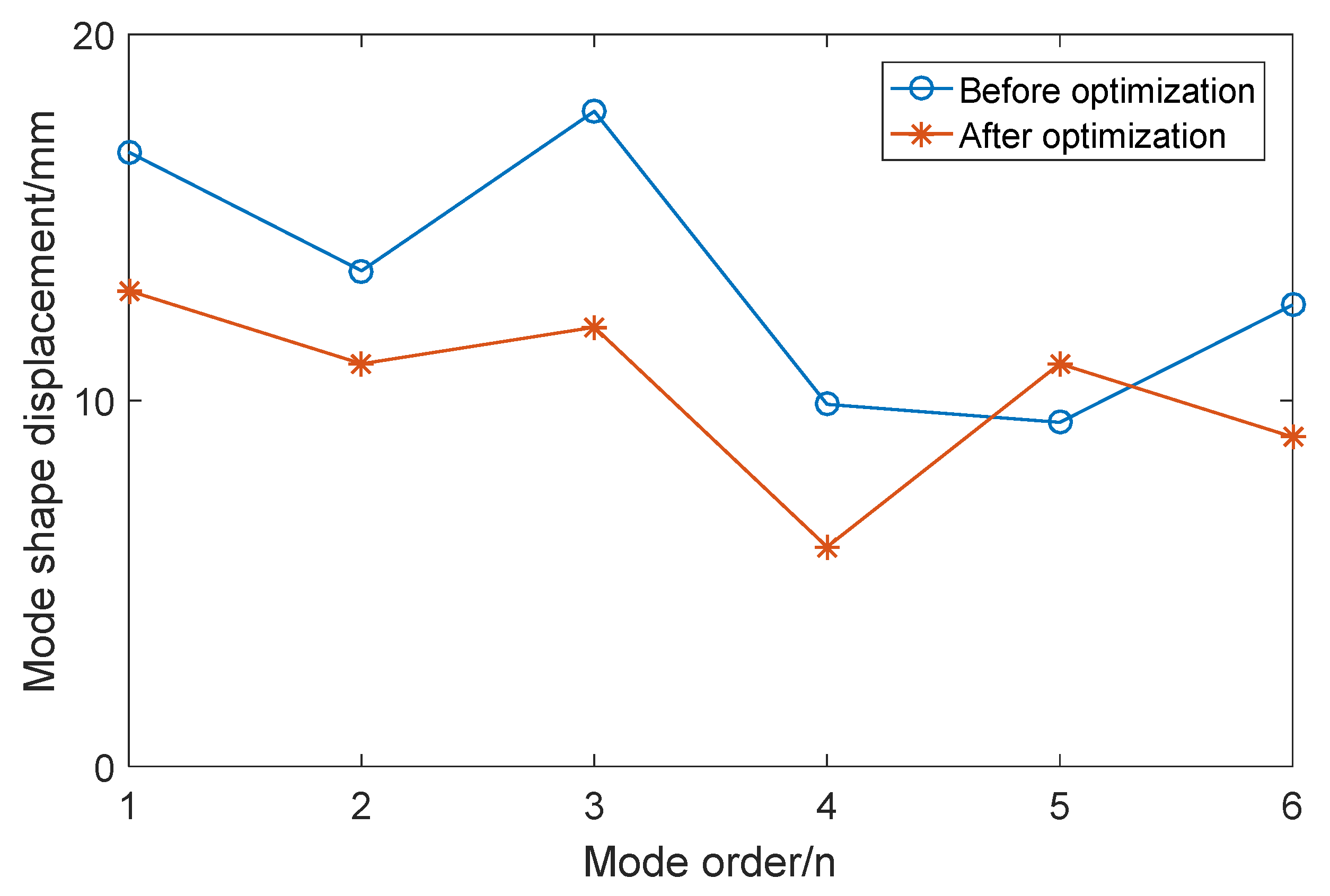
FEM analysis is carried out after obtaining the new FDM color 3D printer structure. The relationship between the modal order and the corresponding natural frequency before and after optimization is shown in Figure 11. The natural frequency of the first-order bending of the nozzle is improved, and the natural frequency of the first-order bending of cross beam is reduced, which can effectively improve the structure resonance of the color 3D printer. The optimized mechanical structure has a lower natural frequencies except for the first-order mode, and the natural frequencies of other orders are degraded. The information of vibration modal shape displacement of the structure of the FDM color 3D printer is obtained simultaneously by FEM analysis. The relationship between the modal order and the corresponding modal shape displacement before and after optimization is shown in Figure 12.
The optimized mechanical structure has a lower displacement of the mode shape except for the fifth-order mode, and the modal displacement of other orders is significantly decreased. Therefore, the overall vibration is effectively reduced and the optimization scheme obtained by the analysis process has a significant effect on the optimization of the vibration characteristics.
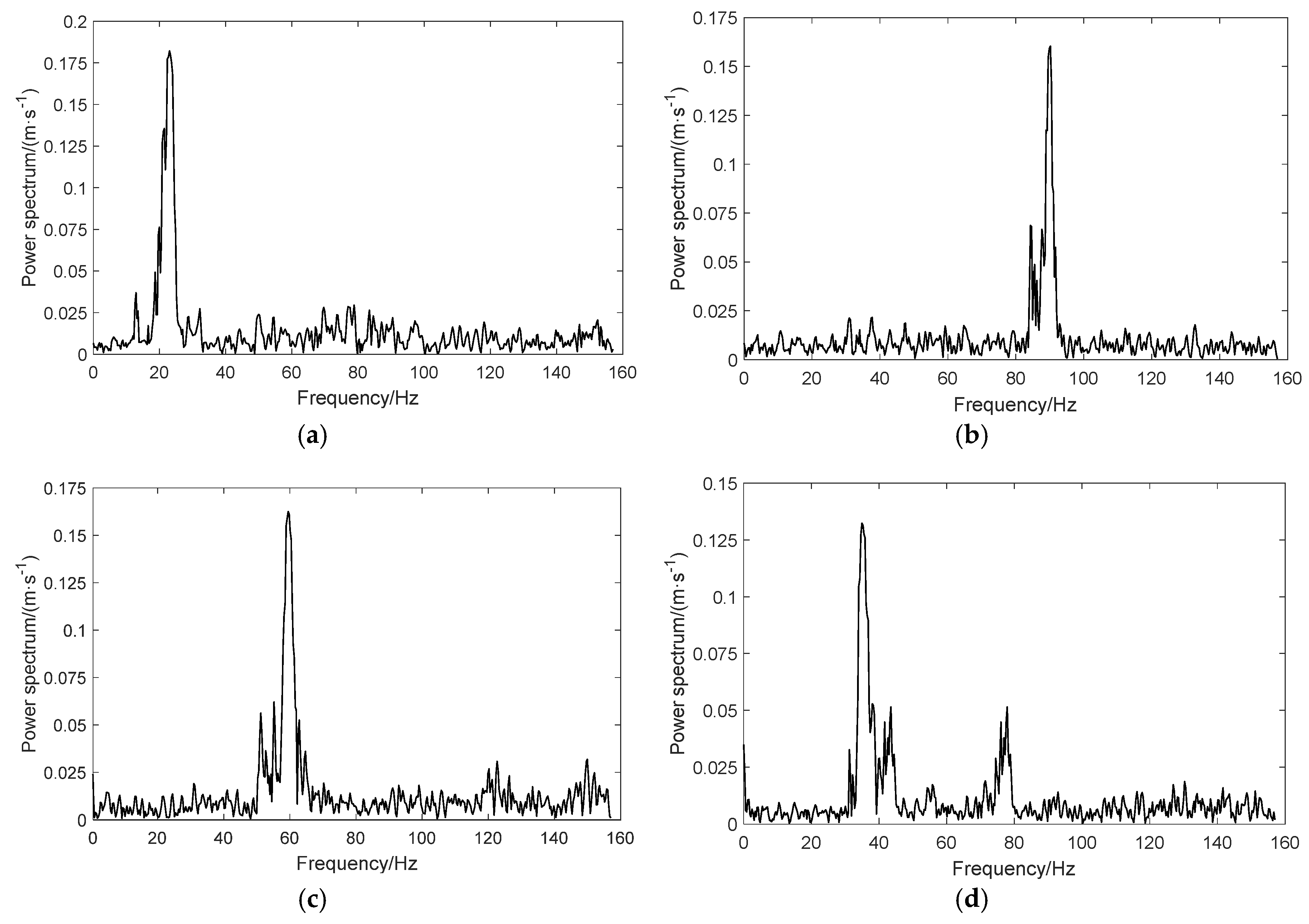
The difference in the frequency spectrum before and after optimization is shown in Figure 13. In the figure, the position of the peak changes to some extent. The most obvious is that the peak position of the main beam and the cross beam changes. The main reason is that there are substantial changes in the structure of these two parts. A great change in the peak position of the frequency spectrum indicates that the changes in the structure have an effect on the actual vibration frequency. The main vibration frequency of each part of the improved mechanism is not the same as the actual natural frequency. As a result, the optimized mechanism could effectively avoid resonance.
According to the optimization scheme, the FDM color 3D printer is improved and tested taking a cylinder as the test model and dividing color regions leveraging the slicing software to obtain the decomposition effects of different colors. The printed objects before and after the mechanical structure optimization are shown in Figure 14a,b accordingly. As it is shown in Figure 14a, the printed object before optimization has an obvious tilt angle of about 70° with poor surface roughness. The printed object after optimization has better verticality and surface roughness. As it is shown in Figure 14b, the echeloned of the printed object before the optimization is more obvious and there is an obvious missed print between the layers. The printed object after optimization has been significantly improved in both echeloned and forming accuracy. The color boundary is more distinct, and the rationality of optimizing and improving the design of the color 3D printer is verified.
In the process of printing, the extrusion filament material is sufficient from beginning to end. The different vibration types will produce different missed printing effects. Missed printing can be divided into two categories: internal missed printing and external missed printing, as can be shown in Figure 15. When the random vibration is outward, the extrusion filament material will adhere to the surface of the cylinder because of the radian of the cylinder, then the effect of external missed printing will be forming. When the random vibration is inward, the extrusion filament material will disappear because the printing arc is overlapped the internal part, then the obvious hollowing will be forming an internal missed printing.
The size errors of the model before and after optimization in the actual printing case with a printing speed of 65 mm/s are shown in Table 3. The size errors in the three directions of X, Y, and Z are significantly reduced. Therefore, the optimization scheme could improve the actual printing accuracy and is suitable for optimizing the accuracy problem based on vibration characteristics.
The improvement of the size error in Y direction of the color 3D printer is the most significant, mainly because the vibration characteristics of cross beam are effectively optimized. The gantry structure and vertical double guide rail structure used in color 3D printer have a good improvement effect on improving the vibration characteristics.

4. Discussion

The purpose of this study is to optimize the vibration characteristics of existing color 3D printers. In order to achieve this, the whole mechanism of color 3D printer can be simplified into the cantilever beam and the simply supported beam for analysis. The feasibility of analyzing and optimizing the structure of the FDM color 3D printer by using vibration testing method is qualitatively analyzed in theory.
There are several findings from the theoretical and experimental results. Firstly, the general vibration trend towards each component of the 3D printer could be obtained through the time domain analysis of the vibration signal. Secondly, through frequency domain analysis of the vibration signal, the color mixing nozzle and the beam have resonated compared with the theoretical analysis results. Thirdly, the mode shape displacement, time-domain analysis results, and frequency domain analysis results are the basis of the improved mechanical structure and proposal of the gantry structure, and double rail structure. Besides, the printing error has been reduced, and the overall vibration characteristics have been improved due to lower natural frequency and reduced modal displacement. Hence, the proposed vibration characteristic analysis process is suitable for optimizing the design and improving the mechanical structure of the color 3D printer.
An online quality monitoring in additive manufacturing processes was proposed in previous studies [24] utilizing accelerometers, thermocouples, video borescope, and an infrared temperature sensor. After several sets of experiments, an empirical relationship between input parameters (feed/flow ratio, layer height, and extruder temperature) and surface roughness was found. Compared to MEMS accelerometer, low-cost accelerometers are used to analyze the vibration characteristics of the nozzle. But only the current nozzle was predicted and analyzed. There was no further optimization design for the performance of the nozzle. In previous studies regarding vibration based on AM condition monitoring, there are more optimization options to improve the results. While in this paper, both the testing and optimization of the vibration sensor are elaborated.
There are some limitations in the current study. The acquisition of the results of the frequency domain analysis could be obtained by secondary processing of the time domain signal, and it led to the lack of real-time of the data processing. Only the optimization of the mechanical structure was carried out in this paper.
Future research may include through the proposed vibration characteristic analysis process, the parameters of FDM color 3D printer can be optimized and analyzed.

5. Conclusions

In this paper, the structure of the FDM color 3D printer is qualitatively analyzed. Firstly, the whole structure of the FDM color 3D printer is simplified and theoretically analyzed by the cantilever beam and simply supported beam, and the natural frequency and mode shape displacement of the whole device are obtained through FEM analysis. Then the vibration test based on MPU6050 acceleration sensor is applied, and the power spectrum of the color 3D printer under the actual working condition is obtained with the higher speed and lower cost. Finally, the vibration characteristics optimizing method is used to improve the mechanical structure of color 3D printer. Combined with the results of FEM analysis and vibration test, the result after optimization shows the forming accuracy has significantly improved, the size error in X direction reduces by 28.57%, the size error in Y direction reduces by 78.26%, and the size error in Z direction reduces by 62.5%, and the cumulative error angle due to the printing echeloned phenomenon is corrected from 70° to 90°. The modal optimizing data indicates that the natural frequency has been changed and the mode shape displacement has been declined.

Author Contributions

D.Z. and S.H. conceived the original idea and wrote the paper; Z.L. designed and conducted experiments, S.Q. analyzed the experimental data; S.H. provided supervision and funding acquisition.

Funding

This research was funded by the Natural Science Foundation of Shandong Province (Grant no. ZR201709210313), the Project of Shandong Province Higher Educational Science and Technology Program (Grant no. J17KA018) and the Science & Technology Innovation Fund for Graduate Students of Shandong University of Science and Technology (Grant no. SDKDYC190112).

Conflicts of Interest

The authors declare no conflict of interest.

References

  1. Turner, B.N.; Strong, R.; Gold, S.A. A review of melt extrusion additive manufacturing processes: I. Process design and modeling. Rapid Prototyp. J. 2014, 20, 192–204. [Google Scholar] [CrossRef]
  2. Balletti, C.; Ballarin, M.; Guerra, F. 3D printing: State of the art and future perspectives. J. Cult. Herit. 2017, 26, 172–182. [Google Scholar] [CrossRef]
  3. Shih, C.C.; Burnette, M.; Staack, D.; Wang, J.; Tai, B.L. Effects of cold plasma treatment on interlayer bonding strength in FFF process. Addit. Manuf. 2019, 25, 104–111. [Google Scholar] [CrossRef]
  4. Kim, M.K.; Lee, I.H.; Kim, H.-C. Effect of fabrication parameters on surface roughness of FDM parts. Int. J. Precis. Eng. Manuf. 2018, 19, 137–142. [Google Scholar] [CrossRef]
  5. Han, S.; Xiao, Y.; Qi, T.; Li, Z.; Zeng, Q. Design and analysis of fused deposition modeling 3D printer nozzle for color mixing. Adv. Mater. Sci. Eng. 2017, 2017, 2095137. [Google Scholar] [CrossRef]
  6. Kim, H.; Park, E.; Kim, S.; Park, B.; Kim, N.; Lee, S. Experimental study on mechanical properties of single- and dual-material 3D printed products. In Proceedings of the 45th SME North American Manufacturing Research Conference, Los Angeles, CA, USA, 4–8 June 2017; pp. 887–897. [Google Scholar]
  7. Reiner, T.; Carr, N.; Mech, R.; St’ava, O.; Dachsbacher, C.; Miller, G. Dual-color mixing for fused deposition modeling printers. Comput. Graph. Forum 2014, 33, 479–486. [Google Scholar] [CrossRef]
  8. Soares, J.B.; Finamor, J.; Silva, F.P.; Roldo, L.; Candido, L.H. Analysis of the influence of polylactic acid (PLA) colour on FDM 3D printing temperature and part finishing. Rapid Prototyp. J. 2018, 24, 1305–1316. [Google Scholar] [CrossRef]
  9. Porter, D.A.; Hoang, T.V.T.; Berfield, T.A. Effects of in-situ poling and process parameters on fused filament fabrication printed PVDF sheet mechanical and electrical properties. Addit. Manuf. 2017, 13, 81–92. [Google Scholar] [CrossRef] [Green Version]
  10. Balani, S.B.; Chabert, F.; Nassiet, V.; Cantarel, A. Influence of printing parameters on the stability of deposited beads in fused filament fabrication of poly(lactic) acid. Addit. Manuf. 2019, 25, 112–121. [Google Scholar] [CrossRef]
  11. Ali, M.H.; Mir-Nasiri, N.; Ko, W.L. Multi-nozzle extrusion system for 3D printer and its control mechanism. Int. J. Adv. Manuf. Technol. 2016, 86, 999–1010. [Google Scholar] [CrossRef]
  12. Brunton, A.; Arikan, C.A.; Urban, P. Pushing the limits of 3D color printing: Error diffusion with translucent materials. ACM Trans. Graph. 2015, 35, 4. [Google Scholar] [CrossRef]
  13. Tlegenov, Y.; Wong, Y.S.; Hong, G.S. A dynamic model for nozzle clog monitoring in fused deposition modelling. Rapid Prototyp. J. 2017, 23, 391–400. [Google Scholar] [CrossRef]
  14. Minetola, P.; Galati, M. A challenge for enhancing the dimensional accuracy of a low-cost 3D printer by means of self-replicated parts. Addit. Manuf. 2018, 22, 256–264. [Google Scholar] [CrossRef]
  15. Xu, Z.M.; Wang, H.B.; Yang, G. Research on the influence of geometrical parameters on the contour precision of 3D printing parts. Mach. Des. Manuf. 2017, 5, 113–115. [Google Scholar]
  16. Han, S.L.; Qi, T.; Li, Z.Y.; Xu, H.G. Precision analysis and experimental investigations of fused deposition molding technology. Mach. Tool Hydraul. 2017, 45, 90–94. [Google Scholar]
  17. Armillotta, A.; Bellotti, M.; Cavallaro, M. Warpage of FDM parts: Experimental tests and analytic model. Robot. Comput. Integr. Manuf. 2018, 50, 140–152. [Google Scholar] [CrossRef]
  18. Mohamed, O.A.; Masood, S.H.; Bhowmik, J.L. Optimization of fused deposition modeling process parameters for dimensional accuracy using I-optimality criterion. Measurement 2016, 81, 174–196. [Google Scholar] [CrossRef]
  19. Bi, C.F. The kinematic analysis and simulation of 3D print parallel robot mechanism based on RecurDyn. Mach. Des. Manuf. 2016, 3, 243–246. [Google Scholar]
  20. Tlegenov, Y.; Hong, G.S.; Lu, W.F. Nozzle condition monitoring in 3D printing. Robot. Comput. Integr. Manuf. 2018, 54, 45–55. [Google Scholar] [CrossRef]
  21. Azmi, M.S.; Ismail, R.; Hasan, R.; Alkahari, M.R.; Tokoroyama, T. Vibration analysis of FDM printed lattice structure bar. In Proceedings of the SAKURA Symposium on Mechanical Science and Engineering, Nagoya, Japan, 12 September 2017; pp. 33–35. [Google Scholar]
  22. Bagheri, S.; Nikkar, A.; Ghaffarzadeh, H. Study of nonlinear vibration of Euler-Bernoulli beams by using analytical approximate techniques. Lat. Am. J. Solids Struct. 2014, 11, 157–168. [Google Scholar] [CrossRef] [Green Version]
  23. Pandotra, H.; Malhotra, E.; Rajwade, A.; Gurumoorthy, K.S. Signal recovery in perturbed fourier compressed sensing. In Proceedings of the 2018 IEEE Global Conference on Signal and Information Processing, Anaheim, CA, USA, 26–28 November 2018; pp. 326–330. [Google Scholar]
  24. Rao, P.K.; Liu, J.; Roberson, D.; Kong, Z.; Williams, C. Online real-time quality monitoring in additive manufacturing processes using heterogeneous sensors. J. Manuf. Sci. Eng. Trans. ASME 2015, 137, 061007. [Google Scholar] [CrossRef]
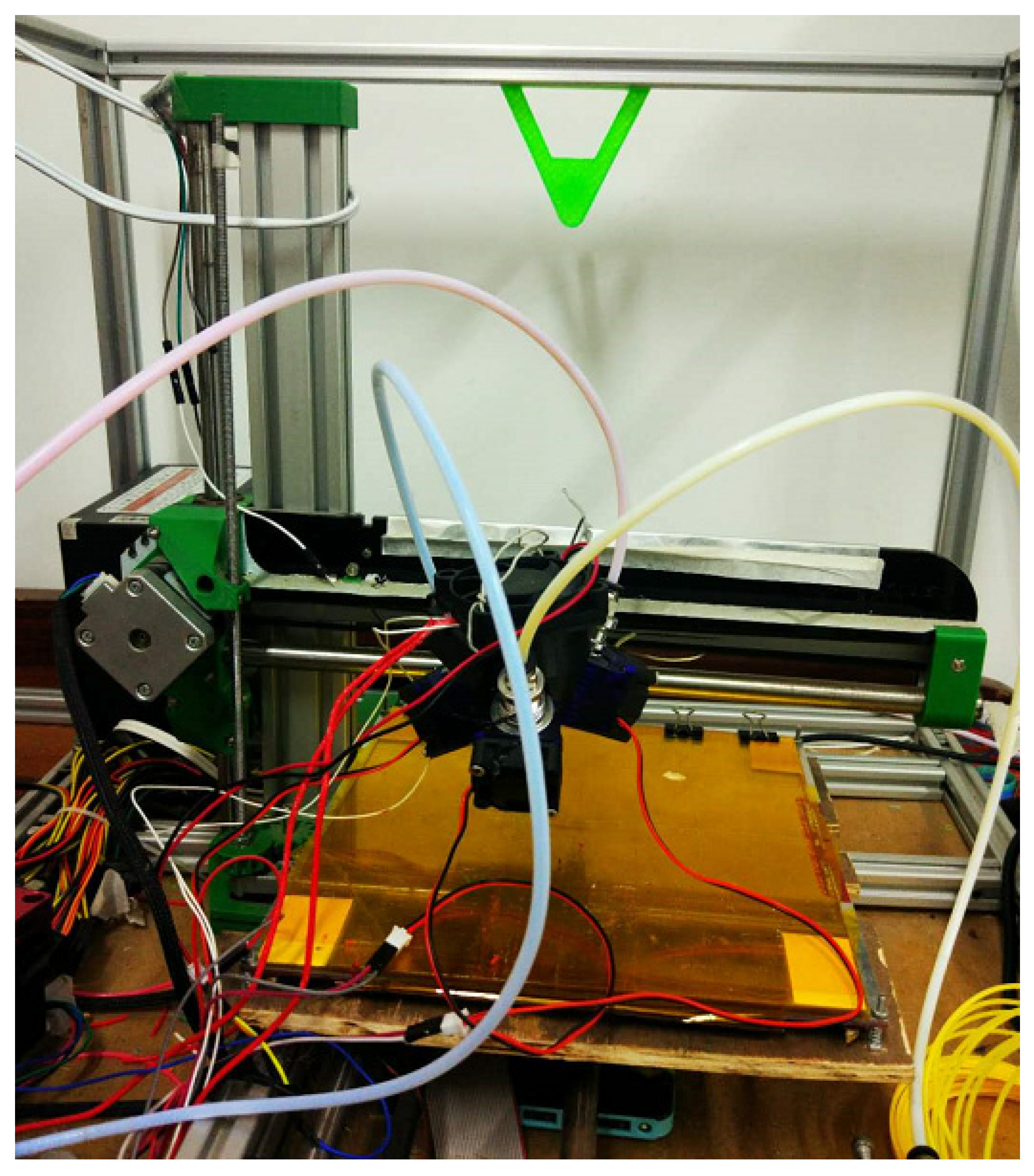
Figure 1. The whole structure of the color 3D printer.
Applsci 09 04154 g001
Figure 2. The structure of color 3D printer nozzle.
Applsci 09 04154 g002
Figure 3. Schematic diagram of the simplified structure of the cantilever beam.
Applsci 09 04154 g003
Figure 4. Schematic diagram of the simplified structure of the simply supported beam.
Applsci 09 04154 g004
Figure 5. The color 3D printer model.
Applsci 09 04154 g005
Figure 6. The finite element model of the color 3D printer.
Applsci 09 04154 g006
Figure 7. Vibration measuring points arrangement.
Applsci 09 04154 g007
Figure 8. Vibration signals of four measuring points. (a) measuring point 1, (b) measuring point 2, (c) measuring point 3, and (d) measuring point 4.
Applsci 09 04154 g008aApplsci 09 04154 g008b
Figure 9. Frequency spectrum of four measuring points before optimization. (a) measuring point 1, (b) measuring point 2, (c) measuring point 3, and (d) measuring point 4.
Applsci 09 04154 g009
Figure 10. The improved color 3D printer.
Applsci 09 04154 g010
Figure 11. Comparison of natural frequencies results before and after optimization.
Applsci 09 04154 g011
Figure 12. Comparison of mode shape displacement results before and after optimization.
Applsci 09 04154 g012
Figure 13. The frequency spectrum of four measuring points after optimization. (a) measuring point 1, (b) measuring point 2, (c) measuring point 3, and (d) measuring point 4.
Applsci 09 04154 g013
Figure 14. Comparison of printing accuracy before and after optimization: (a) results of model 1; (b) results of model 2.
Applsci 09 04154 g014
Figure 15. Internal missed printing and external missed printing.
Applsci 09 04154 g015
Table 1. Material properties of the FDM color 3D printer.
MaterialElastic Modulus (GPa)Poisson’s RatioDensity (kg·m−3)
ABS30.3941050
Aluminum alloy710.332770
Q2352070.297850
Copper1190.3268900
Table 2. Description of natural frequencies and modes of the top six order.
OrderNatural Frequency (Hz)Main Mode
19.985Nozzle bending along the x-axis
243.094Crossbeam bending along the y-axis
372.212Nozzle torsion along the z-axis
472.29Hotbed bending along the y-axis
575.071Hotbed torsion along the x-axis
681.745Main beam torsion along the y-axis
Table 3. The size error of the model before and after optimization.
Size Error (mm)
X-DirectionY-DirectionZ-Direction
Before optimization0.211.380.08
After optimization0.150.30.03