1. Introduction
High-cycle fatigue (HCF) failure of the turbine blades of aero-engines caused by high vibrational stresses is one of the main causes of aero-engine incidents. Due to its insensitivity to temperature and its simple structure, the under-platform damper was widely used to reduce the vibration of the aero-engine turbine blades [
1]. To predict the response of the turbine blade with an under-platform damper more and more accurately, recently, there have been quite a lot of developments in the calculations and analyses of under-platform dry friction damper. These studies are mainly about structural dynamic model, dry friction contact model, and methods for solving response of the nonlinear system.
Menq [
2] and Sanliturk [
3] studied the friction contact and the effect on the vibration reduction of the two-dimensional friction motion. Xia [
4] proposed a model for investigating the stick-slip motion caused by dry friction of a two-dimensional oscillator under arbitrary excitations and provided a numerical approach to investigate the system with the Coulomb friction law. Shan and Zhu [
5,
6] used the numerical tracking method to analyze the complex motion and studied the dynamic response of the plate blade with an under-platform damper. Ma et al. established a dynamic model of rotating shrouded blades considering the effects of the centrifugal stiffening and spin softening of the blade [
7]. He B and Ouyang H studied the forced vibration response of a turbine blade with a new kind of under-platform damper, in which the vertical motion of the damper leads to time-varying contact forces and can cause horizontal stick-slip motion [
8]. For understanding the actual dynamics of the blade–damper interaction, a novel experimental test rig was developed to extensively investigate the damper’s dynamic behavior [
9,
10]. Umer and Botto [
11] explored the contact forces and relative displacement between the damper–blade contact interface with an experimental study for the first time. Liao and Li [
12] proposed a two-dimensional friction ball/plate model and established a dynamics model of the rotor with elastic support/dry friction dampers.
Qi and Gao [
13,
14] established a one-dimensional macro-micro slip friction model to analyze the dynamic characteristics of the damper system, and compared it with the results of the finite element method. The phenomenological macro-slip of dry friction modeling was described in mathematical form by two approaches, and both approaches were illustrated using different acceleration excitations to describe the differences between them [
15]. A model was proposed to characterize friction contact of non-spherical contact geometries obeying the Coulomb friction law with constant friction coefficient and constant normal load and the dissipated energies were obtained for different contact geometries [
16]. A decrease in vibrational amplitudes was explained by changes in boundary conditions induced by a stick/slip behavior, and the contribution of respective energy dissipation and change of contact state on peak levels was shown [
17]. He and Ren [
18] studied the reducing vibrational characteristics of the blade by the two-dimensional friction model and finite element model. A purposely developed contact model was tuned on a single-contact test and then included in the numerical model of a curved-flat damper to simulate its cylindrical interface [
19]. A microslip model was developed for analyzing the damping effect of under-platform dampers for turbine blades, but the inertia and rotating effects of the damper were ignored for simplicity [
20].
Wang and Zhang [
21] studied the free vibration and forced vibration of a dry friction oscillator, which was composed of the Iwan model and a mass by harmonic balance method. The multi-harmonic balance method was used to analyze the periodic vibrations of the damper system and to investigate the steady-state solutions of the nonlinear system [
22]. A method to predict the nonlinear steady-state response of a complex structure was described, and two differential forms of friction force were given to solve the tangential force of the blades with under-platform dampers accurately [
23]. The vertical contact forces and the resultant friction forces acted as moving loads, and the finite element method and the modal superposition method were used to obtain the numerical modes and to solve the dynamic response of the dry friction dampers [
24]. Yu and Xu studied the properties of cubic nonlinear systems with dry friction damping and an approximate method was used to get the frequency-response function [
25].
In the most studies, it is generally assumed that the bladed disc is stationary, to simplify the dynamic model in the design and analysis of the blade. Bladed disc’s rotation is considered in some studies from the aspect of the centrifugal stiffening of the blade. There are few studies about the improvement of the dynamic model considering the bladed disc’s rotation. Besides, the study of the dynamic characteristics of the whole process from startup to steady-state has not been included.
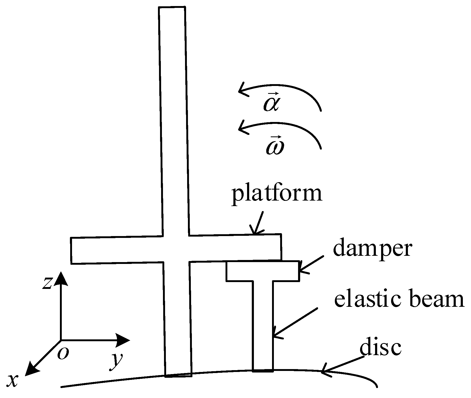
In engineering practice, the blades are set up in a circle around the disc, and the under-platform damper can be installed between two adjacent blades. The whole structure can be considered to be in cyclic symmetry. If the normal pressure between contact surfaces is supposed to be distributed equally between two adjacent blades, then the structural model of under-platform damper, as used in this paper, can be described as in
Figure 1, where the
orthogonal coordinate system (called the moving coordinate system) is defined in accordance with the axial (
, along to the angular velocity direction of the blade), tangential (
), and radial (
) directions. The coordinate system is attached to the bladed disc and rotates with it. A static coordinate system fixed to the ground is defined.
When the rotation of the bladed disc is considered, firstly the vibration stress of the blade mainly depends on its relative displacement (response) to the bladed disc, and the relative displacement should be studied instead of absolute displacement. Secondly, at the rotating state the variation of the convective inertial force and Coriolis inertial force leads to the change of normal pressure and tangential force, which has a significant influence on the damping effects of the damper and the dynamic characteristics of the blade. To study the influence of bladed disc’s rotation and improve the accuracy of analysis of the damper, an approximation method for the dynamic response of the blade relative to the bladed disc (moving coordinate system) has been proposed in this paper by combining the theories of compositive motion and dynamics. Compositive motion describes the motion of a moving body relative to different coordinate systems. The response before steady-state could be defined as the transient response. With this method, the convective inertial force and Coriolis inertial force are considered in dynamic equations; the properties of the system solution are derived; and the vibration-damping law of the steady-state response and the transient response of the blade are studied. Some new conclusions about the damping characteristics of the turbine blade with an under-platform damper were obtained, which will be useful in the damper design in engineering practice.
3. Numerical Simulation
Referring to the engineering, the angular acceleration of the bladed disc increases from 0, and then decreases to 0 after it reaches the top value. The fourth-order Runge–Kutta algorithm was used to compute the relative vibration responses and study the influence of bladed disc’s rotation on the dynamic characteristic of the system. The vibration reduction effect is illustrated. The smooth function is used to describe the angular acceleration as
. The working angular velocity of the bladed disc is
, and the angular acceleration
decreases to 0 after the angular velocity reaches
; then, the bladed disc rotates at a uniform angular velocity
. The steady excitation frequency is
, which equals
.
is the external excitation amplitude. This paper is a mechanistic study. The parameters of the system can be taken from
Table 1. The other parameters are given in the following simulations.
3.1. The Analysis of the Vibration Response’s Characteristics
The two simulations above are typical among the simulating results in this study. When the blade is at steady-state, the motion is periodic from
Figure 5a and
Figure 7a.
Figure 5b and b show the comparison of hysteretic constructive relation of friction force and relative displacement with and without the Coriolis inertial force, and the two constructive relations in the same figure are obviously different. Considering the bladed disc’s rotation, the Coriolis inertial force exists and changes the normal pressure; therefore, the hysteresis loop is not symmetrical. As the normal pressure is a very critical parameter in the dry friction damper’s design, the dynamic characteristics of the system will be different with that without considering the Coriolis inertial force. In
Figure 6 and
Figure 8,
is the steady excitation frequency, and only odd multiple frequencies of
and
can be observed. When the mass of the damper, the vibration stiffness of the damper, and the amplitude of external excitation change, there are no fractional frequencies, nor any bifurcation or chaos with the friction contact surface not being separated. The motion of the system is periodic, and the minimum period of the steady-state response
is equal to that of the external excitation,
.
3.2. The Decision of Steady-State of the Blade
To supply more reference to dry friction platform damper design in engineering, the blade’s vibrational reduction of the steady-state response and the transient response will be studied in the next section; therefore, it is necessary to get the moment
when the system reaches steady-state. In this section, a method for deciding the stable state of the system is proposed: combining the normalized cross-correlation function (NCCF) and the bisection method. The principle of this method is as followings: choosing steady-state response of the last period as a reference sequence, and a response before the last period as the target sequence. Window size
is the length of target sequence which is taken out each time. The correlation coefficient maximum
of reference sequence and target sequence is calculated by the NCCF. The closer that the value of
is to 1, the more that target sequence is in agreement with reference sequence.
is a given parameter, and when
is greater than its value the response can be considered steady-state. The step length
is the moving length of a target sequence each time, and is changeable via the bisection method, which is used to improve the calculation’s accuracy and efficiency. Comparing target sequence from back to front with the reference sequence, the moment
can be obtained when the step length equals to 1. A computational scheme of the mothed is shown in
Figure 9.
When
is 0.999, 0.998, and 0.997, the other parameters are shown in
Table 2. The results are shown in
Figure 10. The difference between the two lines has been amplified by three times for clarity. The moment
when the system reaches steady-state was obtained. When
is 0.999,
satisfies the accuracy requirement.
With , the response of blade before can be defined as , and after can be can be defined as ; therefore, is divided into and .
3.3. The Vibration Reduction Characteristics of the System
Based on the analyses done in
Section 3.1 and
Section 3.2, the influence of damper mass, damper vibration stiffness, and external excitation amplitude on the vibration reduction characteristics of the system are studied in this section. Relevant parameters were set as in
Table 1. The other parameters are given in the following simulation.
is the vibrational power reduction rate of the steady-state response of the blade. As the steady-state response is periodic,
is the minimum period of the steady-state response, which is equal to the period of the external excitation with the value of
. Therefore,
can be expressed as Equation (8).
is the average power-reduction rate of the transient response of the blade, and can be expressed as Equation (9). The relative displacement of the blade without an under-platform damper is
, and the moment when the system without an under-platform damper reaches steady-state is
. Similarly, the response of the blade before
can be defined as
, and after
can be defined as
. The response is divided into
and
.
The maximum values of
and
are
and
respectively, Similarly, the maximum values of
and
are
and
respectively.
is the reduction rate of
and
is the reduction rate of
.
and
are expressed in Equation (10).
3.3.1. The Effect of Damper Mass on the Vibration Reduction
When the working speed is constant, the damper mass has a great influence on the normal pressure. The numerical simulation parameters are taken from
Table 4.
The results are as follows:
In
Figure 11,
and
vary with the increase of the damper mass
; some peaks of
and
are extant. There is a significant reduction of vibrational power with proper damper mass adding to the blade. In
Figure 12,
increases with the damper mass’s increase, while
fluctuates while the damper mass increases.
and
reduce significantly with the proper damper mass adding to the blade. From
Figure 11 and
Figure 12, the laws of
and
varying with
are basically the same, while the laws of
and
are obviously different, as the transient response of the blade is complicated. The maximum values of
and
are smaller than those of
and
with the same parameters.
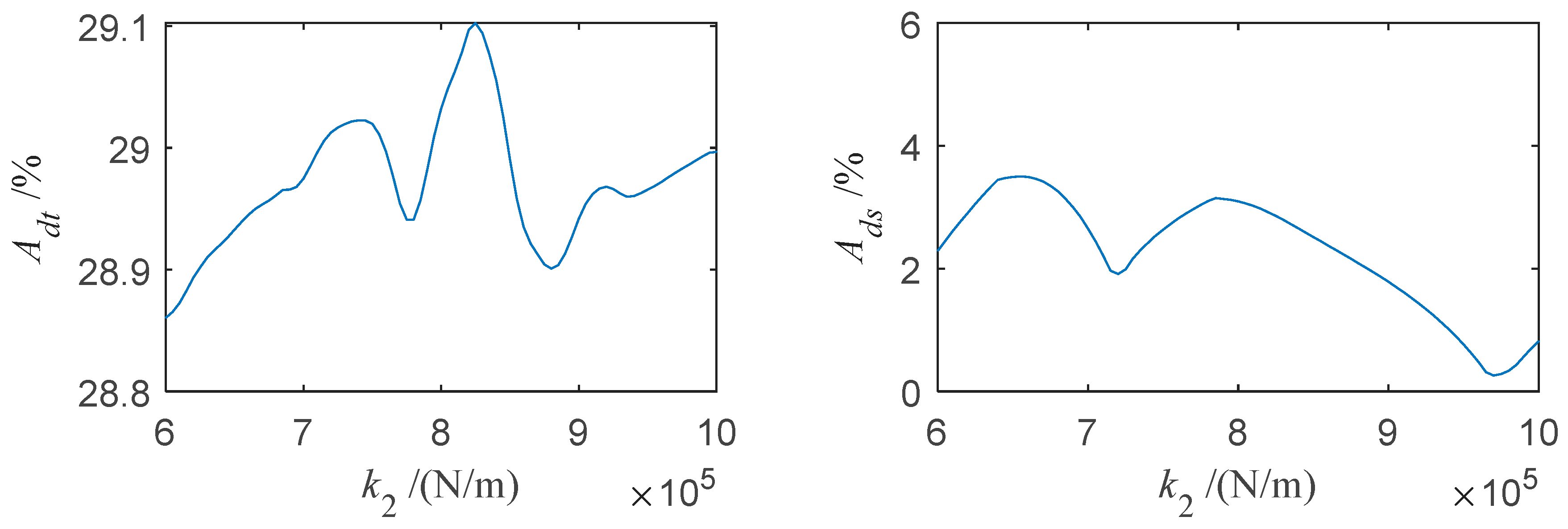
3.3.2. The Effect of a Damper’s Vibrational Stiffness on the Vibration Reduction
The effect of a damper’s vibration stiffness on the vibration reduction of the blade with an under-platform damper was studied. The parameter values are shown in
Table 5.
The results are as follows:
In
Figure 13,
and
fluctuate with the increasing of the damper stiffness
, and there is a significant reduction of vibrational power with proper damper stiffness
. In
Figure 14, the damper stiffness
has an obvious influence on
and
;
and
reduce significantly with the proper damper stiffness. From
Figure 13 and
Figure 14, the laws of
and
varying with
,are basically the same, while the laws of
and
are obviously different. The maximum values of
and
are smaller than those of
and
with the same parameters.
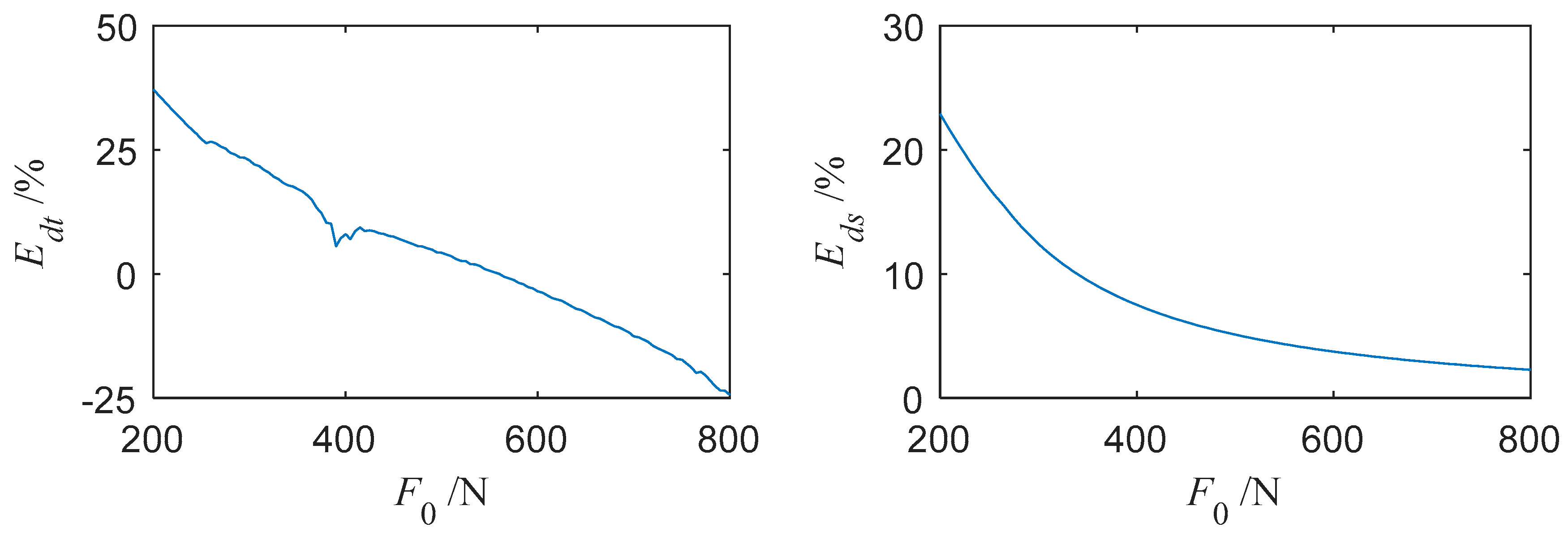
3.3.3. The Effect of External Excitation Amplitude on the Vibrational Reduction
In
Figure 15,
and
basically decrease with the increase of external excitation amplitude
. In
Figure 16,
and
decrease with increasing
. From
Figure 15 and
Figure 16, the increasing external excitation amplitude causes the vibrational reduction effect of the blade to decrease, obviously, and a larger normal pressure would be needed to make the damper work well. The laws of
and
varying with
, are basically the same, as are
and
. Besides,
could be negative with
increasing, which needs to be considered when engineering damper designs.


