1. Introduction
Solid oxide electrochemical cells such as solid oxide fuel cell (SOFC) or solid oxide electrolysis cells (SOEC) are promising future green energy technologies for energy generation and production of hydrogen. SOEC is a solid oxide fuel cell that works in a reversed mode of operation. SOEC and SOFC are typically composed of an anode, cathode, and a solid electrolyte as the three basic cell components, where the SOFC anode becomes the cathode in SOEC when operated in the reverse mode. In order to circumvent the problems associated with high temperature of operation (around 1000 °C), such as degradation during long-term high temperature exposure, ongoing research efforts have been dedicated to developing new material components or tailoring the existing material in order to lower the operation to intermediate temperatures of around 500–800 °C [
1,
2,
3].
For the electrode material, a mixed ionic and electronic conducting material or composite that provides both electronic as well as ionic conductivity as an electrode is needed. The typically studied cathode material for SOEC is Ni/yttrium-stabilized zirconia (YSZ) due to the use of YSZ as a solid electrolyte. YSZ is a typical solid electrolyte that is widely studied due to its high phase stability and high ionic conductivity [
2]. However, at intermediate temperatures (around 500 °C to 800 °C), it exhibits low ionic conductivity [
4]. One promising solid electrolyte is the Sc-doped ZrO
2 (ScSZ) material system that shows higher ionic conductivity than YSZ at lower temperatures [
5,
6,
7]. Hence, using this Sc-based ZrO
2 for both the solid electrolyte and the ionic conducting phase of the electrode may enhance SOEC or SOFC performance at intermediate operating temperatures.
Only limited reports have been published on the combination of ScSZ with Ni as an electrode material. In SOFC mode, electrode materials using Ni and 10Sc1CeSZ:ZrO
2 [
4], Ni/10 mol%Sc
2O
3-1 mol%Y
2O
3-stabilized ZrO
2 [
8], Ni/10Sc
2O
3-1CeO
2-89ZrO
2 [
9,
10], Ni/10 mol%Sc
2O
3-90 mol % ZrO
2 [
10,
11], and Ni/Zr
0.81Sc
0.19O
1.905 [
12] have been reported. For the preparation of these electrode materials, the typical synthesis method involves using a solid state reaction. In our previous work, we employed a modified glycine-nitrate combustion method to synthesize NiO/YSZ [
13]. The use of the glycine-nitrate (g/n) combustion method significantly decreases the sintering temperature and produces a much finer morphology compared with the solid state reaction method [
1,
2,
11]. The microstructure can also be tailored using this combustion process using different g/n ratio [
14].
In this study, a composite of Ni and 8 mol % Sc2O3-stabilied ZrO2 or Ni/ Zr0.84Sc0.16O1.92 electrode material was synthesized using a single-step glycine-nitrate combustion method. The 8 mol % Sc2O3-stabilied ZrO2 with Zr0.84Sc0.16O1.92 composition has not been reported in the literature in combination with Ni as an electrode material, either as an anode for SOFC or as a cathode for SOEC. In addition, three different glycine to nitrate molar ratios (g/n = 0.27, 0.54, and 1.1) were used for the synthesis and the resulting microstructure and conductivity of the sintered samples were investigated.
3. Results and Discussion
Three different samples of 50 wt % NiO and 50 wt % Zr
0.84Sc
0.16O
2-δ compositions using different glycine-to-nitrate ratios were synthesized via a modified single-step glycine-nitrate combustion method. In this study, the composite powder of NiO and ScSZ was synthesized using a single-step combustion method wherein the precursor reagents of these two phases, NiO and ScSZ, were mixed in a glassware, in contrast to our previous work, using a double combustion method wherein one phase was GNP-synthesized first before mixing and combusting the second phase [
13]. This modified single-step preparation using simple and readily available oxides will be advantageous in the facile preparation of this composite electrode material. In order to study the resulting properties of the prepared samples using this single-step approach, the structure, morphology, and conductivity were investigated.
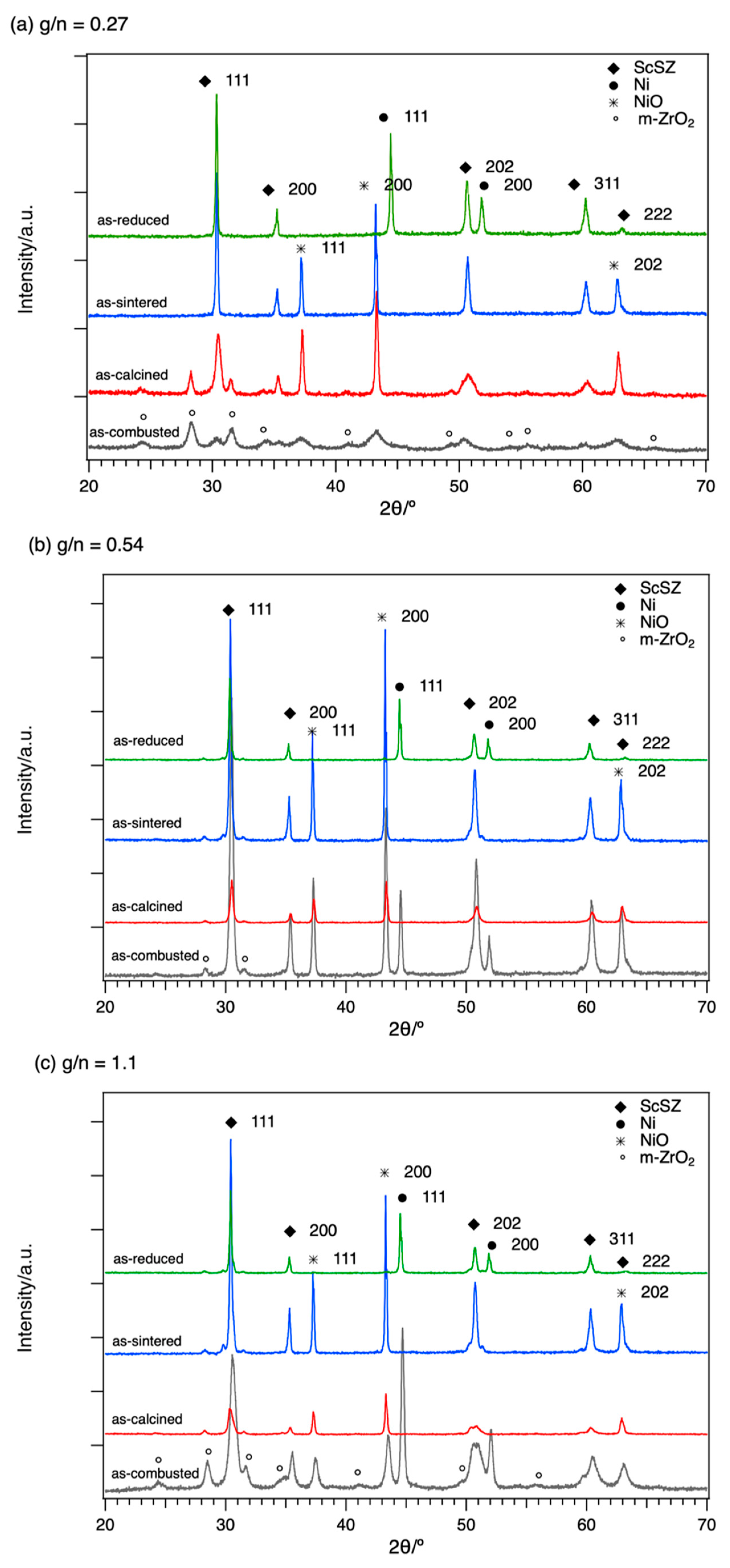
Figure 1 shows the XRD stack patterns for the 0.27 g/n ratio (
Figure 1a), 0.54 g/n ratio (
Figure 1b), and 1.1 g/n ratio (
Figure 1c). For the as-combusted samples, the observed peaks and phases and their relative intensity varied with different g/n ratios. As the g/n ratio increases, the formation of Ni phase increases and the formation of NiO decreases. The observed formation of monoclinic ZrO
2 (m-ZrO
2) is also the main phase for the smallest g/n ratio compared with the already-formed ScSZ phase for the higher g/n ratio.
For the as-sintered samples in all g/n ratios, the phases observed in the XRD pattern were indexed to both cubic phases of NiO (PDF 00-047-1049, a = 4.177 Å) and Zr
0.8Sc
0.2O
1.9 (PDF 01-089-5485, a = 5.091 Å). The calculated lattice parameters for sintered samples of NiO and Zr
0.84Sc
0.16O
1.92 are 4.186 Å, 4.184 Å, and 4.1799 Å, and 5.094 Å, 5.093 Å, and 5.090 Å for g/n ratio of 0.27, 0.54, and 1.1, respectively. Compared to the YSZ with a lattice parameter of 5.141 Å (PDF 01-083-9463), the lattice parameter of ScSZ is smaller due to a smaller ionic radius of Sc (0.885 Å) compared to Y
3+ (1.1 Å) into the Zr
4+ (0.92 Å) lattice site [
13,
15].
The room temperature XRD patterns of the reduced samples are shown in the topmost pattern in
Figure 1a–c. It can be observed that the NiO peaks completely disappear with the formation of the metallic Ni phase. The observed Ni phase can be indexed to cubic Ni (PDF 00-004-0850) with a lattice parameter of 3.529 Å, 3.529 Å, and 3.527 Å for g/n ratios of 0.27, 0.54, and 1.1, respectively.
Figure 2 reveals the porous microstructures of the as-sintered bulk pellets of NiO/ScSZ (
Figure 2a–c) and reduced Ni/ScSZ (
Figure 2e,f) at all g/n ratios. It can be observed that the smallest g/n ratio is denser compared with the other two g/n ratios for the as-sintered composites. Upon reduction of these samples to obtain the Ni/ScSZ, the dense and agglomerated particles then revealed a more porous channel or separation in between the grains due to volume reduction and shrinkage when oxygen is released upon reduction of NiO to Ni. From the observed results, the 0.27 g/n ratio showed a more desirable homogeneous porous morphology compared with the other prepared samples.
In order to investigate the morphology and composition of the unreduced NiO/ScSZ and the reduced Ni/ScSZ with a 0.27 g/n ratio sample, EDS elemental mapping was performed and the results are shown in
Figure 3. As shown in the figure, the NiO and ScSZ ceramics are well mixed in a micron-range distance throughout the sample. The NiO phase is also about 1 micron in size. For the reduced Ni/ScSZ EDS mapping, we observed that there is agglomeration of Ni in the map, which is situated in the vicinity of the connected grains of ScSZ.
Although from
Figure 3, the Ni phase seems to agglomerate, the high magnification SEM images in
Figure 4 clearly reveal that some nanoparticles of Ni are attached at the surfaces of the micrograined size ScSZ apart from the agglomerated ones. These Ni nanoparticles can be observed as fine yellow dots in the EDS mapping in
Figure 3. This particular morphology may be important in increasing the triple-phase boundary (TPB) reaction sites. For SOEC applications, the TPB is an important site as this is a region of contact for the steam gaseous phase, ion conducting electrolyte phase, and electronic conducting electrode phase and where the reaction occurs. For this particular electrode material for SOEC, ScSZ is the ion conducting phase, the pore is where the gaseous steam flows in, and Ni is the electron- conducting electrode phase and a catalyst. Hence, the rate of the chemical reaction is proportional to the number of these active TPBs. Though the Ni particles appeared to be somewhat agglomerated, as shown in the EDS map in
Figure 3, there are scattered Ni nanograins or nanoparticles situated at the surfaces of ScSZ grains, as revealed in
Figure 4. Although the Ni nanoparticles are not connected, if electronic conductivity exists within the electrode, or such nanoparticles are connected or can be connected to the current collector, these nanoparticles that also act as a catalyst may play an important role and may contribute to the active TPBs. From the conductivity results in this study, it seems that the total conductivity of the electrode (Ni/ScSZ) is dominated by electronic conduction with the low activation energy (Figure 6). Hence, the observed Ni nanoparticles may be advantageous. Further study is needed to investigate the activity of these nanoparticles and if they will contribute to active TPBs [
16].
The Arrhenius-type plots of the total conductivities of NiO/ScSZ samples with different g/n ratios under Ar and O
2 gas flow environments, and under a Ar/5%H
2 gas flow environment, at a 500–700 °C operating temperature range are shown in
Figure 5 and
Figure 6, respectively. The conductivities were calculated based on the results of the EIS measurements, wherein the resistance observed can be related to the conductivity with the following equation:
where the resistance (
R) taken from EIS Nyquist plot can then be converted to conductivity (
σ) using the cross-sectional area (
A) and thickness (
t) of the sample pellet. As shown in
Figure 5, under O
2 gas flow environment, the samples showed higher total conductivity compared to the Ar gas flow, which is possibly due to the increase in the oxide ion conductivity contribution from ScSZ and/or other defect associations with the NiO phase under the oxidizing atmosphere. Since conductivity is related to the concentration of the mobile oxide ions and its mobility, the concentration may be depleted under pure Ar gas flow by the creation of oxygen vacancies, dictated by the charge balance of Sc
3+ doping into the Zr
4+ cationic site in the ZrO
2 lattice structure. Hence, the calculated activation energy (Ea) under pure Ar gas is higher compared to O
2 gas flow environment. The doping of Sc
3+ on the Zr
4+ lattice site is given in Equation (2) using the Kroger-Vink notation:
Among the g/n ratios, 0.27 showed the highest total conductivity. At 700 °C, the total conductivity of the 0.27 g/n sample was 4.5 × 10⁻³ S/cm and 1.2 × 10⁻² S/cm under Ar and O2 gas flow environments, respectively. The calculated activation energies are 1.23 eV, 1.10 eV, and 1.16 eV under Ar and 0.57 eV, 0.40 eV, and 0.51 eV under O2 gas flow for g/n ratios of 0.27, 0.54, and 1.1, respectively.
Using the 2-electrode configuration in the EIS measurements, the calculated total conductivities of the reduced samples in Arrhenius-type plot are shown in
Figure 6. The g/n ratio of 0.27 has almost twice the conductivity compared to the other samples. The total conductivities at 700 °C are 7.66 × 10
−2 S/cm, 4.03 × 10
−2 S/cm, and 3.27 × 10
−2 S/cm for 0.27, 0.54, and 1.1 g/n ratios, respectively. The reduced Ni/ScSZ samples has higher total conductivity than NiO/ScSZ. Although, there are only few or no reports for the total conductivity of Ni/ Zr
0.84Sc
0.16O
1.92 with 1:1 wt % composition, the conductivity is lower if compared to the reported Ni/YSZ cermet, which is about 300–1000 S/cm [
17,
18]. This may be due to the limitation of the EIS measurement employed in this study compared to the four-point probe direct current (DC) technique. With the same EIS measurement, another study reported an electrical conductivity of 1.58 S/cm at 900 °C for Ni/YSZ [
19]. In addition, the lower total conductivity observed in this study for Ni/ScSZ may be due to the more porous nature of our reduced sample. For thin film of Ni/10ScSZ with 40 vol % Ni, an electrical conductivity of 300 S/cm at 700 °C was reported using the four-point probe DC technique [
11]. Hence, our future study will involve further characterization of Ni/ScSZ using the four-point probe DC technique and to investigate the ionic and electronic contributions to the total conductivity.
In order to investigate the structural change in ScSZ in the Ni/ScSZ cathode composition, in-situ high-temperature XRD was conducted.
Figure 7 shows the in-situ XRD stack patterns of the reduced Ni/ScSZ sample for the 0.27 g/n ratio under a A5/5%H
2 gas flow. The pattern revealed that ScSZ with the Zr
0.84Sc
0.16O
1.92 composition can retain its cubic phase structure as observed from the XRD results when subjected to 500–800 °C operating temperatures.
Figure 7b shows the 111 peaks, and the pattern suggested a cubic phase retention at these intermediate temperatures. There is a remnant formation of NiO due to possible oxidation of the reduced Ni inside the in-situ high temperature XRD sample chamber apparatus due to remaining oxygen inside the apparatus that was not vacuumed.
Figure 8 shows the calculated lattice constant change in ScSZ and Ni, which revealed a slight increase in the cubic lattice constant at 500–800 °C. At room temperature, the lattice constant calculated is 5.09 Å and 3.53 Å for ScSZ and Ni, respectively.
