1. Introduction
Single-side cantilevered rotor systems are widely used in various types of rotating machinery, such as flue gas turbines and pumps, and play important roles in the military and civil engineering fields. These systems are mainly composed of an impeller, a shaft, a bearing housing, bearings, a coupling, and a driving end [
1]. For the application of this kind of rotating machinery, there are strict requirements on the accuracy of the installation. Therefore, it is important to ensure system stability and safety in order to avoid major accidents. The main threat to the system is vibration [
2].
The excitation sources of vibration mainly come from the rotor system and external excitations. The excitation sources of the rotor system include rotor unbalance, misalignment, and friction [
3,
4,
5]. External excitations are mainly caused by the impact load and pulsation excitation of the fluid. When the excitation frequencies are close to the natural frequencies of the system, the resonance occurs in the system, causing unpredictable losses.
With the rapid development of the single-side cantilevered rotor system, the vibration problems have become increasingly prominent. These problems pose a huge threat to safety production and economic benefits. In actual civil and military equipment, rotor systems often vibrate due to unbalance, resulting in impeller fracture, seal failure, bearing damage, valve failure, pipeline leakage, and loose foundation [
6]. These faults cause equipment damage or even major safety accidents, along with unpredictable personal injury to users. So, it is necessary to control the vibration of the unbalanced single-side cantilevered rotor.
The vibration mechanism of the unbalanced single-side cantilevered rotor system has already been researched by many scholars. According to the obtained theory, the vibration control of the system is divided into four types: structural modification, vibration absorption, vibration isolation, and vibration damping. At the same time, the vibration control method is divided into two types: active and passive control. Active control refers to the use of the sensor to collect signals and feedback for the controller to drive the damper to reduce vibration. Passive control refers to vibration control that can be performed without additional controllers and input energy [
7].
Active control of the unbalanced single-side cantilevered rotor system includes: (1) using active control to change the natural frequency of the system to avoid the resonance region to achieve vibration control [
8] such as installing the mass on the shaft end of the system and changing the position of the mass by PD control. However, when the mass block is applied, the unbalanced excitation of the rotor system will increase, causing the shaft to bend [
9]; and (2) using active control to apply external force that moves in the opposite direction to the exciting force, thereby achieving good vibration control such as applying external force at the impeller of the system through proportional gain feedback control. But this may result in insufficient installation space and increase the amplitude of the vibration [
10]. Also, other researchers used suspension bearings to change the stiffness of the support and isolate the vibration transmission to the bearing to protect it, but the reduced stiffness of the suspension structure limits the range of allowable speeds and cannot be used beyond that range [
11]. Therefore, active control has relatively large limitations, and still needs further development for practical applications.
Passive control of the system includes: (1) using the squirrel-cage squeeze film damper to reduce vibration, but this takes up a lot of space and has serious nonlinearity, easily causing a nonlinear response. Bistable phenomena and lock-up phenomena occur when the rotor passes a critical speed [
12]; (2) using a metal rubber damper to reduce vibration, but this has almost no damping effect at noncritical speeds [
13]; (3) using friction dampers to create frictional energy between metals, but their disadvantages are weak supporting capacity and poor temperature stability, and the material cannot be restored to its original state after yielding [
14]. These methods described above also have great limitations.
In practical industrial situations, due to space constraints and limitations of working conditions, passive control is still required as the main vibration control method. However, passive control has problems such as nonlinearity, installation space, and small vibration reduction range. Therefore, in view of these problems, this paper designs a novel integral squeeze film bearing damper that has a damping effect on a wide frequency range. Moreover, it is segmented, which eliminates the problem of oil film nonlinearity. And it has a simple structure which greatly saves installation space. The novel integral squeeze film bearing damper (ISFBD) is less common in the vibration control of an unbalanced single-side cantilevered rotor system. In this study, vibration control research of this novel ISFBD shows that it provides good theoretical support and a feasible vibration control scheme for the systems in industry.
In this paper, the vibration damping characteristics of the novel integral squeeze film bearing damper are analyzed. The influence of installation position and quantity of the novel ISFBDs on the stability, energy distribution, and vibration control of the unbalanced single-side cantilevered rotor system were numerically calculated. At the same time, a vibration control platform was built to verify the vibration control effect. The results show that different installation positions and quantities have different effects on stability, energy distribution, and vibration control of the system. When two novel ISFBDs are installed at the same time, the vibration control effect is best.
2. Materials and Methods
2.1. Theoretical Modeling of Integral Squeeze Film Bearing Damper
The structure of the integral squeeze film bearing damper is mainly divided into four parts: an outer flange, an elastic body, a squeeze film area, and an inner flange. The outer flange is fitted and fixed to the bearing housing. The inner flange fits snugly against the outer ring of the rolling bearing. The elastic body can change the stiffness of the system, and its structure is similar to the elastic support and has the function of vibration isolation. The squeeze film area can produce a squeezing film effect to generate damping and dissipate vibration energy. These special structures achieve the purpose of vibration control, as shown in
Figure 1. The two main structures are theoretically modeled below.
First, the stiffness damping model of the integral squeeze film bearing damper is shown in
Figure 2. When it was subjected to an external force of
, the vibration isolation function of the elastic body was analyzed [
15,
16,
17,
18].
We made the following assumptions: (1) the elastic body is unitized; (2) the structural damping of the elastic body is neglected; (3) the bearing housing is considered as a rigid body.
For the vibration isolation structure dynamics, there is the following equation:
Then, the displacement of the bearing housing is:
where s represents the frequency ratio, that is,
.
The force that can be transmitted to the bearing housing is:
The force transfer coefficient is then obtained as follows:
It can be seen that when , the elastic body begins to exert the vibration isolation effect, so the exciting force received at the journal is isolated to prevent transmission to the bearing housing and protect the stability of the rotor system.
A damping dissipation theoretical model diagram of the squeeze film area is shown in
Figure 3. The squeeze film area of the integral squeeze film bearing damper can dampen vibration control and dissipate the energy of vibration [
19,
20].
The following assumptions were made for the damping fluid: (a) incompressible Newton fluid is used; (b) laminar flow thin film is used; (c) there is no slip at surfaces; and (d) there is no inertia effect or other external body forces.
The oil film of the novel integral squeeze film bearing damper was analyzed, and the Reynolds equation was used for model analysis [
21,
22]:
where
R is the radius of the squeeze film zone,
p is the oil film pressure,
μ is the damping fluid viscosity coefficient,
z is the axial coordinate, and
θ is the circumferential coordinate.
Since the novel i damper has a seal at both ends for oil seal, it is considered that there is no pressure flow in the axial direction, that is
. Then Equation (5) can be simplified to:
Performing one and two integrals on
, respectively, we can obtain:
where
C is the gap, and
ε is the eccentricity.
The Sommerfeld is applied, that is:
Using Equation (9), we can derive:
Substituting the Sommerfeld equation for Equation (8) gives:
When
θ = 0 and
θ = 2π, while
p (0) =
p (2π), it can be obtained by Equation (11):
Then, we can get the integral constant:
Since the oil supply pressure is environmental pressure, when
θ = 0,
p = 0, A
2 = 0. Then the oil film pressure is:
The oil film is a full oil film without cavitation, and the integration is from 0 to 2π, then the radial oil film reaction force is:
It can be determined that the integral squeeze film bearing damper has no radial oil film reaction force.
The circumferential oil film reaction force:
Then we can get the damping coefficient as:
where μ = 7.03 × 10
−3 N·s/m
2 (this depends on lubricant itself),
L = 0.017 m,
R = 0.03 m, and
C = 0.0005 m (these three variables are the design parameters of the ISFBD itself). And ε =
C/
R ≈ 0, this value is very small and can be neglected, so 2 + ε
2 ≈ 2 and 1 − ε
2 ≈ 1. From this, the damping coefficient of the integral squeeze film bearing damper can be calculated to be 309.8 N·s/m.
2.2. Theoretical Structure Modeling of Unbalanced Single-Side Cantilevered Rotor System
A simplified model of the unbalanced single-side cantilevered rotor system is shown in
Figure 4. The following assumptions were made during the analysis: (1) there is an elastic massless shaft; (2) regardless of the torsional vibration of the shaft, the angular velocity of the shaft is constant; (3) the axial length of the disc is neglected, and the imbalance of the disc is located on one side plane; and (4) the stiffness and damping of the integral squeeze film damper are isotropic [
23,
24,
25,
26].
It is assumed that the lateral displacement the rotation angle of the geometric center of the cantilevered disk in the
x, y directions are
respectively. The lateral displacements of ISFBD A and ISFBD B in the
x, y directions are
respectively. The integral squeeze film bearing damper mass and cantilevered disk mass are
and
m, respectively. The polar moment of inertia and diameter moments of inertia of the cantilever disk are
and
, respectively. The distance from damper A to the motor is
l. The distance between the two dampers is
b. The cantilevered distance is
a and the angular velocity of rotation is
Ω. The disk eccentricity is
, the initial phase angle is
, and the phase difference of the rotational dynamic deflection is
. Therefore, the kinetic energy of the disc is:
The potential energy of the disc is:
The dissipative energy of the disc is:
where
g is gravitational acceleration, and
and
are the lateral movement of the cantilever disk and the damping coefficient of the diameter rotation, respectively.
Similarly, the kinetic, potential, and dissipative energy of integral squeeze film bearing dampers A and B are:
where
k represents the stiffness of the damper in the
x and
y directions, and
c represents the damping coefficient of the damper.
The elastic potential energy of the shaft is:
where
,
are the actual deflections of the shaft at the center of the cantilevered disk.
is the stiffness influence coefficient matrix of the shaft. According to the Lagrange equation of the non-conservative system:
where
T,
V, and
H are the kinetic, potential, and dissipative energy of the system, respectively;
is the system-independent generalized coordinates; and
,
are the generalized forces to which the system is subjected.
where
is the mass of the integral squeeze film bearing damper, and
(
i,j = 1,2,3,4) is the stiffness of the system. This part of the theory provides theoretical guidance for subsequent finite element analysis.
2.3. FEM of Integral Squeeze Film Bearing Damper
From
Section 2.2, the unbalanced single-side cantilevered rotor system was modeled as shown in
Figure 5. The model simulates the installation of the integral squeeze film bearing damper by modifying the stiffness and damping of the support. The following 4 working conditions were designed to investigate the influence of the position and quantity of the integral squeeze film bearing dampers on the stability and energy distribution of the system: (1) the rigid support is installed in the bearing housing (working condition 1); (2) damper is installed in the bearing housing near the motor end, and the bearing housing away from the motor end is still rigidly supported (working condition 2); (3) rigid support is installed in the bearing housing near the motor end, and an bearing damper in installed in the bearing housing away from the motor end (working condition 3); and (4) two dampers are installed in both bearing housings (working condition 4); The purpose of working conditions 1, 2, and 3 is to investigate the effect of the installation position on the unbalanced single-side cantilevered rotor system. The purpose of working conditions 1, 2, 3, and 4 is to investigate the effect of the number of installations on the rotor system.
The model was established to study the effect of support stiffness on the first order critical speed, as shown in
Figure 6 and
Table 1. It can be found that when the support stiffness exceeds 1.5 × 10
7 N/m, the first order critical speed of the rotor system does not increase with the increasing stiffness. Therefore, it can be known that the stiffness of the integral squeeze film bearing damper needs to be designed to be less than 1.5 × 10
7 N/m to effectively reduce the first order critical speed of the system.
When using Equation (29), in its first formula and the second formula, all of the damping parameters are set to 0. The finite element model calculates the corresponding critical speed by setting different support stiffness levels, and then connects all the points of the critical speeds corresponding to each stiffness level to obtain the curve shown in
Figure 6.
In this paper, considering that the support stiffness is too low, the damper can quickly achieve fatigue failure. Therefore, the design of the ISFBD used ANSYS for static analysis, as shown in
Figure 7. First, we should calculate the stiffness of the shaft, as shown in
Figure 7a. The shaft has a stiffness of 1.0 × 10
8 N/m. According to the machinery vibration and rotordynamics theory, the stiffness design range of ISFBD is one or two orders of magnitude lower than the shaft stiffness. So the ISFBD has a stiffness of 5.6 × 10
6 N/m. It can be seen from the displacement contour that the main deformation of the displacement is concentrated on the S-shaped elastic body.
Stress analysis was performed on the novel integral squeeze film bearing damper, and the analysis type was von-Mises stress, as shown in
Figure 8. It can be found that the damper has no obvious stress concentration, uniform stress distribution and good protection in terms of strength.
Through the analysis of the above displacement contour and stress contour, the novel integral squeeze film bearing damper can ensure a safe and healthy service life. And this issue can change the first order critical speed of the unbalanced single-side cantilevered rotor system.
2.4. Experimental Validation of Integral Squeeze Film Bearing Damper Treatment
Vibration control of an unbalanced single-side cantilevered rotor system is achieved by mounting ISFBDs at the bearing housings. The structural parameters of the integral squeeze film bearing damper will significantly affect the vibration control effect of the unbalanced single-side cantilevered rotor system. In order to verify the damping performance of the damper, a vibration control platform was established as shown in
Figure 9.
The platform is mainly composed of an unbalanced single-side cantilevered rotor system and a vibration monitoring part. The vibration monitoring part of the hardware mainly includes:
Sensor: The sensors used in this paper include photoelectric and eddy current sensors. The photoelectric sensor is used for speed measurement, and its measurement range is from 0.3 Hz to 10 kHz, output current is less than 30 mA, the resolution film number is greater than 0.5, the application distance is 1–2000 mm, and the rotational speed measurement is stable. The eddy current sensor is used to measure the vibration displacement of the shaft. The measuring range is up to 2 mm, the sensitivity is high (it has a sensitivity of 8 mV/μm, a resolution of 1 μm, and a linearity of 1.5%), and the measurement is accurate.
Proximitor: The proximitor is an electronic signal processor. The internal coil of the eddy current sensor provides high-frequency alternating current. And changes of the sensor parameter due to changes of displacement can be detected.
Signal acquisition system: The signal acquisition system consists of a signal collector and a computer. The system is used to measure and analyze the received vibration signals. The signal collector has eight channels and can change the sampling frequency and sampling points as needed. It has many analysis modules, such as time domain and frequency domain spectra.
In this experiment, the photoelectric sensor was used for speed acquisition, and the eddy current sensor was used to monitor the displacement vibration of the shaft near the unbalanced single-side cantilevered disk. We set the number of sampling points to 512 and the sampling frequency to 1 KHz in the software. Channels 1 and 2 were used for selecting and receiving signals. The time domain and the frequency domain spectrum are analyzed to explore the vibration control of the integral squeeze film bearing damper.
As shown in
Figure 10, the integral squeeze film bearing damper was mounted between the bearing outer ring and the bearing housing. Experimental comparisons were made by replacing the integral squeeze film bearing damper and the rigid support. The rigid support is a rigid ring of the same size and material as the damper.
The set of experiments consisted of four working conditions, corresponding to the finite element model in
Section 2.3. Before the experiment, the rotor system was dynamically balanced. And an unbalanced mass of 0.15 g·m was applied on the cantilevered disk.
3. Results
3.1. Influence on Stability by Integral Squeeze Film Bearing Damper
According to the finite element model in
Section 2.3, the cantilevered disk of the rotor system has an unbalanced mass and the system passes the first order critical speed. The influence of the four working conditions on the stability of the unbalanced single-side cantilevered rotor system is shown in
Figure 11. The closer to the cantilevered disk the ISFBD is installed, the better the system stability. When there are more installed integral squeeze film bearing dampers installed, the system stability is improved.
As shown in the curves of the rotational speed-logarithmic decay obtained in
Figure 11a–d, there are actually four curves in each figure. The curves from the bottom to the top in each figure are the first-order forward precession, the second-order forward precession, the third-order forward precession and the third-order backward precession. Since the rotor systems only pass the first-order critical speed, we just look at the bottom curve. It can be known whether the logarithmic attenuation curve with a threshold less than 0 is the basis for judging whether the unbalanced single-side cantilevered rotor system is stable. And the greater the logarithmic attenuation value, the more stable the rotor system.
Figure 11a has lots of discrete points indicating the instability of the rotor system. In addition, the logarithmic attenuations of
Figure 11b–d are greater than 0, so they are stable systems, where the stability of (d) is better than (c), and the stability of (c) is better than (b).
It can be seen from the simulation of the four working conditions that the single-side cantilevered rotor system is unstable when there is an unbalanced amount in the cantilevered disk, as shown in
Figure 11a.
However, when the integral squeeze film bearing damper is installed in the single-side cantilevered rotor system, the system is stable due to the stiffness and damping provided by the damper. It can be seen from
Figure 11a–c that the position of the damper has an influence on the stability of the unbalanced single-side cantilevered rotor system. The closer the damper is installed to the cantilevered end, the better the stability of the unbalanced single-side cantilevered rotor system. It can be seen from
Figure 11a–d that the quantity of bearing damper installations also has an effect on the stability of the system. When dampers are installed at both bearing housings, the stability of the unbalanced single-side cantilevered rotor system is better.
Therefore, when the unbalanced single-side cantilevered rotor system is retrofitted, the integral squeeze film bearing damper should be installed as close as possible to the cantilevered end bearing housing or the quantity of dampers should be increased if possible. These two ways can effectively improve the stability of the unbalanced single-side cantilevered rotor system. When two dampers are installed, the system has the best energy distribution.
3.2. Influence of Integral Squeeze Film Bearing Damper on Energy Distribution
According to the finite element model in
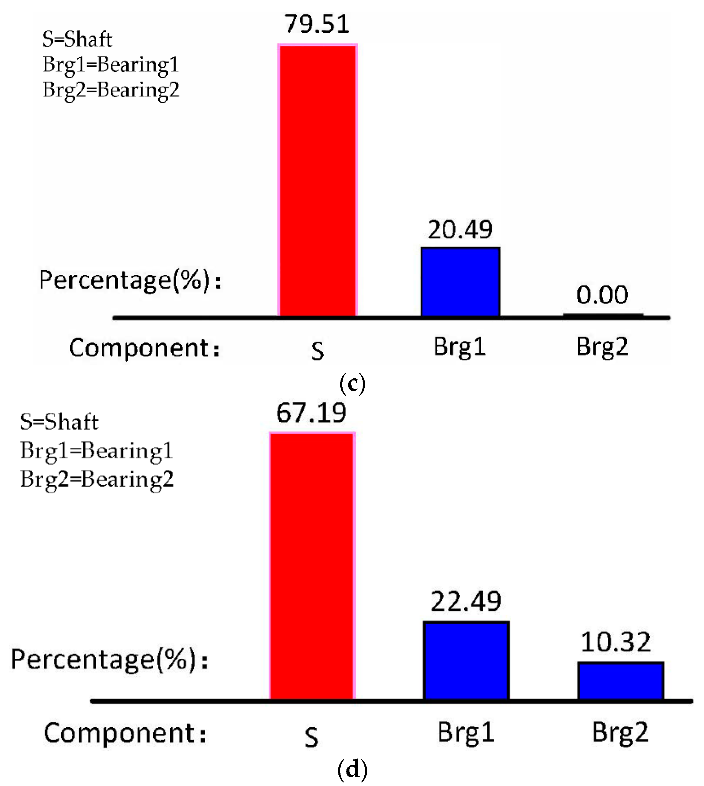
Section 2.3, the energy distribution of the unbalanced single-side cantilevered rotor system corresponding to the four working conditions was analyzed as shown in
Figure 12. ISFBD can effectively share the vibration energy of the system and dissipate energy through its own squeeze film damping effect, making the system safer to operate.
By simulating the four working conditions, it can be known from
Figure 12a that when there is an unbalanced amount on the cantilever disk, 99.99% of the vibration energy of the unbalanced single-side cantilevered rotor system is concentrated on the shaft when it is rigidly mounted, which will make the shaft have larger bending deformation.
The position and quantity of installed integral squeeze film bearing dampers have a large impact on the distribution of system energy. As shown in
Figure 12a–c, the rigid support is mounted close to the cantilevered end and the damper is mounted away from the cantilevered end. Subsequently, it does not distribute the vibration energy of the rotor system.
The integral squeeze film bearing damper installed near the cantilevered end can distribute the vibration energy of the rotor system by 20.49%. It can be seen from
Figure 12a–d that the quantity of dampers also affects the energy distribution of the system. When dampers are installed at both bearing housings, they can share 32.81% of the vibration energy of the rotor system.
Figure 12c,d shows that the ability to share the energy of the bearing damper near the cantilevered end can be improved by installing two integral squeeze film bearing dampers.
Therefore, when designing and installing the system, the right position and quantity should be chosen to allow the integral squeeze film bearing damper to distribute the vibration energy of the system.
3.3. Influence on First Order Critical Speed by the Integral Squeeze Film Bearing Damper
The novel integral squeeze film bearing damper designed in
Section 2.3 has a much lower stiffness than the rigid support and rolling bearing. This results in decreased overall stiffness of the unbalanced single-side cantilevered rotor system, so the critical speed of the system will also change. The effect on the critical speed of the rotor system is explored by changing the installation position and quantity of integral squeeze film bearing dampers. The speed measurement range is from 2200 r/min to 3000 r/min. The displacement response of the shaft at the cantilevered disk is extracted, and the critical speed can be changed under different working conditions, as shown in
Figure 13 and
Table 2.
As can be seen from
Figure 13 and
Table 2, integral squeeze film bearing dampers can reduce the critical speed of the unbalanced single-side cantilevered rotor system. When both supports are rigidly supported, the critical speed is 2673 r/min. When the support away from the cantilevered end is integral squeeze film bearing damper, the critical speed is 2667 r/min. When the support near the cantilevered end is integral squeeze film bearing damper, the critical speed is 2641 r/min. When both supports are integral squeeze film bearing dampers, the critical speed is 2620 r/min.
It can be found that when the support away from the cantilevered end is an integral squeeze film bearing damper, the critical speed is substantially similar to when it is a rigid support. However, when the support near the cantilevered end is an integral squeeze film bearing damper and both supports are integral squeeze film bearing dampers, there are significant critical speed changes. This change in critical speed can effectively avoid resonance and reduce the vibration of the rotor system. This structure can protect the rotor for safe operation.
3.4. Influence of Integral Squeeze Film Bearing Damper on Vibration Control
When there is an unbalanced mass at the cantilevered disk, the unbalanced single-side cantilevered rotor system will strongly vibrate through the first order critical speed, and the amplitude will increase sharply, which will cause the rotor system to fail, resulting in a dangerous operation process. Through the
Section 2.3, the time domain and frequency domain diagrams of the four working conditions of the rotor system were simulated, which can help us predict the vibration control effect in advance. Therefore, it is believed that installing of an integral squeeze film bearing damper at the bearing housing will effectively reduce the amplitude of the unbalanced single-side cantilevered rotor system. We explored the vibration control on the rotor system by changing the installation position and quantity of integral squeeze film bearing dampers. An unbalanced mass of 0.15 g·m was applied to the cantilevered disk as an excitation.
As can be seen from
Figure 13, the vibration amplitude of the rotor system was the largest at the critical speed. The time domain spectrum acquired at 2600 r/min (close to the critical speed) was analyzed for the four different working conditions, as shown in
Figure 14 and
Table 3.
It can be seen from the above graph and table that the theoretical results were basically consistent with the experimental results and the maximum experimental vibration peak-to-peak values at 2600 r/min were as follows: working condition 1, 1885.57 μm; working condition 2, 1826.08 μm; working condition 3, 1500.71 μm; and working condition 4, 1233.42 μm.
Based on working condition 1, the vibration of working conditions 2, 3 and 4 decreased by 3.16%, 20.41%, and 34.59%, respectively. It can be known that if only one integral squeeze film bearing damper is installed, it has a better damping effect when it is installed near the cantilevered end. If two integral squeeze film bearing dampers are installed, they can have a good vibration control effect, which is the best outcome among the four working conditions.
The time domain spectrum of 2600 r/min as shown in
Figure 14 by Fourier transform to obtain the frequency domain spectrum. We still compare the theoretical results with the experimental results in the frequency domain spectrum, and the simulation results were well fitted with the actual experimental results. The damping effect of integral squeeze film bearing damper at 1 × frequency, 2 × frequency, 3 × frequency, and other multiple frequencies was explored, as shown in
Figure 15 and
Table 4.
It can be seen from the experimental results in the above diagram and table that if only one integral squeeze film bearing damper is installed, the 1 ×, 2 ×, and 3 × frequencies have a damping effect. Also, an integral squeeze film bearing damper installed near the cantilevered end has a better effect by up to 21.19%, 41.73%, and 30.97%, respectively. If two integral squeeze film bearing dampers are installed, the 1 ×, 2 ×, and 3 × frequencies have good damping effects that are improved by up to 33.67%, 60.57%, and 50.26%, respectively. It can be seen that in the four working conditions, installing two integral squeeze film bearing dampers has the best vibration control effect on the characteristic frequencies.
4. Conclusions
Through theoretical analysis, numerical analysis, and experimental verification, the following conclusions can be drawn:
The influence of the support stiffness on the critical speed of the unbalanced single-side cantilevered rotor system shows that when the support stiffness is greater than 1.5 × 10⁷ N/m, the critical speed does not change. Therefore, a novel type of integral squeeze film bearing damper is designed. The stiffness of the ISFBD is designed to be 5 × 10⁶ N/m by numerical analysis, which ensures that the stiffness meets the design requirements and ensures the strength of the ISFBD structure.
Through numerical analysis, the influences of ISFBD installation position and quantity on system stability and energy distribution is verified. Studying the installation position shows that installing an integral squeeze film bearing damper near the cantilevered end can make the system more stable, and can share 20.49% of the energy at the support. A study of the quantity of dampers shows that installing two dampers makes the system more stable than installing one damper, while allowing 32.81% of the energy of the system to be shared.
Under the unbalanced excitation of 0.15 g·m at the cantilevered end, it is verified that installing the ISFBD at the appropriate position can change the critical speed of the system and effectively avoid resonance.
At the same time, the quantity and position of integral squeeze film bearing dampers are investigated to reduce the vibration of the unbalanced single-side cantilevered rotor system. The numerical results are in good agreement with the experimental results. By analyzing the time and frequency domains at the given speed, it can be seen that installing the damper near the cantilevered end has a better vibration control effect, which can reach 20.41% in the time domain spectrum. The damping effects of 1 ×, 2 ×, and 3 × frequencies in the frequency domain spectrum are 21.19%, 41.73%, and 30.97%, respectively.
If two ISFBDs are installed, they can reach 34.59% in the time domain spectrum, and the damping effects on the 1 ×, 2 ×, and 3 × frequencies in the frequency domain spectrum are 33.67%, 60.57%, and 50.26%, respectively. This can provide some guidance for practical engineering applications. Installing an integral squeeze film bearing damper close to the cantilevered end or changing the supports to integral squeeze film bearing dampers leads to better vibration control.
Vibration control of the unbalanced single-side cantilevered rotor system using ISFBD needs further research, mainly in the following aspects:
Some conditions were limited and simplified in the process of establishing physical models, and further analysis of the theory and exploration of practical applications is still needed. For example, during numerical simulations and experiments, the effects of vibration on the unbalanced single-side cantilevered rotor system when the system takes in or discharges fluid were not considered.
In the ISFBD structure, the selection and design of stiffness and damping still need further research in order to obtain a more optimized structure and achieve a better damping effect.
Adaptive control studies can be performed on the stiffness and damping of ISFBDs. The differences in vibration control effects between active and passive controls and their respective advantages and disadvantages should be explored in order to apply different types of integral squeeze film bearing dampers for different practical applications.


