An Ultra-High-SMSR External-Cavity Diode Laser with a Wide Tunable Range around 1550 nm

 ,
,
Abstract
:Featured Application
Abstract
1. Introduction
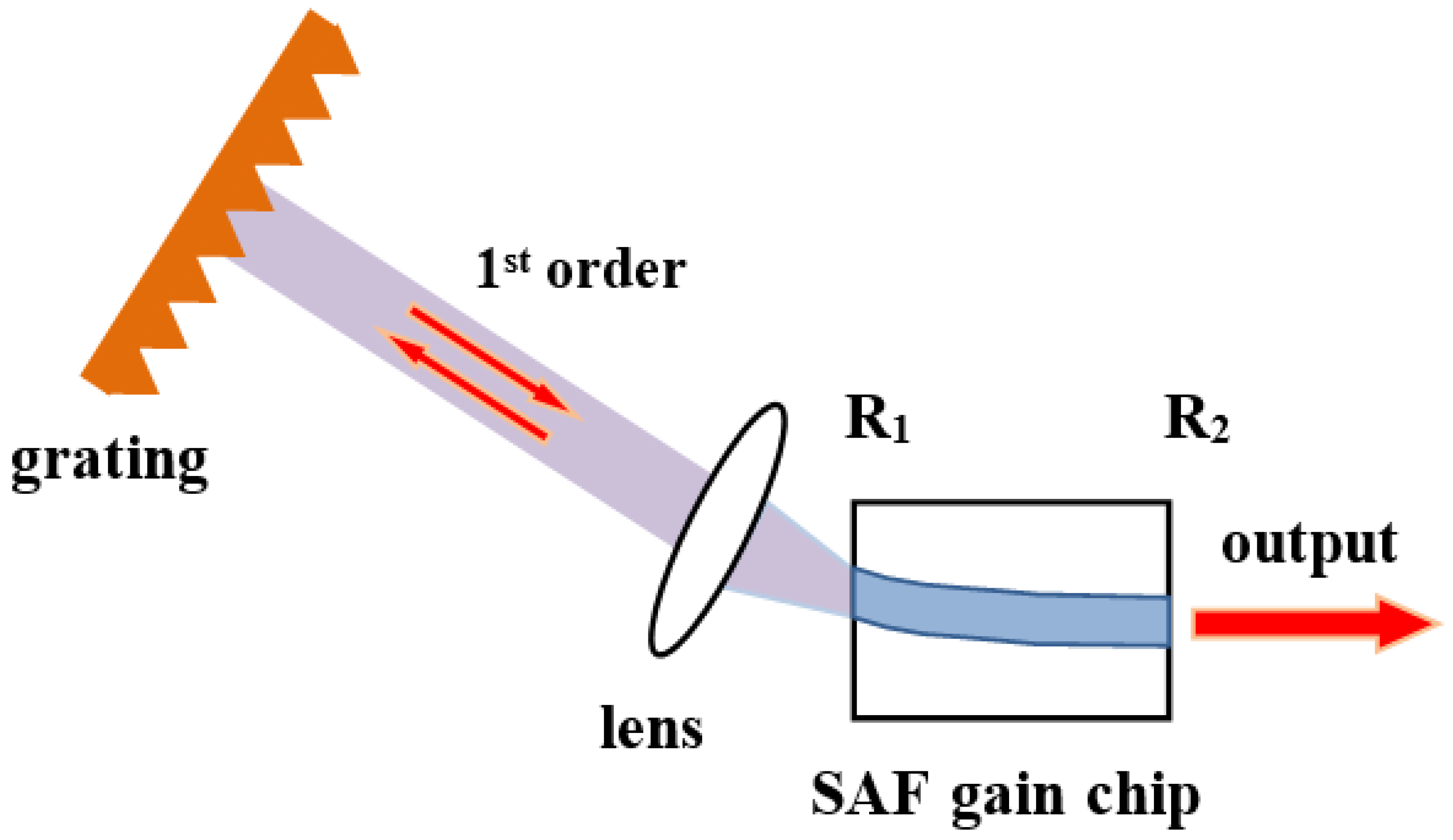
2. Experimental Setup
3. Results and Discussion
4. Conclusions
Author Contributions
Funding
Conflicts of Interest
References
- Phyllips, W.D. Laser cooling and trapping of neutral atoms. Rev. Mod. Phys. 1998, 70, 721–741. [Google Scholar] [CrossRef]
- Bashkansky, M.; Lucke, R.L.; Funk, E.; Richard, L.J.; Reintjes, J. Two-dimensional synthetic aperture imaging in the optical domain. Opt. Lett. 2002, 27, 1983–1985. [Google Scholar] [CrossRef] [PubMed]
- Ma, Y.; Yang, Q.; Tang, Y.; Chen, S.; Shieh, W. 1-Tb/s single-channel coherent optical OFDM transmission over 600-km SSMF fiber with subwavelength bandwidth access. Opt. Express 2009, 17, 9421–9427. [Google Scholar] [CrossRef] [PubMed]
- Zhang, D.; Zhao, J.; Yang, Q.; Liu, W.; Fu, Y.; Li, C.; Luo, M.; Hu, S.; Hu, Q.; Wang, L. Compact MEMS external cavity tunable laser with ultra-narrow linewidth for coherent detection. Opt. Express 2012, 20, 19670–19682. [Google Scholar] [CrossRef] [PubMed]
- Bagnoli, P.E.; Beverini, N.; Falciai, R.; Maccioni, E.; Morganti, M.; Sorrentino, F.; Stefani, F.; Trono, C. Development of an erbium-doped fibre laser as a deep-sea hydrophone. J. Opt. A Pure Appl. Opt. 2006, 8, S535–S539. [Google Scholar] [CrossRef]
- Lu, Y.; Zhu, T.; Chen, L.; Bao, X. Distributed Vibration Sensor Based on Coherent Detection of Phase-OTDR. J. Lightwave Technol. 2010, 28, 3243–3249. [Google Scholar]
- Kitching, J.; Boyd, R.; Yariv, A.; Shevy, Y. Amplitude noise reduction in semiconductor lasers with weak, dispersive optical feedback. Opt. Lett. 1994, 19, 1331–1333. [Google Scholar] [CrossRef] [Green Version]
- Doringshoff, K.; Ernsting, I.; Rinkleff, R.; Schiller, S.; Wicht, A. Low-noise, tunable diode laser for ultra-high-resolution spectroscopy. Opt. Lett. 2007, 32, 2876–2878. [Google Scholar] [CrossRef] [Green Version]
- Chi, M.; Jensen, O.B.; Holm, J.; Pedersen, C.; Andersen, P.E.; Erbert, G.; Sumpf, B.; Petersen, M. Tunable high-power narrow-linewidth semiconductor laser based on an external-cavity tapered amplifier. Opt. Express 2005, 13, 10589–10596. [Google Scholar] [CrossRef]
- Loh, H.; Lin, Y.J.; Teper, I.; Cetina, M.; Simon, J.; Thompson, J.K.; Vuletić, V. Influence of grating parameters on the linewidths of external-cavity diode lasers. Appl. Opt. 2006, 45, 9191–9197. [Google Scholar] [CrossRef] [PubMed]
- Saliba, S.D.; Scholten, R.E. Linewidths below 100 kHz with external cavity diode lasers. Appl. Opt. 2009, 48, 6961–6966. [Google Scholar] [CrossRef]
- Shin, D.K.; Henson, B.M.; Khakimov, R.I.; Ross, J.A.; Dedman, C.J.; Hodgman, S.S.; Baldwin, K.G.; Truscott, A.G. Widely tunable, narrow linewidth external-cavity gain chip laser for spectroscopy between 1.0–1.1 um. Opt. Express 2016, 24, 27403–27414. [Google Scholar] [CrossRef] [PubMed]
- Bagley, M.; Wyatt, R.; Elton, D.J.; Wicks, H.J.; Spurdens, P.C.; Seltzer, C.P.; Cooper, D.M.; Devlin, W.J. 242 nm continuous tuning from a GRIN-SC-MQW-BH InGaAsP laser in an extended cavity. Electron. Lett. 1990, 26, 267–269. [Google Scholar] [CrossRef]
- Fedorova, K.A.; Cataluna, M.A.; Kudryashov, I.; Khalfin, V.; Rafailov, E.U. Broadly Tunable InGaAsP–InP Strained Multiquantum-Well External Cavity Diode Laser. IEEE Photonic Technol. Lett. 2010, 22, 1205–1207. [Google Scholar] [CrossRef]
- Gao, F.; Luo, S.; Ji, H.M.; Yang, X.G.; Yang, T. Enhanced performance of tunable external-cavity 1.5 μm InAs/InP quantum dot lasers using facet coating. Appl. Opt. 2015, 54, 472–476. [Google Scholar] [CrossRef]
- Gao, F.; Luo, S.; Ji, H.M.; Yang, X.Z.; Liang, P.; Yang, T.S. Broadband tunable InAs/InP quantum dot external-cavity laser emitting around 1.55 μm. Opt. Express 2015, 23, 18493–18500. [Google Scholar] [CrossRef]
- Yuan, H.H.; Gao, F.; Yang, T. Ultra-broadband tunable single- and double-mode InAs/InP quantum dot external-cavity laser emitting around 1.65 μm. Opt. Lett. 2018, 43, 3025–3028. [Google Scholar] [CrossRef] [PubMed]
- Wang, Y.; Wu, H.; Zhang, X.; Liu, J.G.; Chen, C.; Wang, Y.B.; Zhou, Y.L.; Liang, L.; Zhang, J.; Qin, L.; et al. 1550 nm external cavity diode laser with enhanced SMSR based on polarization mismatch by grating rotation. Appl. Opt. 2019, 58, 5213–5218. [Google Scholar] [CrossRef] [PubMed]


| Grating | Configuration | Ruling Density (Grooves/mm) | Diffraction Efficiency in the First Order (%) |
|---|---|---|---|
| Grating I | A | 600 lines/mm | 90 |
| B | 17 | ||
| Grating II | C | 1200 lines/mm | 91 |
| (External Cavity Diode Laser) ECDL System | Maximum (Side Mode Suppression Ratio) SMSR (dB) | Tunable Range (nm) | Maximum Power (mW) | |
|---|---|---|---|---|
| ECDL based on InGaAsP/InP MQW laser [13] | 42 | 242 | 45 | |
| ECDL based on InGaAs/InP strained multi-quantum-well laser [14] | 50 | 173 | 81 | |
| ECDL based on InAs/InP quantum-dot laser [15] | - | 104 | 34 | |
| ECDL based on InAs/InP QD laser [16] | - | 140.4 | 6 | |
| ECDL based on InAs/InP QD laser [17] | 20 | 190 (pulsed current) | - | |
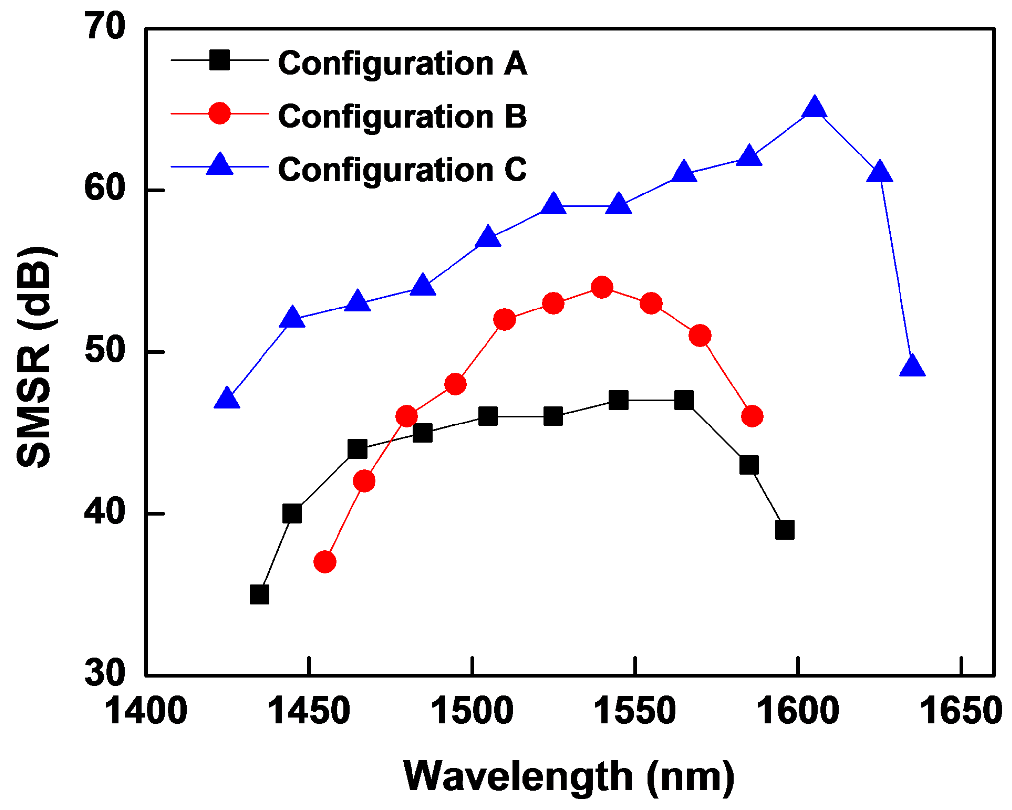
| This work | Configuration A | 47 | 161.2 | 49.9 |
| Configuration B | 54 | 130.9 | 5.5 | |
| Configuration C | 65 | 209.9 | 48.9 | |
© 2019 by the authors. Licensee MDPI, Basel, Switzerland. This article is an open access article distributed under the terms and conditions of the Creative Commons Attribution (CC BY) license (http://creativecommons.org/licenses/by/4.0/).
Share and Cite
Wang, Y.; Wu, H.; Chen, C.; Zhou, Y.; Wang, Y.; Liang, L.; Tian, Z.; Qin, L.; Wang, L. An Ultra-High-SMSR External-Cavity Diode Laser with a Wide Tunable Range around 1550 nm. Appl. Sci. 2019, 9, 4390. https://doi.org/10.3390/app9204390
Wang Y, Wu H, Chen C, Zhou Y, Wang Y, Liang L, Tian Z, Qin L, Wang L. An Ultra-High-SMSR External-Cavity Diode Laser with a Wide Tunable Range around 1550 nm. Applied Sciences. 2019; 9(20):4390. https://doi.org/10.3390/app9204390
Chicago/Turabian StyleWang, Yan, Hao Wu, Chao Chen, Yinli Zhou, Yubing Wang, Lei Liang, Zhenhua Tian, Li Qin, and Lijun Wang. 2019. "An Ultra-High-SMSR External-Cavity Diode Laser with a Wide Tunable Range around 1550 nm" Applied Sciences 9, no. 20: 4390. https://doi.org/10.3390/app9204390