Article

Study on the Dynamic Characteristics of a Hydraulic Continuous Variable Compression Ratio System

Key Laboratory of Advanced Manufacturing Technology, Ministry of Education, Guizhou University, Guiyang 550025, China
*
Author to whom correspondence should be addressed.
Appl. Sci. 2019, 9(21), 4484; https://doi.org/10.3390/app9214484
Submission received: 11 September 2019 / Revised: 18 October 2019 / Accepted: 21 October 2019 / Published: 23 October 2019
(This article belongs to the Special Issue Advances in Mechanical Systems Dynamics)

Abstract

:
Variable compression ratio (VCR) technology has long been recognized as a method for improving the engine performance, efficiency, and fuel economy of automobiles, with reduced emissions. In this paper, a novel hydraulic continuous VCR system based on the principle of an adjustable hydraulic volume is introduced. The continuous variable compression ratio of the VCR system is realized by the hydraulic system controlling the rotation of the eccentric pin to change the positions of the top dead center (TDC) and the bottom dead center (BDC). The construction of the mathematical model and simulation model of the VCR system is also presented in this paper. The piston motion characteristics, flow characteristics, and pressure characteristics of the hydraulic system of the VCR system at different engine speeds and adjustment quantities are studied by simulation in this paper. The simulation results show that the VCR system has a fast response and good dynamic characteristics, and can achieve continuous adjustment of the compression ratio.

1. Introduction

Due to the increasingly severe energy crisis and environmental pollution [1], increasingly stringent emission and fuel economy standards have been proposed by many governments [2], which make improving the efficiency of engines an important topic. In China, the limit of fuel consumption will be 5 L per 100 km up to 2020 [3]. In the United States and Japan, passenger vehicles will have to achieve 23 km/L on average from 2025 [4]. Additionally, in Europe, the CO2 emission limit will be 60 g per kilometer from 2025 [5]. The major challenges in the automotive industry are improving the engine efficiency by reducing the fuel consumption and reducing the engine emissions to meet the emission standards. Researchers have found that variable compression ratio (VCR) technology can provide further degrees of freedom to optimize the engine performance for various operating conditions. At low power levels, the engine operates at a higher compression ratio to capture the benefits of a higher thermal efficiency, while at high power levels, the engine operates at a lower compression ratio to prevent knocking. By continuously changing the compression ratio, an engine enables the optimum combustion efficiency to be obtained at all engine speed and load conditions, resulting in a better engine performance, lower fuel consumption, and lower exhaust emissions [6,7,8].
Owing to the advantages of VCR, researchers and manufacturers have devoted much effort to studying VCR technology. According to a survey, thousands of patents all over the world have been published, and more than 120 different kinds of VCR mechanisms have appeared, since 2000, and the numbers have kept increasing rapidly from 2013 up to the present date [3,8]. Forced Evolution Virus (FEV) has developed a VCR engine in which the crankshaft bearing is carried in an eccentrically mounted carrier that can rotate to raise or lower the top dead center (TDC) positions of the pistons in the cylinder. The compression ratio of FEV’s VCR engine is adjustable by varying the rotation of the eccentric carrier [9,10]. Nissan uses a multi-link system to achieve VCR by inserting a control linkage system between the connecting rod and the crankshaft, and connecting this to an actuator shaft [11,12]. The Saab VCR engine achieves VCR by dynamically modifying the cylinder head position [13]. Ford has patented a means of varying the combustion chamber volume by using a secondary piston or valve [14]. Gomecsys has proposed a VCR engine in which moveable crankpins form an eccentric sleeve around the conventional crankpins and are driven by a large gear [15]. Honda has patented a VCR engine in which the deck height of the piston is varied [16]. Hiyoshi et al. have proposed a VCR engine in which the compression ratio could vary by adjusting the position of the added triangle that totally changes the piston movement process [17]. Kadota et al. have invented a VCR engine with a dual-piston system in which the compression ratio is varied by moving the TDC position with a hydraulic system and spring [18]. Kleeberg et al. have realized VCR by moving the TDC of the piston by adjusting the phase of the eccentric carrier inserted between the small-end of the connecting rod and the piston with a hydraulic system placed on both sides of the connecting rod [19].
The idea of varying the compression ratio CR is almost as old as the combustion engine itself. Over the years, various means have been proposed to realize VCR. However, there are many problems in existing VCR solutions. For example, most of the VCR solutions require comprehensive changes to existing engine architectures, few systems can realize the VCR continuously, and most of the VCR systems are too complex [4,13,20]. Hence, a novel hydraulic continuous VCR system based on the principle of an adjustable hydraulic volume is proposed in this paper. The hydraulic continuous VCR system can change the top and bottom dead center positions by the cubic capacity of the volume regulator, thereby allowing the compression ratio to be continuously changed. Due to the dynamic characteristics of the hydraulic system being the key factors affecting the adjustment performance of the hydraulic continuous VCR system, they are studied by establishing a mathematical model and simulation model.

2. Structure and Working Principle of the VCR System

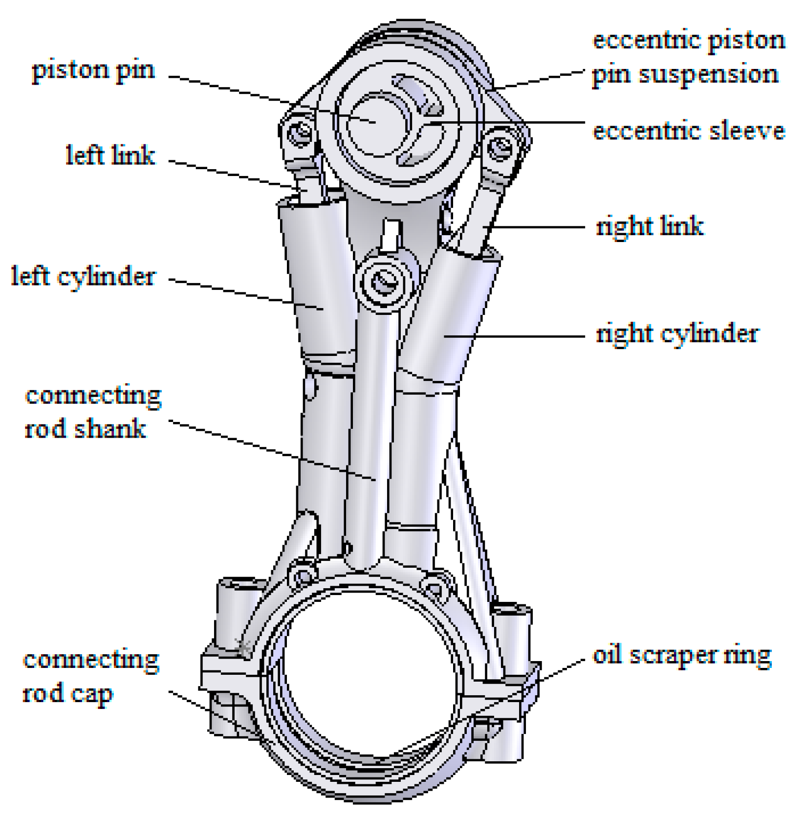
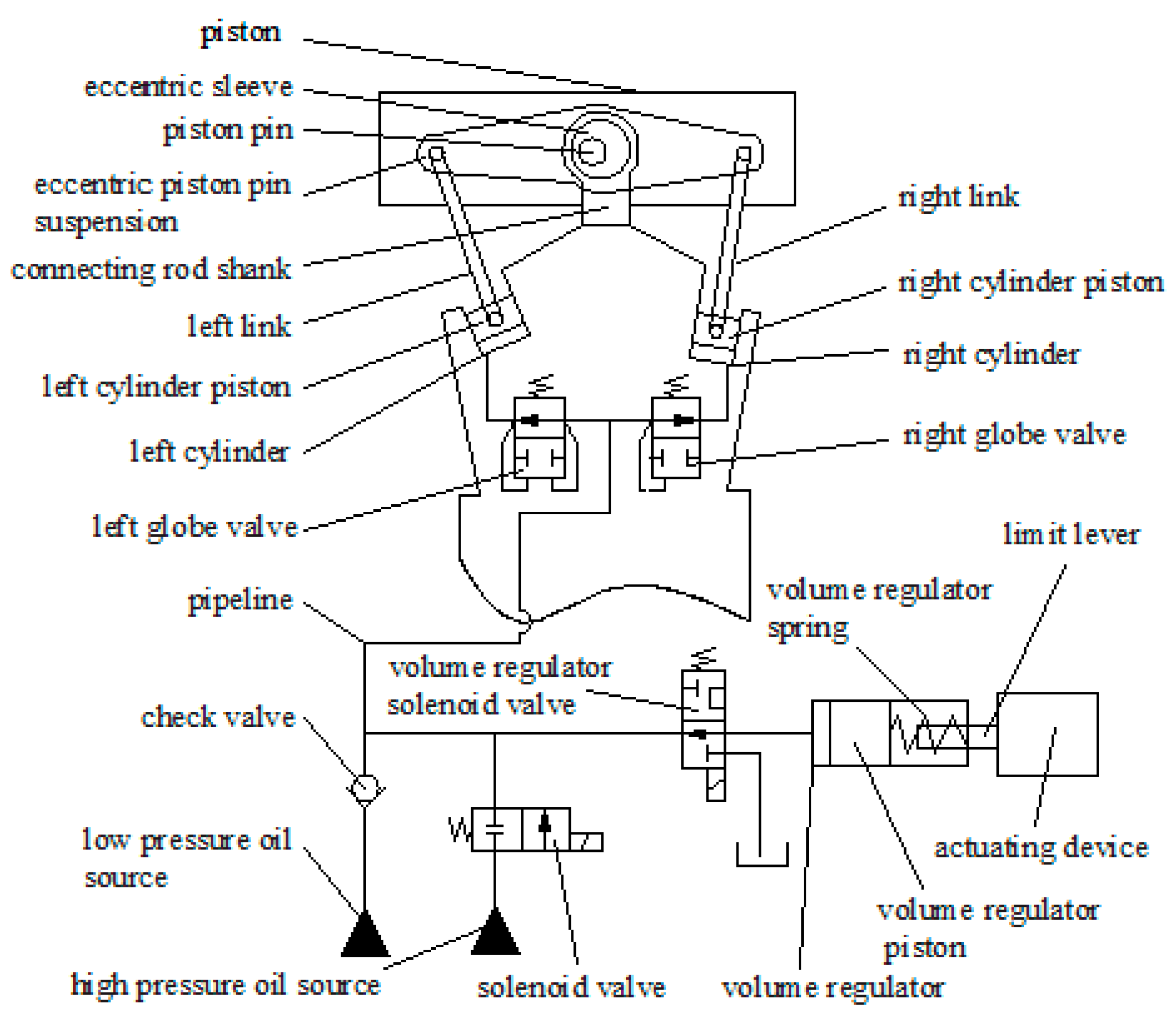
2.1. Structure of the VCR System

Figure 1 shows the structure of the connecting rod. The connecting rod is composed of eccentric piston pin suspension, a piston pin, a connecting rod shank, a connecting rod cap, a left link, a left cylinder, a right link, a right cylinder, a left globe valve, a right globe valve, and so on. The connecting rod small end is equipped with an eccentric sleeve which houses the piston pin. The cylindrical surface of the eccentric sleeve is matched with the hole of the connecting rod small end and thus the eccentric sleeve can rotate in the hole of the connecting rod small end. The eccentric piston pin suspension is in splined connection with eccentric sleeve. The eccentric piston pin suspension is connected to the left link of left cylinder and the right link of right cylinder respectively by means of articulated connection. Therefore, the eccentric sleeve would be rotated by changing the positions of the left cylinder and the right cylinder. Thereby the effective connecting rod length and thus the compression ratio can be varied by rotating the eccentric sleeve. Figure 2 is a schematic diagram of the hydraulic continuous VCR system. Figure 2 shows that the hydraulic system of the continuous VCR system is composed of a low-pressure oil source, high-pressure oil source, check valve, solenoid valve, left globe valve, right globe valve, left cylinder, right cylinder, volume regulator solenoid valve, volume regulator, and so on.

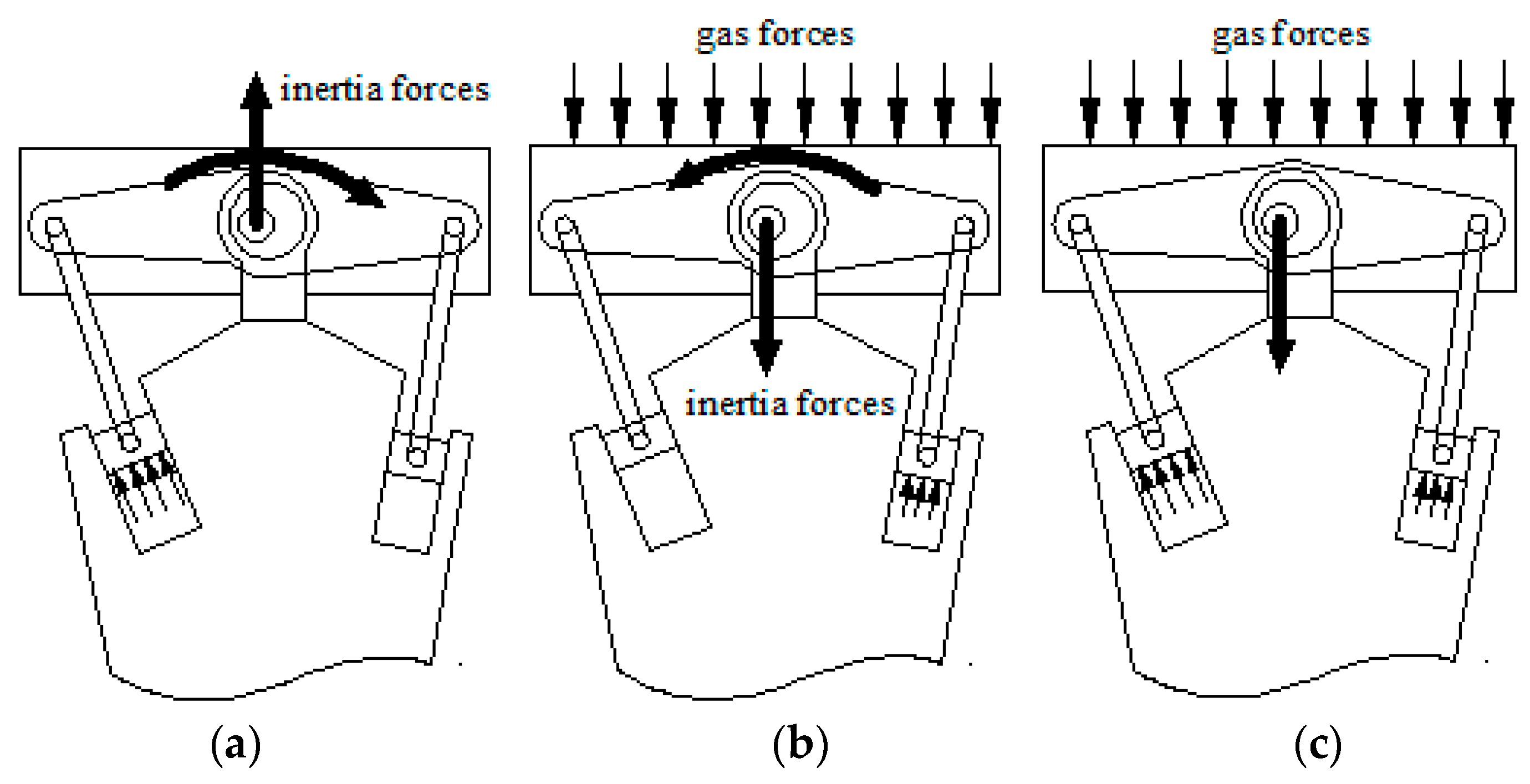
2.2. Working Principle of the VCR System

In the hydraulic continuous VCR system, compression ratio adjustment is realized by varying the position of the piston pin installed in the rotating eccentric sleeve that is controlled by the left cylinder and the right cylinder. As a result, the compression ratio adjustment completely relies on forces and moments related to movement of the piston for actuation and no external energy is necessary. The working principle of the hydraulic continuous VCR system is as shown below.
When it is necessary to adjust the compression ratio of the cylinder, the limit lever should be adjusted to a reasonable position by the actuating device, according to the speed and load of the engine. When the cylinder of the engine is running to the expansion stroke, the high-pressure oil circuit is disconnected by closing the solenoid valve of the high-pressure oil source. The system is supplied by the low-pressure oil source. At the same time, the solenoid valve of the volume regulator is turned on. The oil in the oil circuit connecting the volume regulator, the left globe valve, and the right globe valve flows into the volume regulator through the solenoid valve of the volume regulator, and the pressure of the connecting oil circuit then decreases. When the pressure of the connecting oil circuit is lower than the closing pressure of the right globe valve, the right globe valve is turned on. At the same time, due to the action of the high gas pressure on the surface of the engine piston, the oil pressure in the left cylinder is still very high. As a result, the left globe valve that is controlled by the pressure of the oil circuit is also closed. As the cylinder runs to the exhaust stroke, the gas pressure on the piston surface of the cylinder gradually decreases. When the engine runs to the later stage of the exhaust stroke and the early stage of the inlet stroke of the cylinder, the oil pressure of the left cylinder will be lower than that set by the left globe valve, and the left globe valve will be turned on. At this stage, the inertia force of the engine piston, piston pin, etc., which can move relative to the engine-connecting rod, will point in the upward direction shown in the figure. Under the combined action of the inertia force and the force of the oil pressure on the left piston, the center of the piston pin moves upward, which drives the eccentric piston pin suspension to rotate clockwise, as shown in Figure 3a. The clockwise rotation of eccentric piston pin suspension drives the left piston to move upward in the left cylinder through the left link, and the volume of the left cylinder gradually increases. On the contrary, the right piston moves downward in the right cylinder under the action of clockwise rotation of the eccentric piston pin suspension, so that the volume of the right cylinder will gradually decrease. Since the diameter of the left cylinder is larger than that of the right cylinder and the change of volume of the left cylinder is also greater than that of the right cylinder, all the oil flowing out of the right cylinder flows into the left cylinder. The same occurs for the left cylinder, so all the oil flowing out of the volume regulator flows into the left cylinder until the piston of the volume regulator returns to the front of the volume regulator by the spring force. While the pressure of the system is less than that of the low-pressure oil source, the low-pressure oil source supplies oil to the system through the check valve, and makes the system pressure the same as its oil pressure. As the right piston moves to the bottom of the right cylinder, the left piston reaches its highest position and stops moving. At the same time, the low-pressure oil source stops supplying oil to the system and the check valve is closed. A closing system with the largest volume is formed by the left cylinder, the right cylinder, the volume regulator, and their connecting circuits. The same maximum volume condition will be reached each time the compression ratio is adjusted.
When the cylinder runs to the later stage of the inlet stroke and the early stage of the compression stroke, the inertia force direction of the piston, piston pin, and other parts whose movements are relative to the engine piston becomes downward. Under the combined action of the inertia force and the force of oil pressure on the left piston and the right piston, the center of the piston pin moves upward, which drives the eccentric piston pin suspension to rotate counterclockwise, as shown in Figure 3b. The counterclockwise rotation of eccentric piston pin suspension drives the left piston to move downward in the left cylinder through the left link, and the volume of the left cylinder will gradually decrease. On the contrary, the right piston moves upward in the right cylinder under the action of the counterclockwise rotation of the eccentric piston pin suspension, so that the volume of the right cylinder will gradually increase. However, the volume variation of the left cylinder is larger than that of the right cylinder; that is to say, only a part of the oil flowing out of the left cylinder can flow into the right cylinder. Therefore, the oil pressure of the system increases gradually. When the system pressure is greater than the pre-tightening force of the volume regulator spring, the piston of the volume regulator is pushed into the regulating rod by the oil. The piston of the volume regulator stops moving after it makes contact with the limit lever, and the movement of the left piston and the right piston stops at the same time. The solenoid valve of the volume regulator is turned off. Then, medium in the left cylinder and the right cylinder becomes incompressible so that the eccentric piston pin suspension no longer rotates, as shown in Figure 3c. The oil in the volume regulator flows back to the tank through the solenoid valve of the volume regulator and the piston of the volume regulator returns to the front of the volume regulator by the spring force.
From above, the stroke of the volume regulator piston can be controlled by adjusting the position of the limit lever properly, according to the required compression ratio. This means that the oil volume flowing into the volume regulator cylinder can be controlled. The volume of oil is equal to the sum of the volumes of all hydraulic components in a closed hydraulic system. Therefore, when the cubic capacity of the volume regulator is determined, the volume of the left cylinder and the volume of the right cylinder are also determined because of their linkage and constant flow difference. Accordingly, the stop positions of the left piston and the right piston are determined, and the position of the eccentric piston pin suspension is also determined. Furthermore, the distance between the piston pin and the hole of the connecting rod end is determined too. The effective length of the connecting rod can be adjusted in this way, so the compression ratio of the engine is adjusted. As the cylinder compression stroke continues, the pressure of gas acting on the piston surface continues to rise, and the left piston will continue to move downward, which makes the system pressure rise rapidly. The left globe valve closes when the system pressure is greater than the set pressure of the left globe valve and this is maintained until the next compression ratio adjustment. The right globe valve is the same as the left globe valve. At the same time, the solenoid valve of the high-pressure oil source is turned on, which connects the high-pressure oil source and the connecting oil circuit. The supply of the high-pressure oil source ensures that the left globe valve and the right globe valve are always closed.
If the compression ratio needs to be adjusted again, the above process only needs to be repeated.

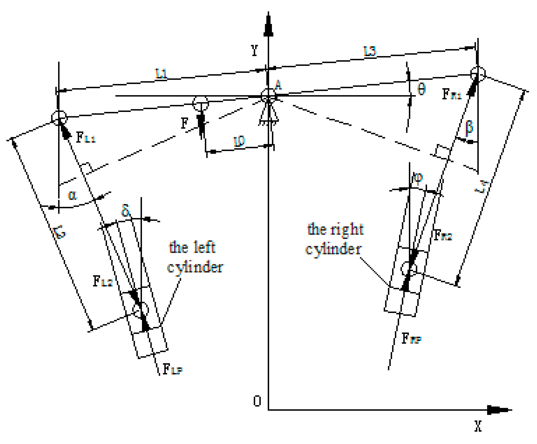
3. Mathematical Modeling

According to the working principle of VCR, the eccentric piston pin suspension rotates around the center of the eccentric sleeve. As shown in Figure 4, the eccentric piston pin suspension, the left cylinder, and the right cylinder form two crank slider mechanisms by using the engine-connecting rod as the reference for motion. L0 is the eccentric size, L1 is the left arm length of eccentric piston pin suspension, L2 is the left link length, L3 is the right arm length of eccentric piston pin suspension, L4 is the right link length, θ is the angular displacement of eccentric piston pin suspension, α is the angular displacement of the left link, β is the angular displacement of the right link, δ is the installation angle of the left cylinder, φ is the installation angle of the right cylinder, F is the force of the engine piston acting on the eccentric piston pin suspension, FL1 is the force of the left link acting on the eccentric piston pin suspension, FL2 is the force of the left link acting on the piston of left cylinder, FLP is the force of oil pressure on the piston of the left cylinder, FR1 is the force of the right link acting on the eccentric piston pin suspension, FR2 is the force of the right link acting on the piston of the right cylinder, and FRP is the force of oil pressure on the piston of the right cylinder.
According to the working principle of the VCR system and Figure 4, the system equations are derived one by one, as follows.
The piston displacement of the left cylinder s dL can be expressed as
s dL = ( L 1 cos θ L 2 sin α ) 2 + ( L 1 sin θ + L 2 cos α ) 2
The piston displacement of the right cylinder s dR is expressed as
s dR = ( L 3 cos θ L 4 sin β ) 2 + ( L 3 sin θ + L 4 cos β ) 2
The equilibrium equation of eccentric piston pin suspension can be expressed as
F × L 0 cos θ + F R 1 × L 3 cos ( β + θ ) F L 1 × L 2 cos ( α θ ) = J d 2 θ dt 2
where J is the moment of inertia of eccentric piston pin suspension.
The equilibrium equation of the left cylinder piston is expressed as
F L 2 sin ( α δ ) F LP m LP d 2 s dL dt 2 c ds dL dt = 0
where c is the damping coefficient, m LP is the mass of the left cylinder piston, δ is the installation angle of the left cylinder, F L 2 = F L 1 , F LP = π d L 2 4 p L , d L is the diameter of the left cylinder piston, and p L is the operating pressure of the left cylinder.
The equilibrium equation of the right cylinder piston is expressed as
F R 2 sin ( β φ ) F RP m RP d 2 s dR dt 2 c ds dR dt = 0
where c is the damping coefficient, m RP is the mass of the right cylinder piston, φ is the installation angle of the left cylinder, F R 2 = F R 1 , F R 2 = π d R 2 4 p R , d R is the diameter of the right cylinder piston, and p R is the operating pressure of the left cylinder.
The flow continuity equation in the left cylinder is as follows:
Q L = { π d L 2 4 ds dL dt β e ( V L 0 π d L 2 4 S dL ) d P L dt the   left   globe   valve   opened 0 the   left   globe   valve   closed
where β e is the elastic coefficient of the hydraulic medium and V L 0 is the initial volume of the left cylinder.
The flow continuity equation in the right cylinder is as follows:
Q R = { π d R 2 4 ds dR dt + β e ( V R 0 + π d R 2 4 S dR ) d P R dt the   right   globe   valve   opened 0 the   right   globe   valve   closed
where V R 0 is the initial volume of the right cylinder.
The flow continuity equation in the volume regulator is as follows:
Q R = { π d V 2 4 ds dV dt + β e ( V V 0 + π d V 2 4 S dV ) d P V dt the   solenoid   valve   opened 0 the   solenoid   valve   closed
where s dV is the piston displacement of the volume regulator, V V 0 is the initial volume of the volume regulator, d V is the diameter of the volume regulator piston, and p V is the operating pressure in the volume regulator.
The equilibrium equation of the volume regulator piston is as follows:
π d V 2 4 p V m V d 2 s dV dt 2 c ds dV dt F V 0 k V 0 s dV = 0
where F V 0 is pre-tightening force of volume regulator spring, and k V 0 is the stiffness of volume regulator spring.
The flow continuity equation of the check valve is as follows:
Q C = { A cd 2 × ( 0.25 p L ) ρ , p L < 0.25   and   the   left   globe   valve   opened 0 , p L > 0.25   or   the   left   globe   valve   closed
where A cd is the effective flow area of the check valve and ρ is the density of the hydraulic medium.
System flow balance equation:
According to the working principle of VCR, the system flow balance equation can be divided into two cases. The first case is when the resultant force is upwards, and the flow of the left cylinder is equal to the total of the flow of the right cylinder and the flow of check valve:
Q L = Q R + Q C
Another case is when the resultant force is downwards, and the flow of the left cylinder is equal to the total of the flow of the right cylinder and the flow of the volume regulator:
Q L = Q R + Q V

4. Simulation Model and Simulation Results

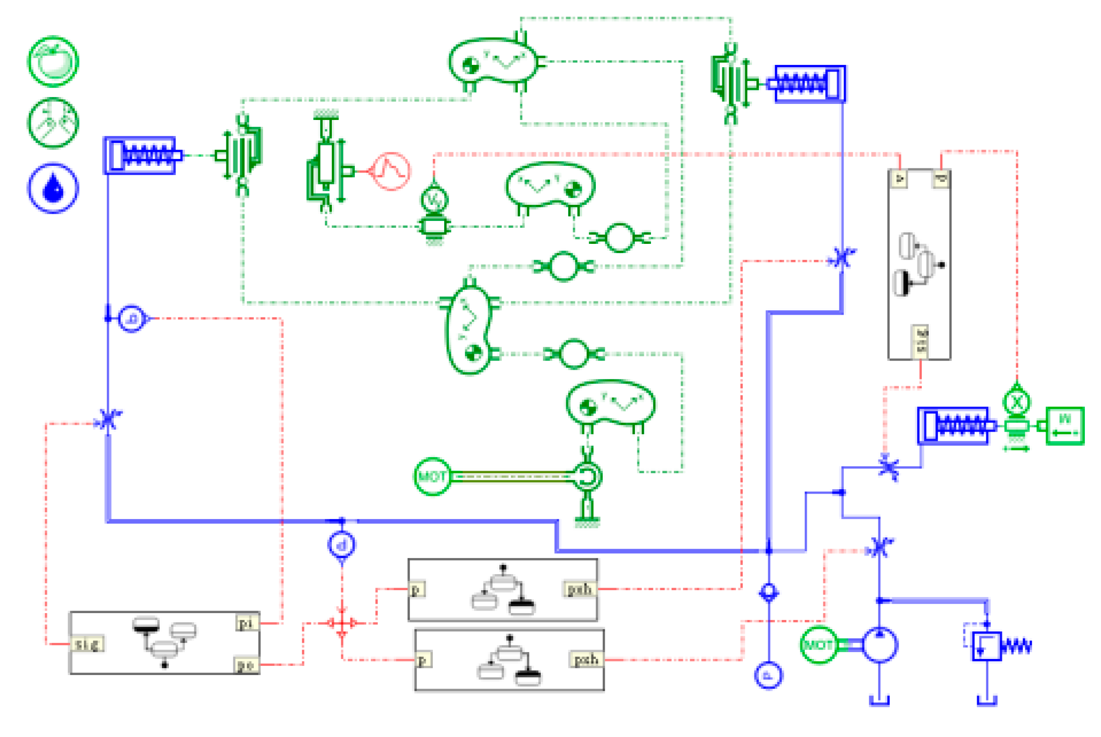
4.1. Simulation Model

Advanced Modeling Environment for performing Simulation of engineering system (AMESim) was selected as the simulation software. The simulation model was established by the AMESim software according to the working principle and construction of VCR. Figure 5 is the simulation model of VCR. The compressibility of hydraulic oil and pressure loss existing in the physical system are considered in the simulation model. The planar mechanical library of AMESim was used for the modeling of the mechanical structure of VCR. Additionally, the hydraulic library of AMESim was used for the modeling of the hydraulic system of VCR. In the simulation model, the variable hydraulic orifices are used to simulate the hydraulic valve, including the solenoid valve, left globe valve, right globe valve, and volume regulator globe valve, in the physical model. The switch of all variable hydraulic orifices is controlled by the signal of the sensors. The low-pressure oil source is simulated by a constant-pressure oil source. The high-pressure oil source is simulated by a subsystem that consists of a fixed displacement hydraulic pump, pressure relief valve, and so on. An electromotor is used to simulate the rotation of the engine driving the rotation of the crank axle. The motion between the cylinder and piston of the engine is simulated by a driven prismatic pair. Furthermore, the force of the engine piston is applied by the piecewise linear signal source. The parameter setting of the simulation model should refer to the physical system, and the simulation parameters are shown in Table 1.

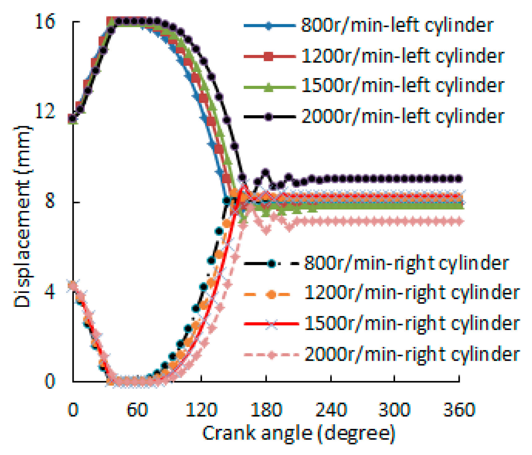
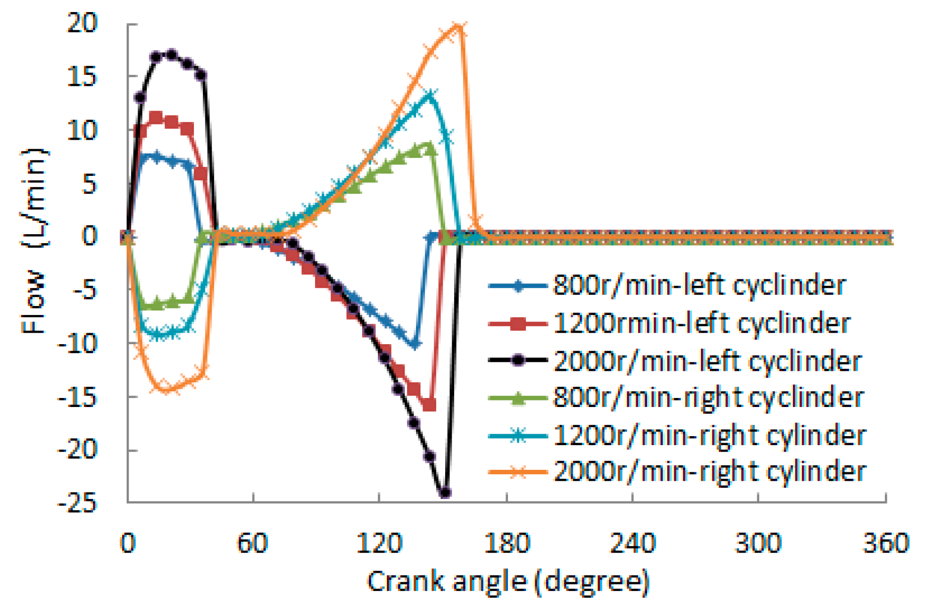
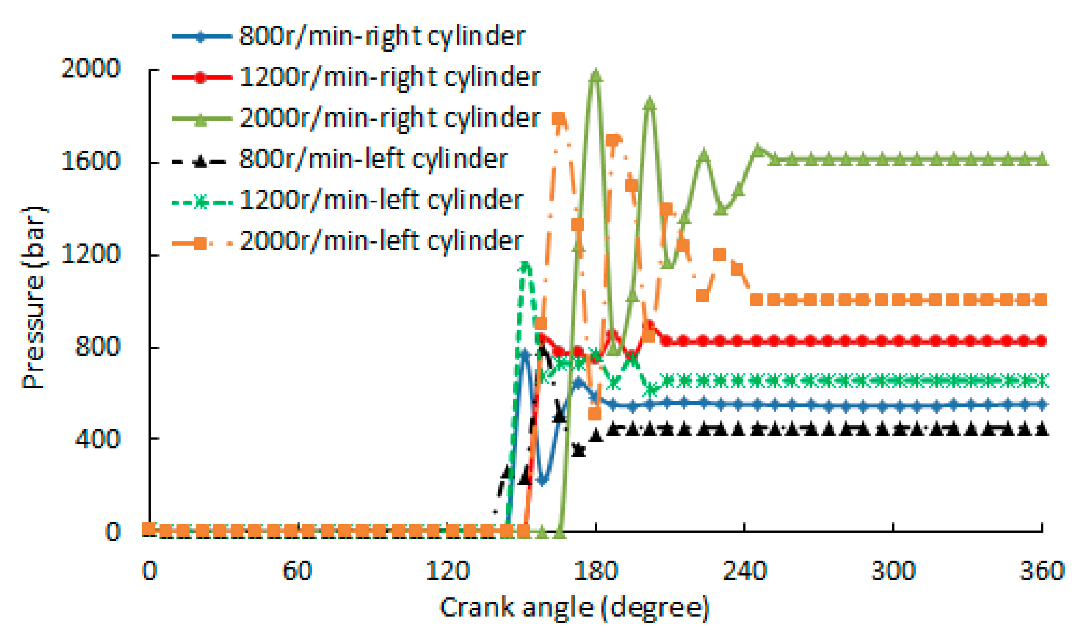
4.2. Simulation Results

In order to study the dynamic characteristics of the hydraulic system of VCR, the adjustment process of different engine speeds and different regulating quantities was simulated. According to the working principle and construction of VCR, the initial displacement of the left cylinder piston, the initial displacement of the right cylinder piston, and the initial displacement of the volume regulator piston were set to 11.7 mm, 4.3 mm, and 0 mm, respectively. The simulation results are shown below.
Figure 6 presents the simulation results of left cylinder piston displacement and right cylinder piston displacement at different engine speeds with the adjustment of 3 mm. From Figure 6, we know that the displacement of the left cylinder piston increases gradually to the stroke of the left cylinder, and then decreases gradually, in contrast to the left piston, where the displacement of the right piston first decreases to 0 and then increases gradually. It can also be seen that the greater the engine speed, the greater the crank angle required to complete the adjustment process. There is a fluctuation of piston displacement before the piston position is stable, and the fluctuation increases with the engine speed. There are the same adjustment effects of piston displacement at 800 r/min, 1200 r/min, and 1500 r/min. Once the piston position is determined, the compression ratio is also determined according to the structure of the VCR system. Therefore, 800 r/min, 1200 r/min, and 1500 r/min can have the same compression ratio at the same adjustment quantity. However, the piston displacement at 2000 r/min is greater than that at other engine speeds. In other words, when the engine speed is higher than a certain speed, i.e., 1500 r/min, the adjustment effect of the VCR system will be affected by the engine speed and it cannot obtain the same compression ratio as the lower engine speed. In order to ensure effective adjustment of the compression ratio, the VCR system must work under a certain engine speed, i.e., 1500 r/min. From Figure 6, we can also see that the adjustment of the piston position at the different engine speeds is completed before 180°, which enables the VCR system to achieve adjustment of the compression ratio in one engine duty cycle.
Figure 7 presents the simulation results of the left cylinder flow and right cylinder flow at the adjustment of 3 mm under different engine speeds. Figure 7 shows that both the inflow and outflow of the left cylinder are larger than those of the right cylinder at each engine speed, with the same adjustment. The figure also shows that the inflow of the left cylinder is greater than the outflow of the left cylinder at each engine speed, with the same adjustment, and the outflow of the right cylinder is smaller than the inflow of the right cylinder at each engine speed, with the same adjustment. This is due to the diameter of the left cylinder being larger than that of the right cylinder and the linkage between the two cylinders. It can be also seen that the flow increases with the engine speed at the same adjustment quantity. The higher the engine speed, the less time it takes for the engine to rotate the same angular displacement. However, the flowing volume caused by the same adjustment quantity is the same. Therefore, the higher the engine speed, the higher the flow.
The simulation results in Figure 8 show that the pressure drops from the initial pressure of the left cylinder and right cylinder to the same pressure as the system, and then gradually increases. When the system pressure reaches the closing pressure of the variable hydraulic orifices, the variable hydraulic orifices close. The pressure of the left cylinder and the pressure of the right cylinder rise sharply with fluctuation after the variable hydraulic orifices close. The simulation results indicate that the pressure fluctuation at a high engine speed is more severe than that at a low engine speed. We can also see that the cylinder pressure increases with the engine speed, and the maximum pressure of the left cylinder reaches 1800 bar at 2000 r/min, while the maximum pressure of the right cylinder is close to 2000 bar. It is necessary to take measures to reduce the pressure in the left cylinder and right cylinder to ensure the working reliability of the system.
Figure 9 presents the simulation results of left cylinder piston displacement and right cylinder piston displacement at 800 r/min, with different adjustment quantities. From the figure, we can see that the displacement of the left cylinder piston increases gradually to the stroke of the left cylinder, and then decreases gradually, and in contrast to the left cylinder piston, the displacement of the right cylinder piston first decreases to 0 and then increases gradually. All piston displacement curves are almost similar before the piston stops moving. The displacement of the left cylinder piston decreases with the increase of the displacement adjustment of the volume regulator piston. However, the displacement of the right cylinder piston increases with the increase of the displacement adjustment of the volume regulator piston. According to the structure of the VCR system, if the positions of the left cylinder piston and right cylinder piston are changed, the compression ratio of the engine will be changed. The adjustment of the piston position at the different adjustment quantities is completed before 180°. Therefore, the VCR system can achieve adjustment of the compression ratio in one engine duty cycle, which greatly ensures the reliable operation of the engine. In sum, the VCR system can change the compression ratio of the engine by adjusting the maximum displacement volume regulator piston.
The simulation results in Figure 10 and Figure 11 show the flow changes with the change of displacement adjustment of the volume regulator piston at 800 r/min. There are the same flows for the left cylinder, the right cylinder, and the check valve at different adjustment quantities before a 60° crank angle. However, the flow of the volume regulator is zero during this period. The flow of the left cylinder is equal to the sum of the flow of the right cylinder and the flow of the check valve before a 60° crank angle. As the adjustment quantity is increased, both the duration angle and the flow of the medium are increased when the crank angle is more than 60°. During the period, the flow of the check valve is zero and the flow of the left cylinder is equal to the sum of the flow of the right cylinder and the flow of the volume regulator. More hydraulic medium flows out of the left cylinder with the increase of adjustment quantity, which increases the flow of each cylinder and prolongs the flow time of the medium.
Figure 12 shows the simulation results of the pressure in the left cylinder and the right cylinder with different displacement adjustment of the volume regulator piston at 800 r/min. The pressure drops from the initial pressure of the left cylinder and right cylinder to the same pressure as the system. When the piston of the left cylinder moves downward, the system pressure rises gradually. The pressure fluctuation in the left cylinder is strengthened as the adjustment increases after the variable hydraulic orifices close. The pressure fluctuation of the right cylinder is opposite to that of the left cylinder. There is no regularity in the stable pressure of the left cylinder and the right cylinder. The stable pressure of 1 mm adjustment is smaller than that of 2 mm adjustment, but larger than that of 4 mm adjustment.
In summary, this novel hydraulic continuous VCR system can continuously adjust the compression ratio of the engine in one duty cycle of the engine, as long as the volume regulator is properly adjusted according to the engine speed.

5. Conclusions

Various approaches of VCR technology have been realized. However, up to now, no VCR engines have been found in series production. One reason for this might be the fact that most of the VCR solutions require comprehensive changes to existing engine architectures. A novel hydraulic continuous VCR system based on the principle of an adjustable hydraulic volume is introduced in this paper. The mathematical model of the novel VCR system, with an engine-connecting rod as the reference material, is established, which clearly states the working principle of the VCR system from the theory.
An AMESim simulation model of the novel VCR system was produced in this study. The dynamic characteristics of the hydraulic system of the VCR system were comprehensively studied using the simulation model. The simulation results show that the hydraulic system of the VCR system has good adjusting dynamic characteristics. The left cylinder piston and the right cylinder piston have their respective identical and defined positions at different engine speeds with the same adjustment quantity under the low engine speed. The final position of the left cylinder piston decreases as the adjustment increases, but the right cylinder piston reverses. Both the flow of the left cylinder and the flow of the right cylinder increase with the engine speed and adjustment quantity. The pressure fluctuation and stable pressure of the cylinders also increase with the engine speed after the variable hydraulic orifices close. However, there is no regularity in the stable pressure of the left cylinder and the right cylinder.
The simulation results also show that the novel hydraulic continuous VCR system can achieve continuous adjustment of the compression ratio of an engine.

Author Contributions

Conceptualization and methodology, J.C. and B.W.; investigation, J.C., B.W., D.L., and K.Y.; resources, J.C. and B.W.; writing—original draft preparation, J.C. and B.W.; writing—review and editing, J.C., B.W., D.L., and K.Y.; Funding acquisition, J.C.

Funding

This research was funded by the Foundation of Guizhou Educational Committee (KY [2017]106) and Guizhou University talent fund (no. 2015-50).

Acknowledgments

We gratefully acknowledge the support of Wang (Ziqin Wang), who helped guide this research.

Conflicts of Interest

The authors declare no conflicts of interest.

References

  1. Dhananjay, K.S.; Avinash, K.A. Combustion characteristics of a variable compression ratio laser-plasma ignited compressed natural gas engine. Fuel 2018, 214, 322–329. [Google Scholar]
  2. Feng, D.Q.; Wei, H.Q.; Pan, M.Z. Comparative study on combined effects of cooled EGR with intake boosting and variable compression ratios on combustion and emissions improvement in a SI engine. Appl. Therm. Eng. 2018, 131, 192–200. [Google Scholar] [CrossRef]
  3. Yang, S.; Lin, J.S. A theoretical study of the mechanism with variable compression ratio and expansion ratio. Mech. Based Des. Struct. Mach. 2018, 46, 267–284. [Google Scholar] [CrossRef]
  4. Hoeltgebaum, T.; Simoni, R.; Martins, D. Reconfigurability of engines: A kinematic approach to variable compression ratio engines. Mech. Mach. Theory 2016, 96, 308–322. [Google Scholar] [CrossRef]
  5. Westerloh, M.; Twenhövel, S.; Koehler, J.; Schumacher, W. Worldwide Electrical Energy Consumption of Various HVAC Systems in BEVs and Their Thermal Management and Assessment. SAE Tech. Pap. Ser. 2018. [Google Scholar] [CrossRef]
  6. Caio, H.R.; Janito, V.F. Kinematics of a variable stroke and compression ratio mechanism of an internal combustion engine. J. Braz. Soc. Mech. Sci. Eng. 2018, 40, 476–489. [Google Scholar]
  7. Jiang, S.; Smith, M.H. Geometric Parameter Design of a Multiple-Link Mechanism for Advantageous Compression Ratio and Displacement Characteristics. SAE Tech. Pap. Ser. 2014, 1. [Google Scholar] [CrossRef]
  8. Karsten, W.; Frank, G.; Jakob, A.; Mario, M.; Vitor, C.; Thompson, L. Experimental investigation of a variable compression ratio system applied to a gasoline passenger car engine. Energy Convers. Manag. 2019, 183, 753–763. [Google Scholar]
  9. Asthana, S.; Bansal, S.; Jaggi, S.; Kumar, N. A Comparative Study of Recent Advancements in the Field of Variable Compression Ratio Engine Technology. SAE Tech. Pap. Ser. 2016, 1. [Google Scholar] [CrossRef]
  10. Mane, P.; Pendovski, D.; Sonnen, S.; Uhlmann, A.; Henaux, D.; Blum, R.; Sharma, V. Coupled Dynamic Simulation of Two Stage Variable Compression Ratio (VCR) Connecting Rod Using Virtual Dynamics. SAE Int. J. Adv. Curr. Prac. Mobil. 2019, 1. [Google Scholar] [CrossRef]
  11. Shelby, M.H.; Leone, T.G.; Byrd, K.D.; Wong, F.K. Fuel Economy Potential of Variable Compression Ratio for Light Duty Vehicles. SAE Int. J. Engines 2017, 10, 817–831. [Google Scholar] [CrossRef]
  12. Kojima, S.; Kiga, S.; Moteki, K.; Takahashi, E.; Matsuoka, K. Development of a New 2L Gasoline VC-Turbo Engine with the World’s First Variable Compression Ratio Technology. SAE Tech. Pap. Ser. 2018. [Google Scholar] [CrossRef]
  13. Romero, C.A.; Castañeda, E.D.J.H. Developing Small Variable Compression Ratio Engines for Teaching Purposes in an Undergraduate Program. SAE Tech. Pap. Ser. 2019. [Google Scholar] [CrossRef]
  14. Shaik, A.; Moorthi, N.S.V.; Rudramoorthy, R. Variable compression ratio engine: A future power plant for automobiles—An overview. Proc. Inst. Mech. Eng. Part D J. Automob. Eng. 2007, 221, 1159–1168. [Google Scholar] [CrossRef]
  15. Wittek, K.; Geiger, F.; Andert, J.; Martins, M.; Oliveira, M. An Overview of VCR Technology and Its Effects on a Turbocharged DI Engine Fueled with Ethanol and Gasoline. SAE Tech. Pap. Ser. 2017. [Google Scholar] [CrossRef]
  16. Shi, H.; Al Mudraa, S.; Johansson, B. Variable Compression Ratio (VCR) Piston—Design Study. SAE Tech. Pap. Ser. 2019. [Google Scholar] [CrossRef]
  17. Hiyoshi, R.; Aoyama, S.; Takemura, S.; Ushijima, K.; Sugiyama, T. A Study of a Multiple-link Variable Compression Ratio System for Improving Engine Performance. SAE Tech. Pap. Ser. 2006, 1. [Google Scholar] [CrossRef]
  18. Kadota, M.; Ishikawa, S.; Yamamoto, K.; Kato, M.; Kawajiri, S. Advanced Control System of Variable Compression Ratio (VCR) Engine with Dual Piston Mechanism. SAE Int. J. Engines 2009, 2, 1009–1018. [Google Scholar] [CrossRef]
  19. Kleeberg, H.; Tomazic, D.; Dohmen, J.; Wittek, K.; Balazs, A. Increasing Efficiency in Gasoline Powertrains with a Two-Stage Variable Compression Ratio (VCR) System. SAE Tech. Pap. Ser. 2013, 1. [Google Scholar] [CrossRef]
  20. Wolfgang, S.; Sorger, H.; Loesch, S.; Unzeitig, W.; Huettner, T.; Fuerhapter, A. The 2-Step VCR Conrod System—Modular System for High Efficiency and Reduced CO2. SAE Tech. Pap. Ser. 2017, 1. [Google Scholar] [CrossRef]
Figure 1. Structure of the connecting rod.
Applsci 09 04484 g001
Figure 2. Schematic diagram of the hydraulic continuous variable compression ratio (VCR) system.
Applsci 09 04484 g002
Figure 3. Schematic diagram of the adjustment process. (a) First stage of adjustment; (b) second stage of adjustment; (c) adjustment completion.
Applsci 09 04484 g003
Figure 4. Schematic diagram of force.
Applsci 09 04484 g004
Figure 5. Advanced Modeling Environment for performing Simulation of engineering system AMESim simulation model of variable compression ratio (VCR) system.
Applsci 09 04484 g005
Figure 6. Displacement of the cylinder piston at different engine speeds with the same adjustment quantity.
Applsci 09 04484 g006
Figure 7. Flow of cylinders at different engine speeds with the same adjustment quantity.
Applsci 09 04484 g007
Figure 8. Pressure of the left cylinder at different engine speeds with the same adjustment quantity.
Applsci 09 04484 g008
Figure 9. Displacement of the cylinder piston at 800 r/min with different adjustment quantities.
Applsci 09 04484 g009
Figure 10. Flow of 1 mm adjustment at 800 r/min.
Applsci 09 04484 g010
Figure 11. Flow of 4 mm adjustment at 800 r/min.
Applsci 09 04484 g011
Figure 12. Pressure of the cylinders at 800 r/min with different adjustment quantities.
Applsci 09 04484 g012
Table 1. Simulation parameters.
ItemParameter
Diameter of left cylinder piston (mm)15.4
Diameter of right cylinder piston (mm)13.8
Diameter of volume regulator piston (mm)10
Diameter of volume regulator rod (mm)5
Diameter of pipeline (mm)6
Stroke of left cylinder (mm)16
Stroke of right cylinder (mm)16
Initial displacement of left cylinder piston (mm)11.7
Initial displacement of right cylinder piston (mm)4.3
Initial displacement of volume regulator piston (mm)0
Initial pressure of right cylinder (bar)10
Initial pressure of left cylinder (bar)10
Initial pressure of volume regulator (bar)0
Initial pressure of pipeline (bar)2.5
Density of hydraulic medium (kg/mm3)850 × 10−9
Effective flow area of check valve (mm2)10
Maximum flow coefficient 0.7
Pre-tightening force of volume regulator spring (N)35
Stiffness of volume regulator spring (N/mm)1000
Hydraulic oil elastic modulus (bar/mm2)7
Mass of crank axle (kg)2
Mass of engine connecting rod (kg)0.4
Mass of eccentric piston pin suspension (kg)0.07
Length of left arm of eccentric piston pin suspension (mm)26
Length of right arm of eccentric piston pin suspension (mm)26
Length of pipeline (m)0.3
Eccentric size (mm)4
Pressure of low pressure oil source (bar)2.5

