Article

The Performance Assessment of a Precast, Panel-Segmented Arch Bridge with Outriggers

1
Civil Engineering, Gyeongnam National University of Science and Technology, Jinju 52725, Korea
2
R&D Team, Tekhan Inc., Seongnam 13524, Korea
3
Department of Ocean Civil Engineering, Chonnam National University, Yeosu 59626, Korea
*
Author to whom correspondence should be addressed.
Appl. Sci. 2019, 9(21), 4646; https://doi.org/10.3390/app9214646
Submission received: 28 September 2019 / Revised: 27 October 2019 / Accepted: 28 October 2019 / Published: 1 November 2019
(This article belongs to the Section Civil Engineering)

Abstract

:
Stone arch bridges, which are globally implemented, are advantageous with respect to material strength and durability. To minimize environmental damage from arch bridges, a structurally stable scheme that can resist variable external loads is required. This paper proposes a segmented precast arch bridge with outriggers to resist both the tensile force applied on the precast panels and the compressive force during construction and use. To assess the structural behavior and safety of the proposed arch bridge, a three-dimensional (3D) nonlinear structural analysis was conducted, considering the construction step and rise ratio of the arch bridge. The structural analysis of the proposed arch bridge revealed that its maximum horizontal and vertical displacements occurred at the support of the precast panel and the arch crown in a self-weight state. However, because of the compressive resistance characteristics of the outriggers connected to the precast panels, the structure demonstrated an effective performance in the self-weight state. With an increase in the construction steps, and the final completion of proposed arch bridge via installation of the precast arch segments and earthwork for the precast arch bridge with outriggers, the deformation of the arch members was mitigated, and the relative difference between the stress distributions of the members reduced. Hence, the arch bridge achieved structural stability. Based on the thrust line analysis results of the arch bridge with respect to the construction step using 3D structural analysis results, the thrust line was formed outside the precast panel at the arch crown and support, so was attributed to the behavior of the arch bridge in a self-weight state. The thrust line was found to act within the precast panel depending on the construction step. Analysis results confirmed that the behavior of the precast panel arch bridge with the proposed outrigger was stable and structurally effective.

1. Introduction

Stone arch bridges have an extensive history, with various advantages with respect to material strength and durability. Hence, they have been used in numerous European countries, including the United Kingdom (UK), in a variety of forms [1,2]. Researchers recently investigated the development of various types of precast concrete and steel arch technologies. Accelerating bridge construction while also minimizing environmental damage incurred during bridge construction worldwide, was taken into account in Korea, where various precast arch bridges based on existing stone arch technology have been proposed. Moreover, the scope of application expands in accordance with the structural, mechanical and aesthetic advantages of arches. In general, the structural stability of stone arch bridges, which consist of materials with high compressive strengths, depend on the arch structural shapes (rise, ratio, etc.), rather than the material limitations [3]. Additionally, stone arch bridges resist external loads by the compressive strength of the stone and the frictional force on the contact surface generated from the arch members [4]. In the case of an underground arch or a precast arch structure, the moment caused by an external load acts as a compressive force on the arch section, such that the joints between the arch panels are in a fully compressed state [5,6,7]. For an arch structure, the thrust line is expressed based on the external force and the internal resistance, and the stability is evaluated depending on whether the thrust line exists in the central kern. In the case of a stone arch bridge, the central kern is a third of the section. If the thrust line significantly deviates from the central kern and either the extrados or intrados is subject to an excessive compressive stress, the structural system may reach its limit [8,9]. Additionally, the arch consists of a structure in which the centerline of the compressive force passes through the inside of the arch section because of the constraint effect of the backfill soil, even if a variable load is applied. However, when constructing the arch structure, although the axial force due to the self-weight of the arch structure is small, an uneven load is generated during the actual construction process, resulting in a moment. A typical countermeasure for this involves the support of the precast masonry arch structures separated by block units with temporary materials such as strut, which are kept until the filling is completed. However, this method requires an increased construction period and increased cost because of the temporary construction. Furthermore, although a method that involves the connection of the blocks and their collective installation can be considered, blocks with high thicknesses should be used, to prevent the thrust line from crossing the boundaries of the blocks during construction [10]. Consequently, the self-weight of the arch structure increases, resulting in issues such as increased material costs and lifting burden attributed to the increased weight. Another method involves the fabrication of the entire arch structure (or half of it) using integrated, precast concrete members rather than segmented concrete blocks. In this method, the structure is assembled on-site without the requirement of temporary materials, and the members can resist bending caused during construction. However, these precast concrete members require a minimal concrete thickness to resist bending; the use of reinforcement bars is excessive. Due to constraints on their sizes and shapes, fabrication and transport may not be efficient [11,12]. Moreover, arch bridges can be implemented by the application of rise ratios depending on the objective and the system [13,14]. With respect to underground arch structures, the application of such rise ratios can be considered as a system that converts the moment caused by the self-weight due to the upper soil mass into the compressive force in the underground arch structure. Thus, the behavior of the arch structure may be assessed differently with respect to an increase in the span of an arch structure of the same height.
In this study, the advantages and behaviors of existing precast and stone arch bridges were analyzed. From this analysis, an arch bridge connected by precast concrete panels, with outriggers that can supplement these advantages, is proposed in this paper. The proposed arch bridge allows for the assembly to be collectively lifted and installed; thus, minimizing the on-site construction time. In the proposed arch bridge, the outriggers, which are connected to a plurality of panels, enable ductile behavior using steel materials. The structure was composed with the aims of having the minimum bending stiffness required during use, and for the precast panel members to resist the compressive force using the arch characteristics, in which the structural moment generated by backfill soil and fill during construction and use (and other live loads) is converted to a compressive force. To verify the behavior of the proposed precast arch bridge and assess its stability under load, a three-dimensional (3D), nonlinear structural analysis was conducted to examine the stress and changes in displacement with respect to the rise ratio. With the analysis results, the structural behavior of the proposed precast, panel-segmented arch bridge with an outrigger was compared to others, and its structural safety and stability were explained. The aim of this study was to assess the behavioral characteristics and structural safety of constrained bridges, and from that, to propose a novel arch bridge type. In doing so, the applicability of the proposed bridge under specific span lengths and boundary conditions was evaluated.

2. Overview of the Proposed Arch Bridge System

The proposed precast, panel-segmented arch bridge with outriggers consists of precast panel-segment members, which are subject to compressive force, in addition to continuous rib-type outriggers, which resist tensile force. As shown in Figure 1, the precast, concrete segment panel with a relatively narrow and thin section has a circular shape at its end to transmit the compressive force through the contact between the precast panel and the panel. Each precast concrete-segment panel is connected with a steel V-strip. Precast concrete-segment panels connected by V-strips are integrated with the outrigger of the plate steel rib in the proposed segmented, precast arch bridge with an outrigger. Moreover, the arch bridge is prefabricated and assembled on-site; the assembled members can be collectively lifted and installed through the connecting rib of the outrigger. As opposed to various existing arch structures, for the proposed arch bridge system, temporary structures do not require on-site installation. The cross-section was constructed to bear the minimum bending stiffness required during use and to resist the bending moment generated during construction. This induces ductile behavior and maximizes the structural utilization of the backfill soil. Furthermore, the arch bridge allows for the thicknesses of the precast members to be rather low in accordance with the minimum cross-sectional area required to resist the compressive force during use. Thus, the light weight of the arch members can improve construction and reduce construction costs.
Given that the proposed arch bridge has a relatively flexible structure, passive earth pressure is applied in the direction that reduces the changes in the thrust line. Additionally, at the position wherein internal displacement occurs, the active earth pressure acts in the direction that decreases the earth pressure. Figure 2 presents a comparison of the thrust line of the proposed precast, panel-segmented arch bridge with outriggers and that of an existing three-hinged, precast arch bridge under self-weight; Figure 3 presents a comparison of the thrust lines under self-weight and earth pressure (construction conditions); Figure 4 presents a comparison of the thrust lines under self-weight and earth pressure (after construction); Figure 5 presents a comparison of the thrust lines under self-weight, earth pressure and additional load after completion (during use). As shown in Figure 2 and Figure 5, most of the thrust lines for each arch bridge are due to self-weight; those due to self-weight and earth pressure after construction were within the members. However, as shown in Figure 3, with lower side earth pressure under self-weight and construction conditions, the thrust line of the proposed precast, panel-segmented arch bridge with outriggers exceeded the boundaries of the arch bridge concrete panels. However, because of the tensile resistance of the externally-installed outriggers, forces that may occur during construction are resisted. As shown in Figure 5, the thrust line of the arch bridge may cross the boundaries of the arch concrete under the conditions of self-weight after construction, earth pressure and additional load (changes in earth pressure due to structural deformation), although the external load is resisted because of the tensile resistance of the externally-installed outriggers of the proposed scheme; this scheme is a system wherein the precast panels and outriggers resist compressive and tensile forces, respectively. Hence, under the load conditions during construction (Figure 2, Figure 3, Figure 4 and Figure 5) and the one-sided earth pressure (Figure 6), an efficient cross-section can be implemented based on the flexible behavior of the outriggers and precast panels.

3. Performance Assessment of the Proposed Arch Bridge System

3.1. Specifications of Target Structure

To compare the structural behavior of the proposed arch bridge, the precast panels and outriggers that compose the bridge must be considered; thus, the specifications of the precast panels and outriggers of the arch bridge were determined. The thickness and end details of the precast panels considered in this study can be applied to an arch bridge with a lengthwise span of 15 m; in this study, bridges with lengthwise spans of 6–8 m and heights of up to 3 m were reviewed, which is suitable for bridges that are elevated above ecological corridors or small and medium rivers.
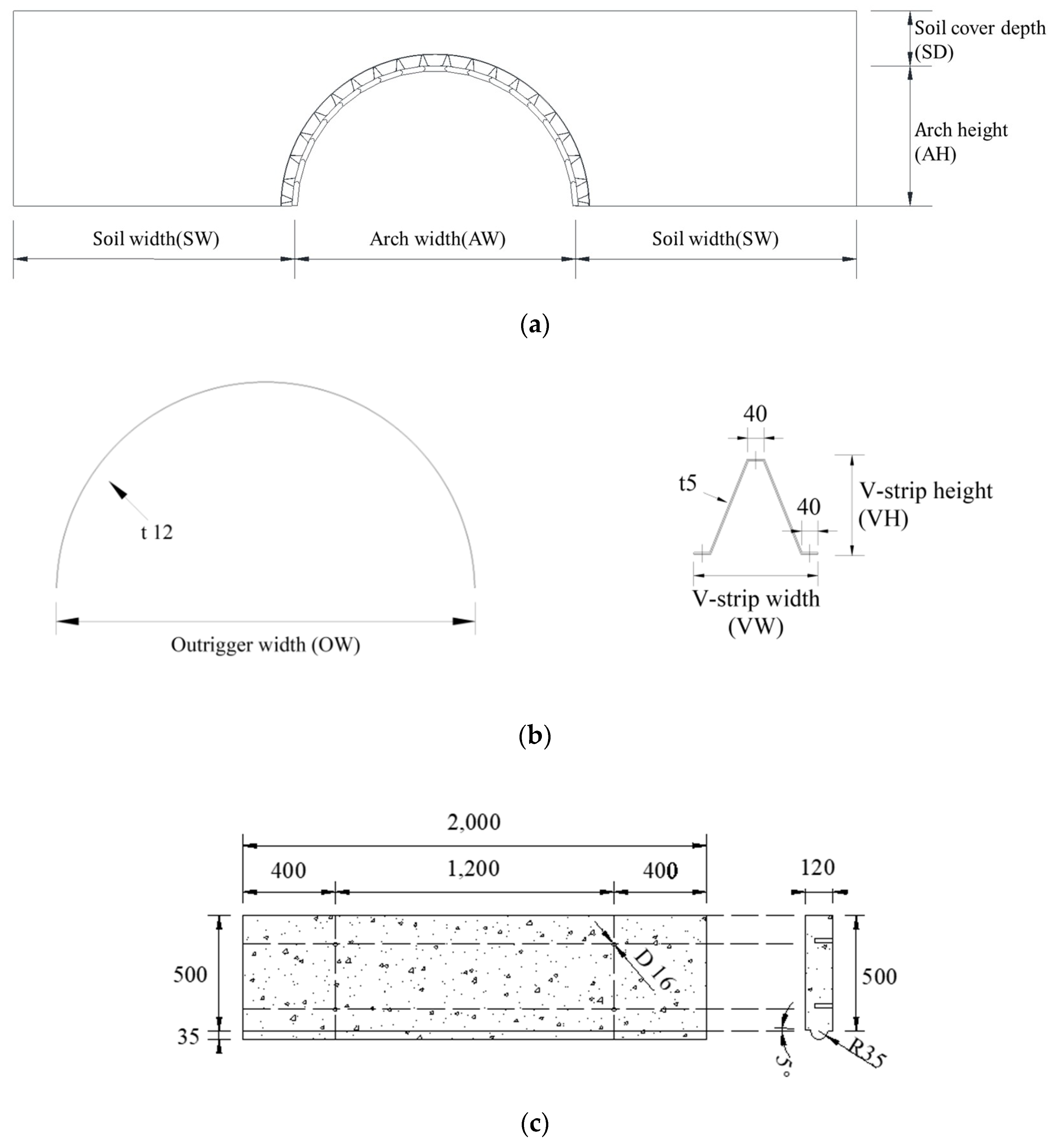
The thickness and width of the outriggers and V-strips of the target bridges were first determined for the structural analysis based on the values required to construct an arch with a maximum span of 15 m (rise ratio of 0.5). With respect to the fabrication and construction feasibility of the precast panel (Figure 7c), its specifications were determined as follows: length = 2,000 mm; thickness = 120 mm; width = 500 mm; diameter of circular connection = 70 mm. The thicknesses of the outriggers and V-strips, which were made from steel, were set as 12 mm and 5 mm, respectively (Figure 7b). For the precast panel members of the bridge, the connection interface was implemented as a circle that acts as a hinge between the precast panels.
In this study, the width and height of the outriggers and V-strips were changed according to the rise ratio, to account for the changes in the rise ratio with respect to the arch shape. To account for the loads during and after construction, backfill soil was applied as a load at each construction step. Additionally, similar to the actual structural system, the condition that prevents the occurrence of deformation at the outer-end of the backfill soil according to the behavior of the proposed arch bridge must be applied; to do so, the same width specification of the outrigger with the maximum width in the proposed arch bridge was used. In this study, rise ratios of approximately 0.5, 0.45 and 0.4 were applied according to the span. Table 1 summarizes the specifications of the target arch bridge members used in this study.
The soil cover depth applied as the load condition of the target bridge was calculated using the minimum soil cover depth Equations (1)–(3), as presented in the Canadian Highway Bridge Design Code [15]. Moreover, the largest value was used as the minimum soil cover depth value. In this study, a factor of 0.5 was applied to the vertical height based on the model with a height of 6 m, which is similar to a semicircle. For the arch bridge with a span of 6 m, the values calculated for the minimum soil cover depths were 600 mm, 1,000 mm and 400 mm using Equations (1)–(3), respectively.
Because of the structural characteristics of the proposed arch bridge, the bending moment generated during construction and the compressive force generated during use are resisted by the precast panels and outriggers. With an increase in the height of the soil mass loaded onto the structure, the stability of the arch structure was found to increase because of the introduction of the compressive force. Thus, in this study the height of the soil mass was set as 1,200 mm to confirm the effect of the soil mass. Although the minimum soil cover depth was found to change in accordance with an increase in the span, the same soil cover depth was applied to arch bridges with spans of 7 m and 8 m, to confirm the relative effect of the soil mass. As described above, the length of the backfill soil should be set in consideration of the ground boundary condition as continuous, which is similar to the actual structural system. Therefore, in this study the longitudinal length of the backfill soil was set as equal to the distance between the ends of each arch bridge outrigger (Figure 7a and Table 1).
0.6   m ,
S 6 ( D h D υ ) 1 2 ,
0.4 ( D h D υ ) 1 2 ,
where D h is the horizontal diameter, D v is the vertical diameter and S is the span.

3.2. Three-Dimensional Structural Analysis Modeling

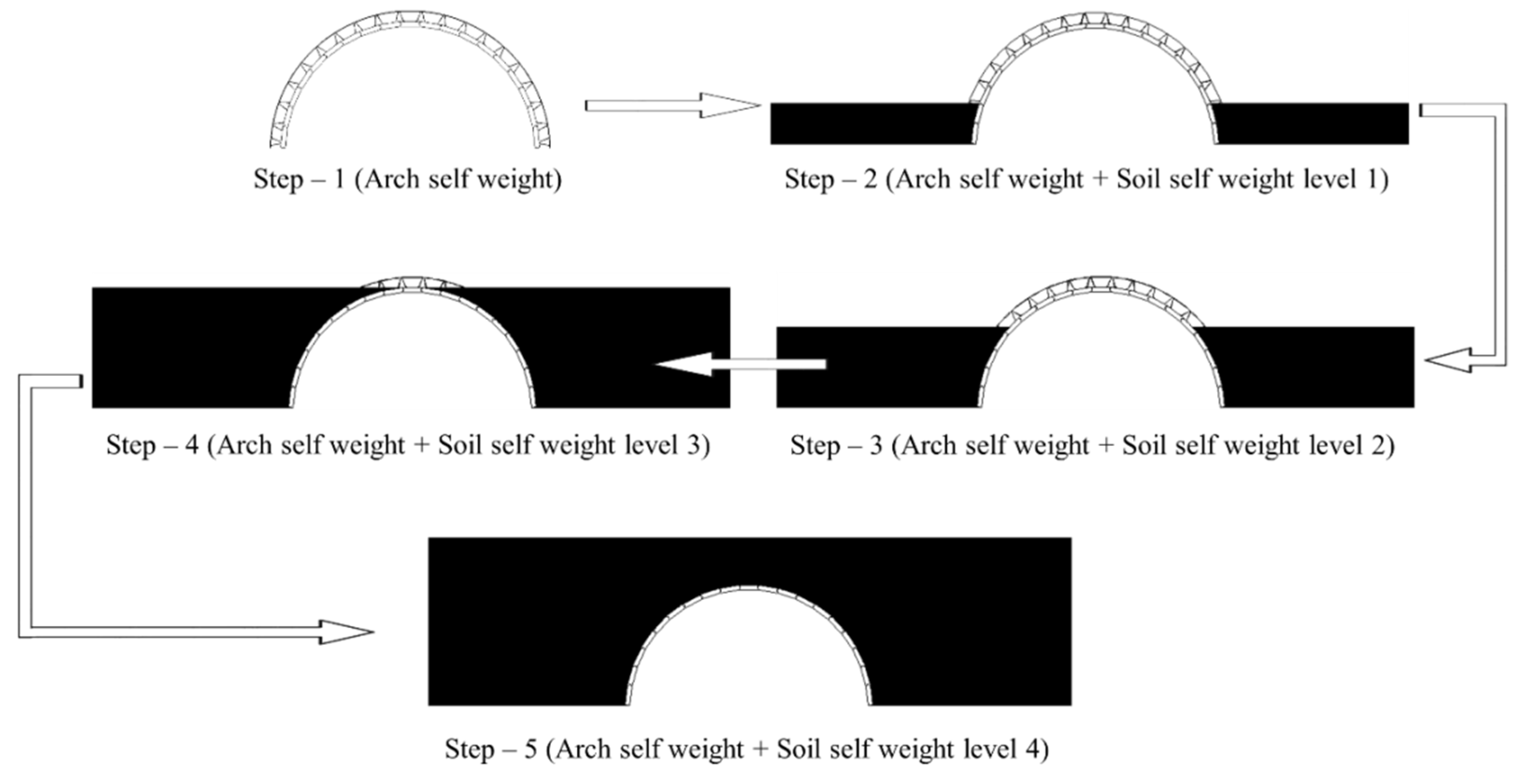
A 3D nonlinear structural analysis was conducted to analyze the behavior of the proposed precast, panel-segmented arch bridges with outriggers. To confirm the behavior at each construction step, five conditions were simulated (Figure 8). As can be seen from Figure 8, Step 1 represents the bridge in a self-weight state, Steps 2–4 represent the bridge upon application of the load at 1/3 of the height of the arch bridge and Step 5 represents the bridge upon the application of the load due to upper soil mass.
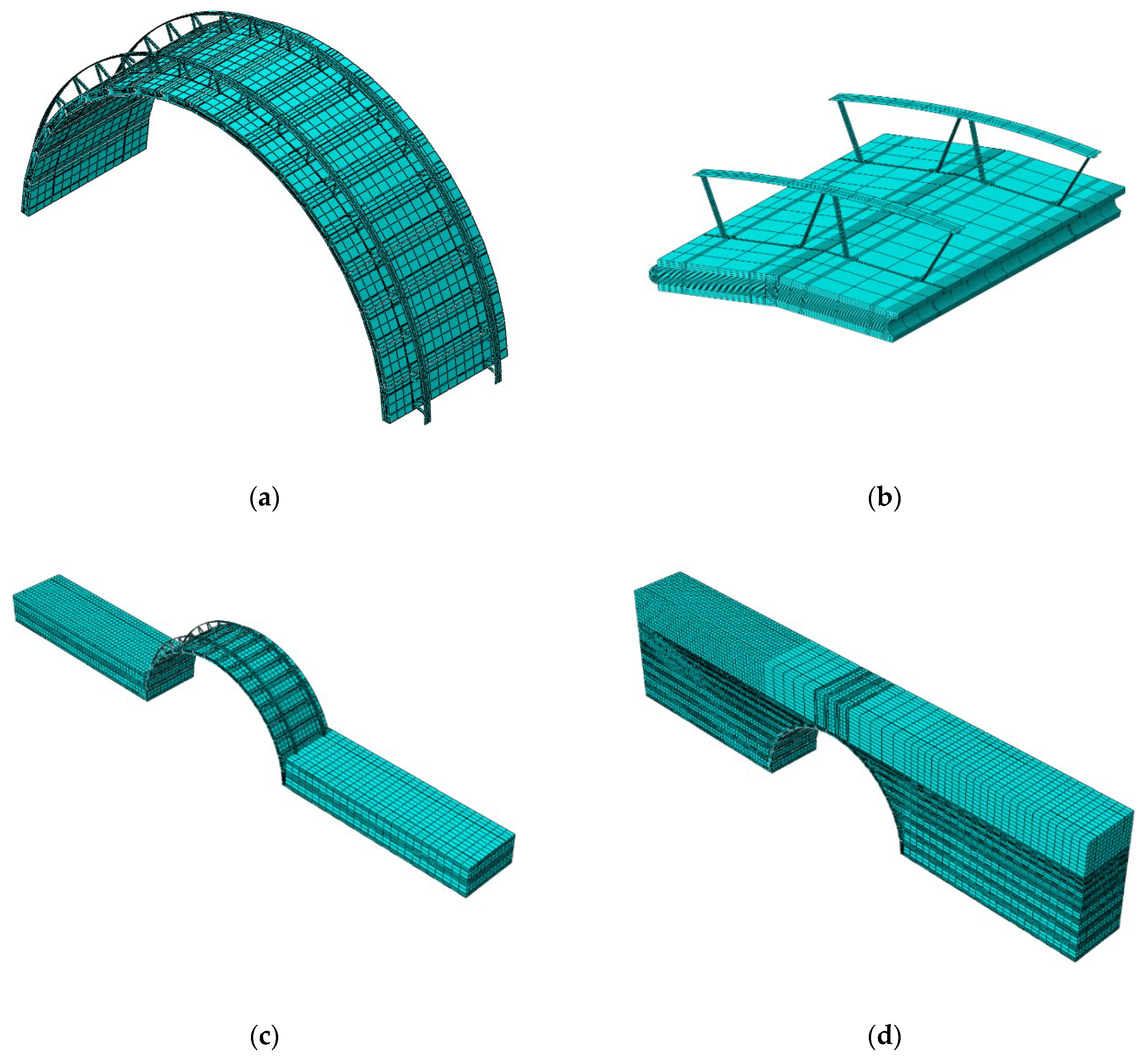
In this study, ABAQUS 6.14, a general-purpose finite element analysis program, was used to conduct non-linear 3D modeling and structural analysis of the target arch bridges [16]. In the model of the bridge with a span of 6 m, the precast panel members were free to rotate by approximately 9° to create an arch shape; 8° in the structural analysis of the model with a span of 7 m; and 7° in the structural analysis of the model with a span of 8 m. Figure 9a presents the 3D structural analysis model with a span of 6 m; Figure 9b presents the connection part between the precast arch panels of the proposed arch bridge. To demonstrate the loading effects of the bridges at each construction step, the soil mass was modeled as a 3D element, as shown in Figure 9c,d. Figure 9c presents the model of the Step 2 loading condition shown in Figure 8; Figure 9d presents the completed system model.

3.2.1. Material Properties of Structural Analysis Model

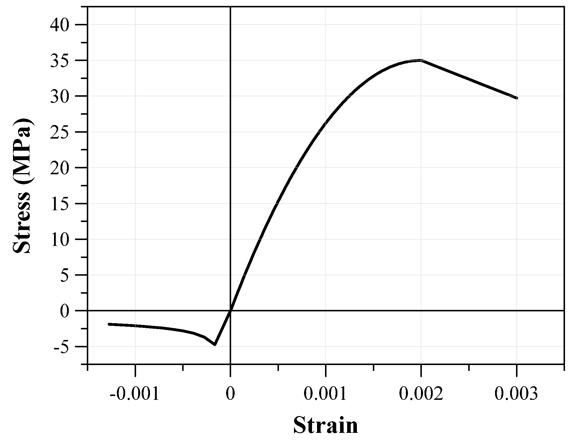
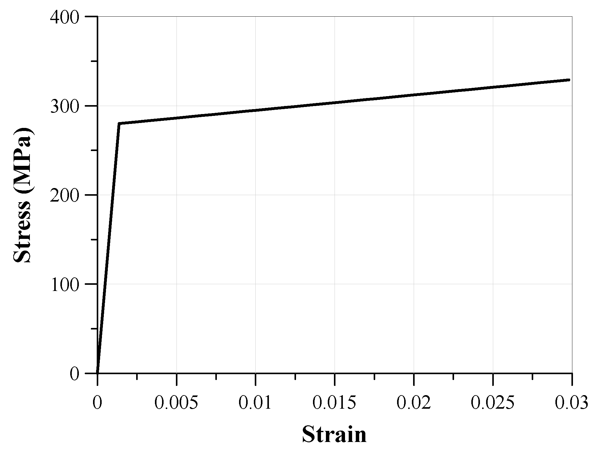
Three-dimensional models were created for the precast panels and backfill soils of the member elements of the proposed arch bridge using the eight-node solid element, and the shell element for the outriggers and V-strips [16]. The equation by Hognestad was applied to determine the stress–strain relationship [17]. Additionally, the compressive strength (fcu) with respect to the strain ε0 and ultimate strain εcu were set as 0.002 and 0.003, respectively. The standard design compressive strength was 35 MPa and the tensile strength was 4.7 MPa (or 13.5%). The elastic modulus of the precast panel was 28,825.3 MPa; the linear elastic section was assumed to reach 30% of the compressive strength of 35 MPa. Table 2 presents the properties of the precast material. Figure 10 presents the stress–strain relationship of the precast panel with a compressive strength of 35 MPa. The outriggers and V-strips were made from steel with a material yield strength of 280 MPa and a maximum tensile strength of 450 MPa. Moreover, an elastic modulus of 205,000 MPa and unit mass of 7,850 kg/m3 were applied. Figure 11 presents the stress–strain relationships of the outriggers and V-strips. Under the assumption that the backfill soil is generally used as sandy soil, a unit weight of 1.94 t/m3 was used, as shown in Table 2. This was assumed to be an elastic plastic material according to Mohr–Coulomb theory. An internal friction angle of 30° was used; 0.33 was used as Poisson’s ratio.

3.2.2. Structural Analysis Model’s Contact and Boundary Conditions

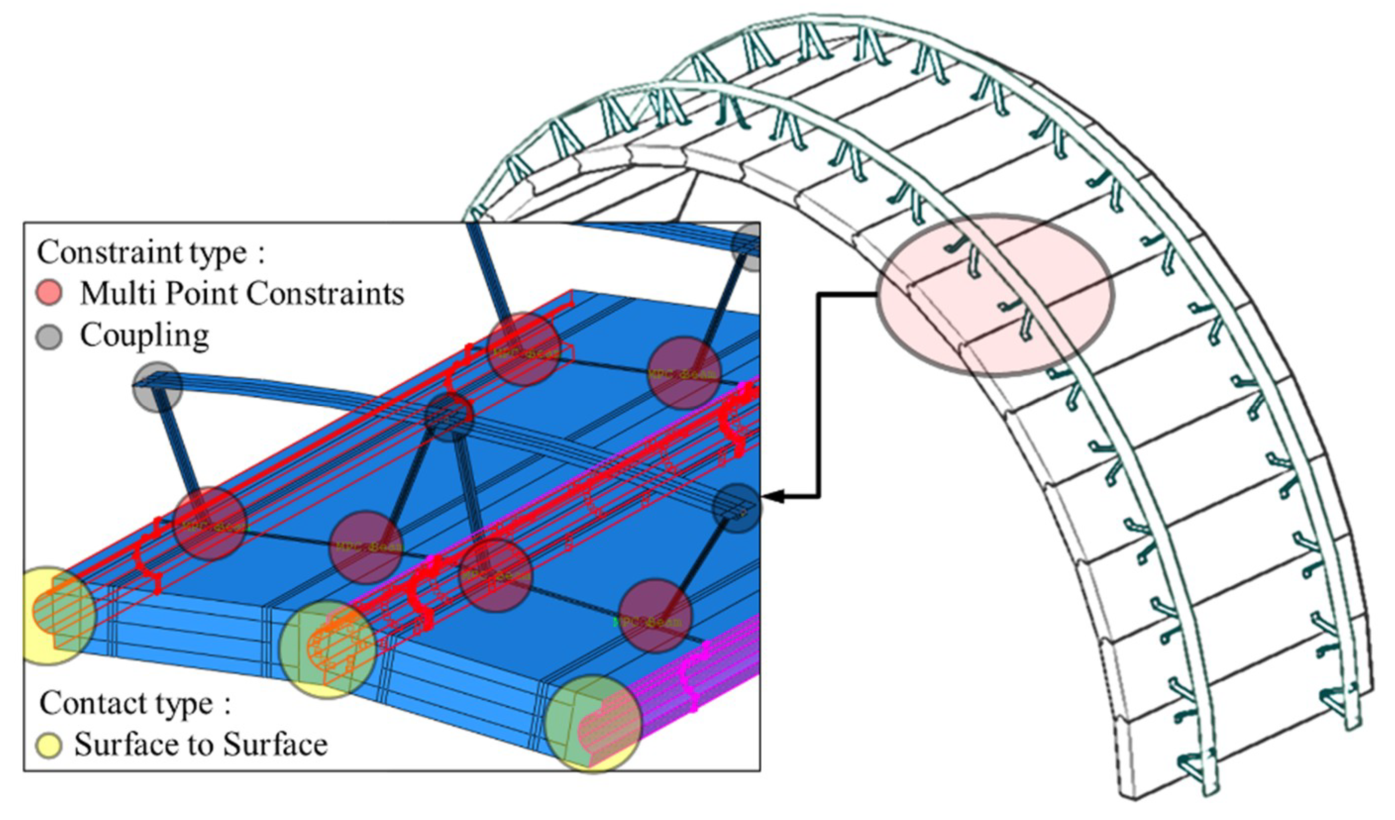
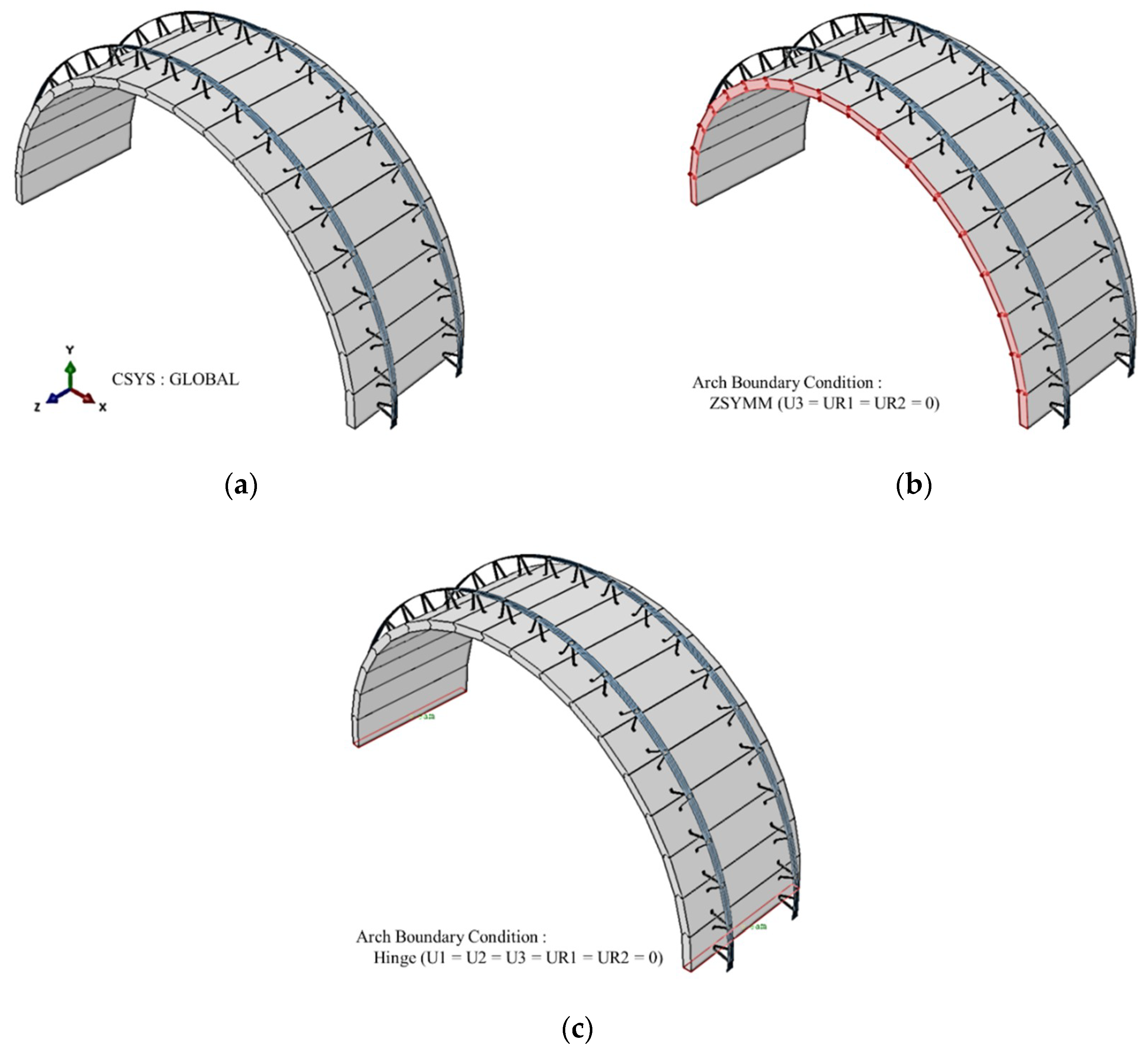
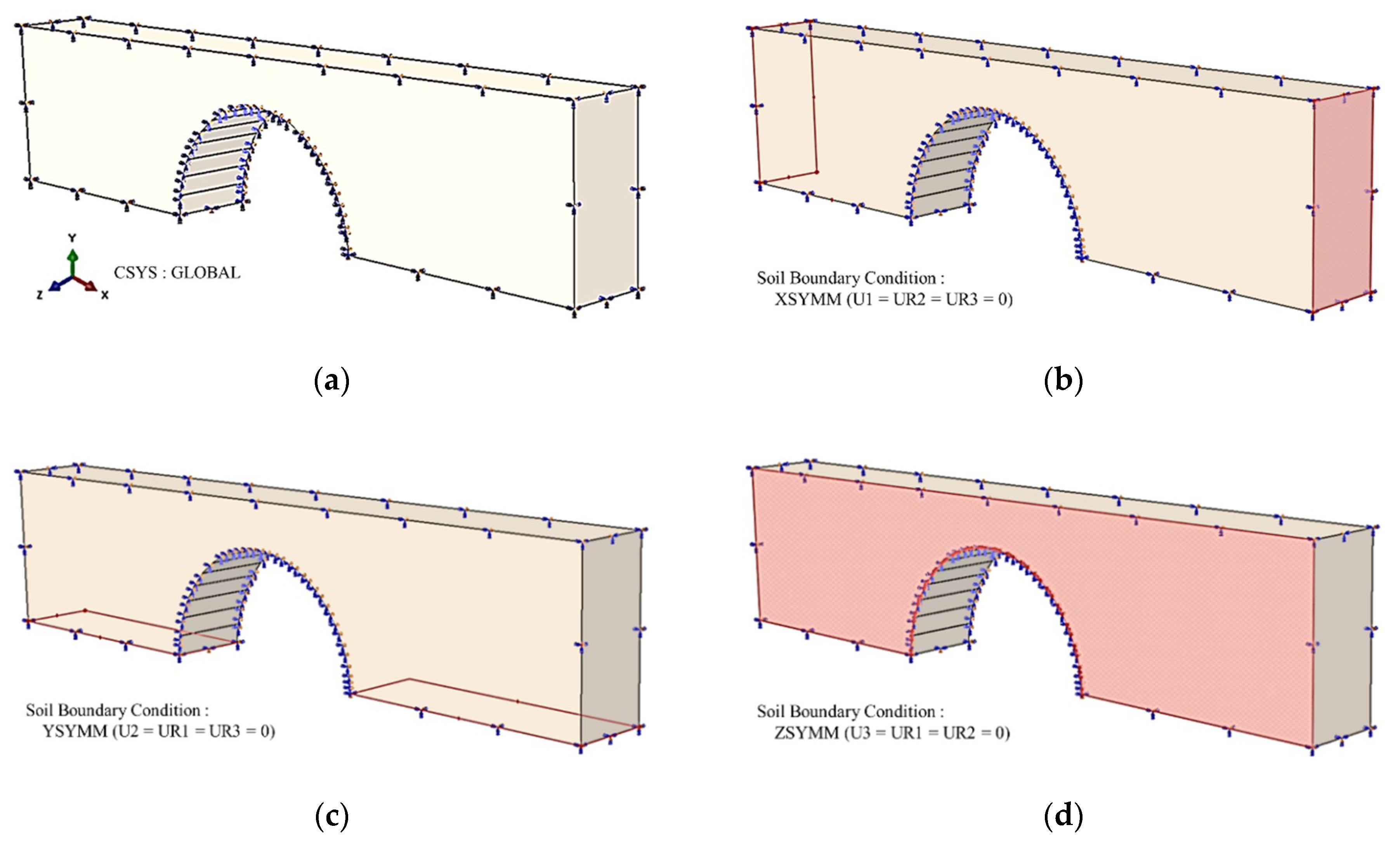
To simulate the behavior of the actual arch bridge, the connection and contact conditions were assigned to each connection, as shown in Figure 12. The surface-to-surface analysis conditions provided by ABAQUS were assigned to the connections between the precast panels, as well as to the contact surface between the precast panel and the backfill soil [16]. Moreover, according to the material properties of each member, a coefficient of friction of 0.4 was used for the connections between the panels [18], and a coefficient of friction of 0.5 was used for the backfill soil and the precast panel. For the precast panels and V-strips, the multi-point constraints (MPC) cause the bolt connection of the panels and the V-strips to act as a beam. The V-strips and outriggers were brought into contact by constraining the degree-of-freedom among the models through point-to-point coupling [16]. As shown in Figure 9, to the structural analysis of the proposed bridge according to the construction step of the backfill soil, each construction step was simulated using the ‘model change’ process provided by ABAQUS. After the generation of each model, the soil mass and bridges were brought into contact. The boundary condition was fixed to the hinge condition at the end of the precast panels (Figure 13). Constraints were applied to the precast panels in the longitudinal direction to achieve model continuity. As shown in Figure 14, with respect to the continuity in the width and length directions, constraints were assigned in the backfill soil width and length directions. In the lower part of the backfill soil model, constraints were applied in the vertical direction.

4. Analysis of Target’s Structure Behavior

To analyze the structural behavior of the proposed arch bridge, the stresses and displacements of the precast panels and outriggers were investigated. The stresses and displacements of the arch bridge members were observed at the center of the cross-section of the precast panels; in the outriggers, they were observed at the connecting part of the V-strips and the center. To determine the stress and displacement positions of the precast panels and outriggers, numbers were assigned from the support precast panels to the arch crown panels as shown in Figure 15. Moreover, the stress and displacement generated in each panel and outrigger, at each construction step, were measured.

4.1. The Result of the Behavior Evaluation of 3D Structural Analysis Model

4.1.1. Precast Panel and Outrigger Stress Results

To assess the behavior of the proposed arch bridge, the stresses of each member of the arch bridge were compared at each construction step. With respect to the stress of each arch bridge member and the precast panels modeled by the solid elements, to compare the stress of each precast arch block and outrigger, the local coordinates of each element were arranged in the local direction of the arch member, and the axial stress (S11) was confirmed.
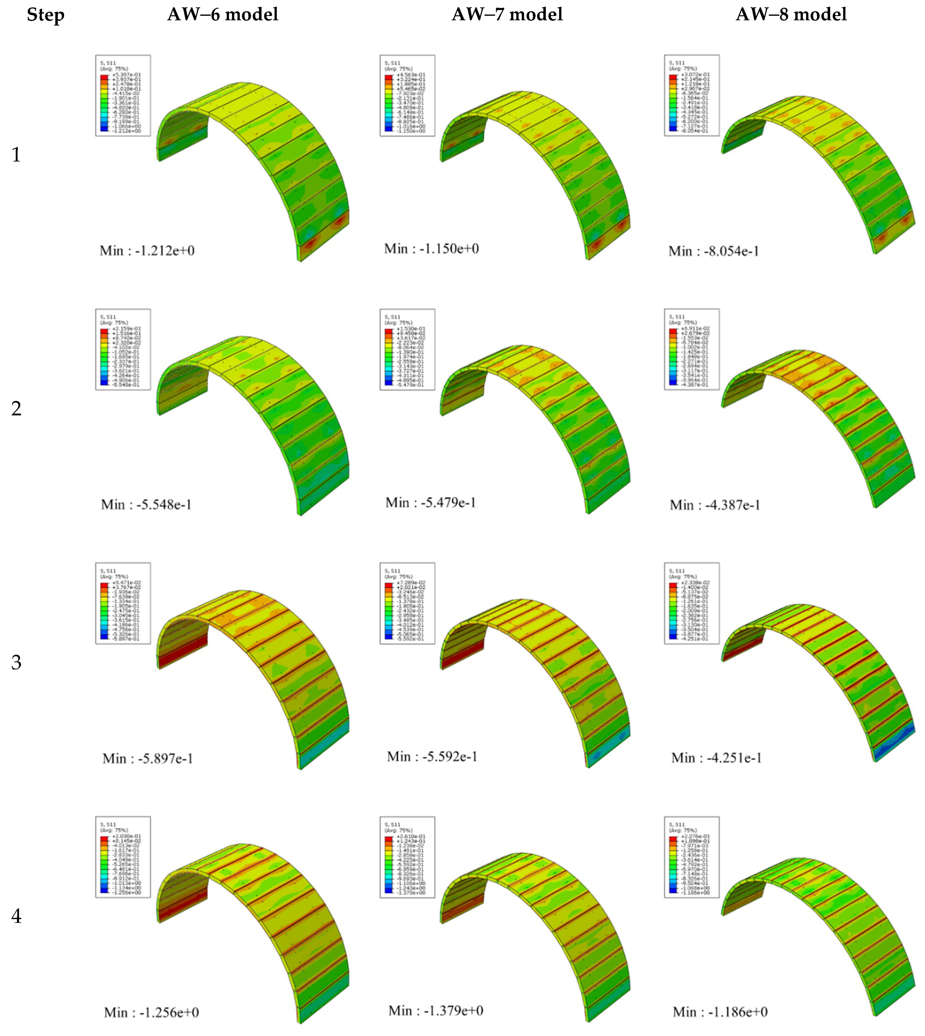
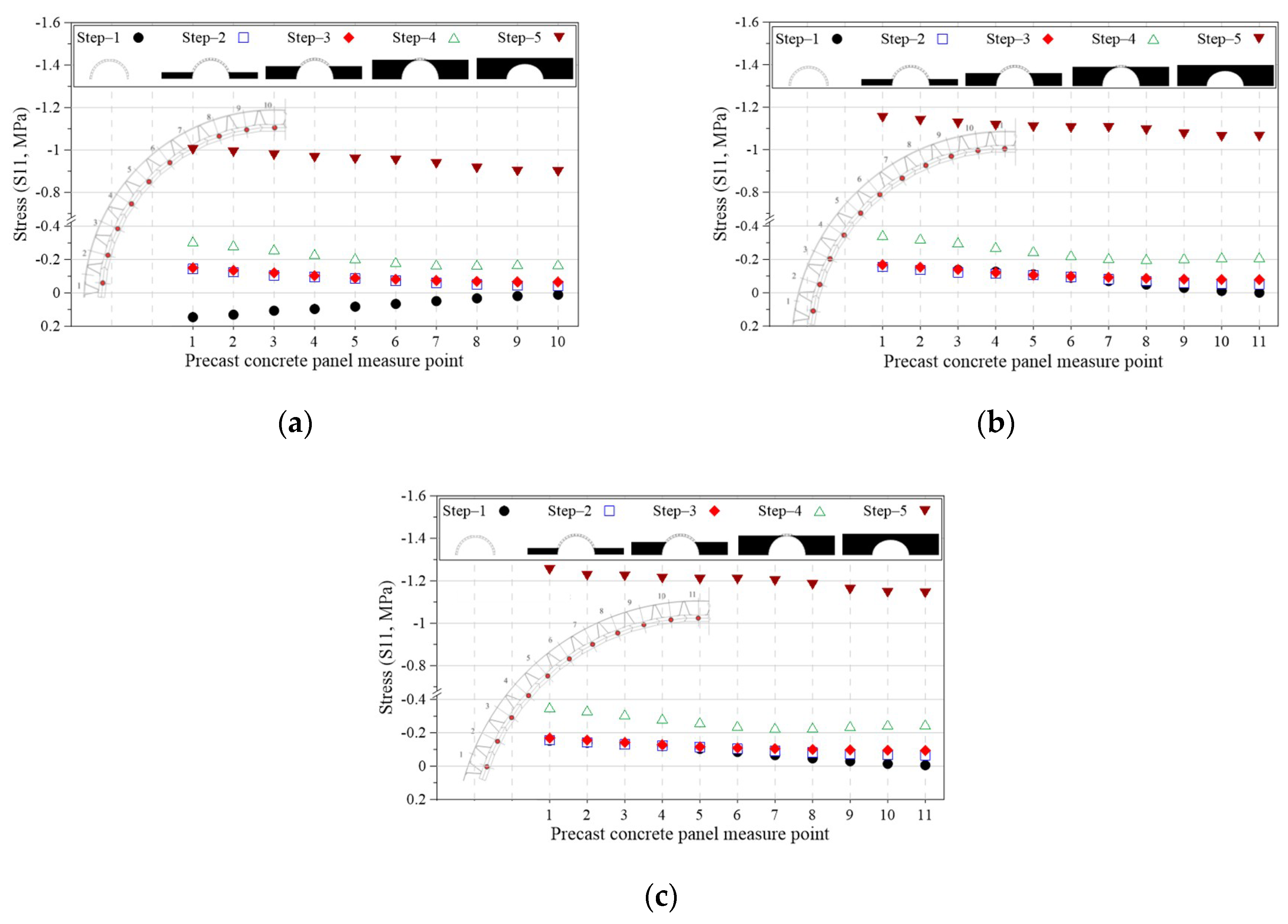
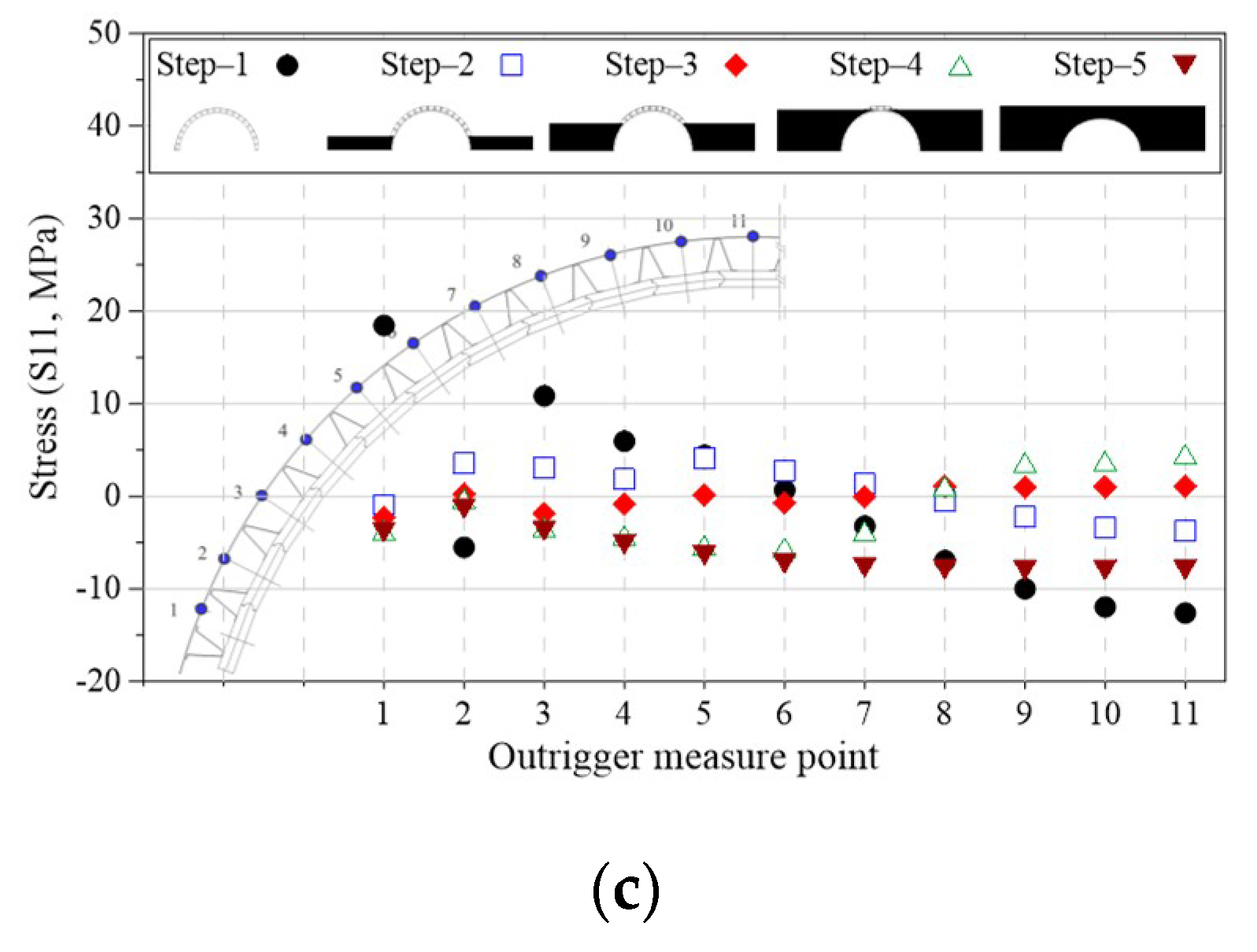
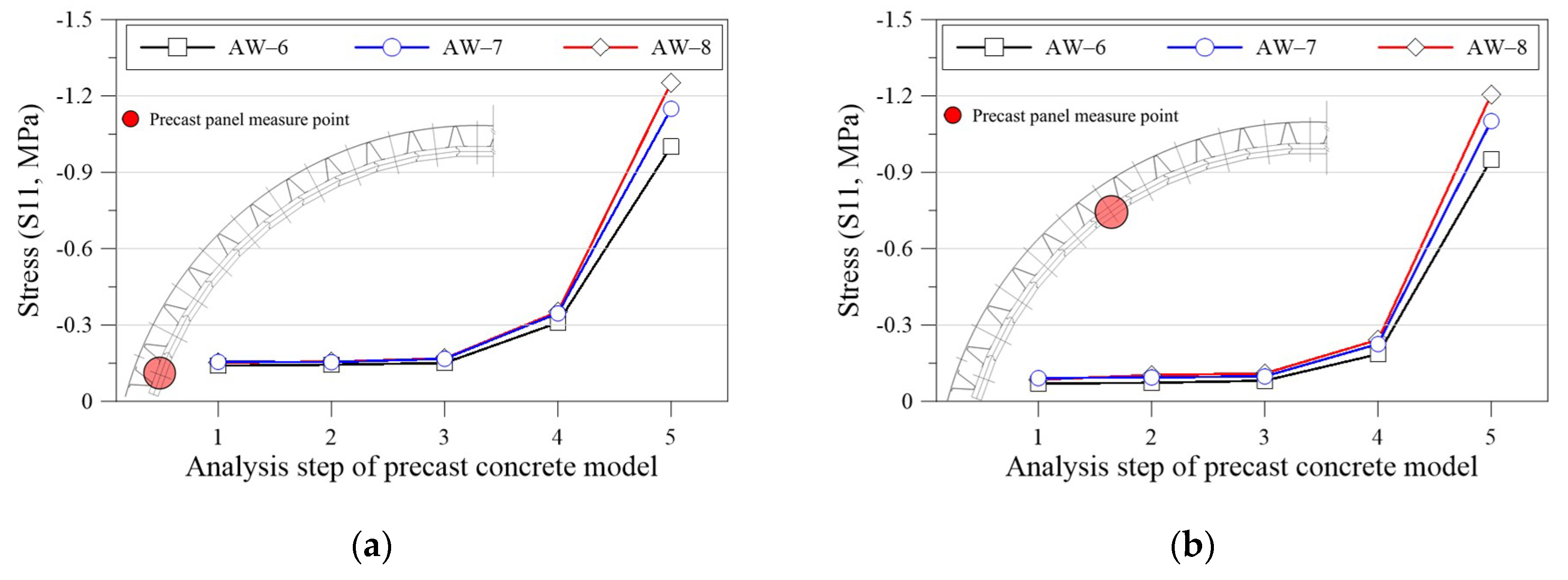
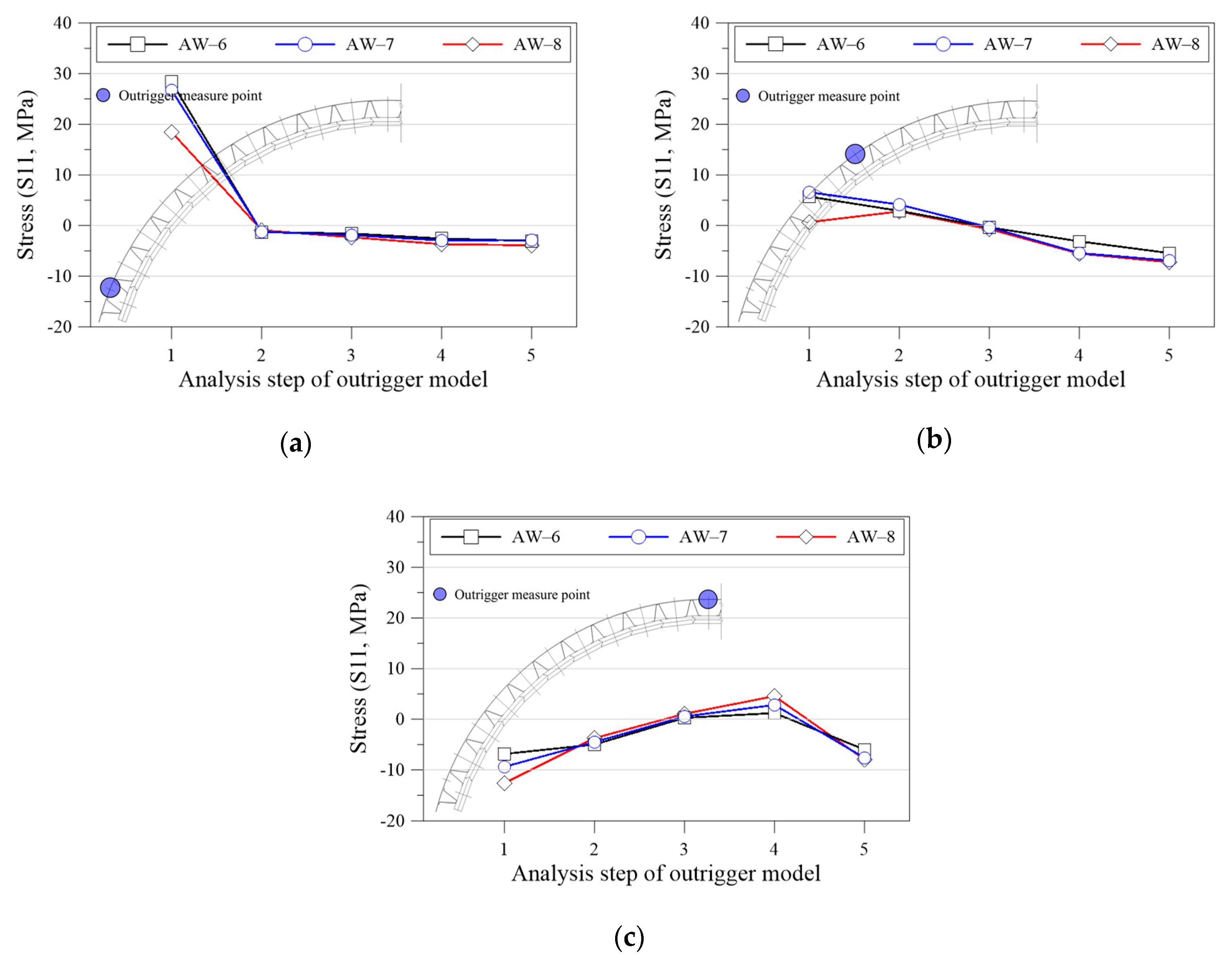
To compare the stress distribution with the stresses at each construction step with respect to the position of the precast panel member, Figure 16 presents the axial stress (S11) distribution of the precast panels at each construction step with respect to the bridge span. Figure 17 and Figure 18 present comparisons of the stresses of the precast panels and outriggers with respect to the arch span. The stresses of the precast panels and the outriggers connected to the precast panels (Figure 17 and Figure 18) were found to be similar, irrespective of the span of the target bridge. Figure 17 presents the stress distribution of each precast panel member with respect to the construction step. As can be seen from the figure, the compressive stress increased in accordance with an increase in the construction step for all of the precast panels that form the arch bridge. In the final step, at which the soil mass was loaded, the compressive force of the precast panels exhibited the largest increase. The soil mass load increased in accordance with an increase in the span. Consequently, the increase in the compressive stress was relatively large. The maximum compressive stress was found to be significantly small, with a value of 1.3 MPa; approximately 10%–30% of the maximum compressive stress was observed at each construction step. In comparison, as shown in Figure 18, the outriggers connected to the precast panels exhibited varied stress distributions at each construction step and each position of the outriggers. The outriggers connected to the precast panels near the support exhibited tensile stress in the self-weight state, and the tensile stress related to the increase of the construction step was reduced. In the final step, a negligible amount of compression was generated. In the outriggers connected to the precast panels around the crown, although the compressive stress was generated, the magnitude of the compressive stress decreased in accordance with an increase in the construction step number. The maximum tensile stress generated in the outrigger was 28.4 MPa, which corresponds to 10% of the steel yield strength in the support outrigger in the self-weight state. Moreover, a compressive stress of 12.6 MPa was generated, which corresponds to 5% of the tensile strength in the crown outrigger.
The stress in the precast panels and outriggers of the proposed arch bridge was generated according to the thrust line and deformation characteristics based on the behavior of the arch bridge. In the self-weight state, the tensile and compressive stress of the outriggers was due to the horizontal displacement of the arch support and the vertical displacement of the crown. Furthermore, in the construction steps and final completion step, the difference between the compressive stress of the precast panels, as well as the tensile and compressive stresses of the outriggers, was reduced. Thus, the precast panels and outriggers demonstrated a structurally-stable stress distribution.

4.1.2. Deformed State and Displacement Results of Precast Panels and Outriggers at Each Construction Step

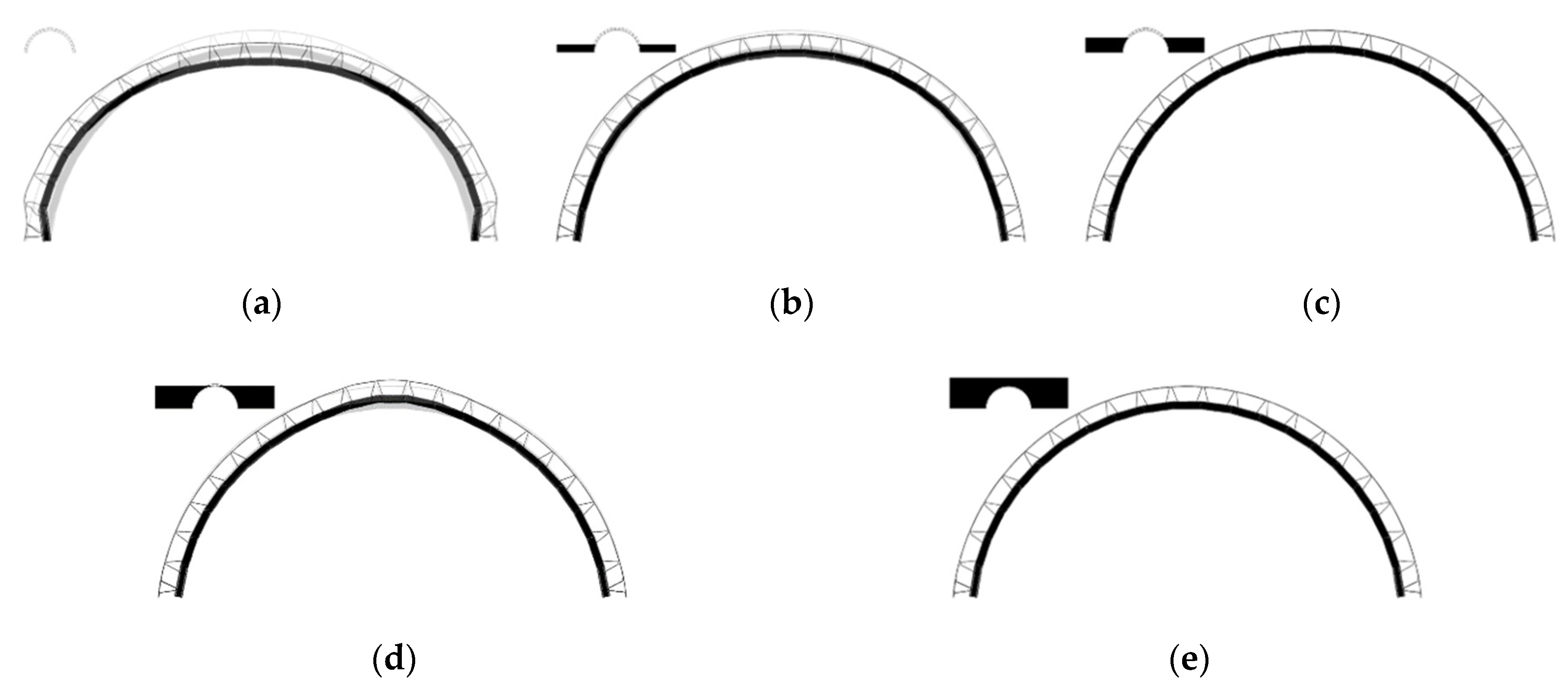
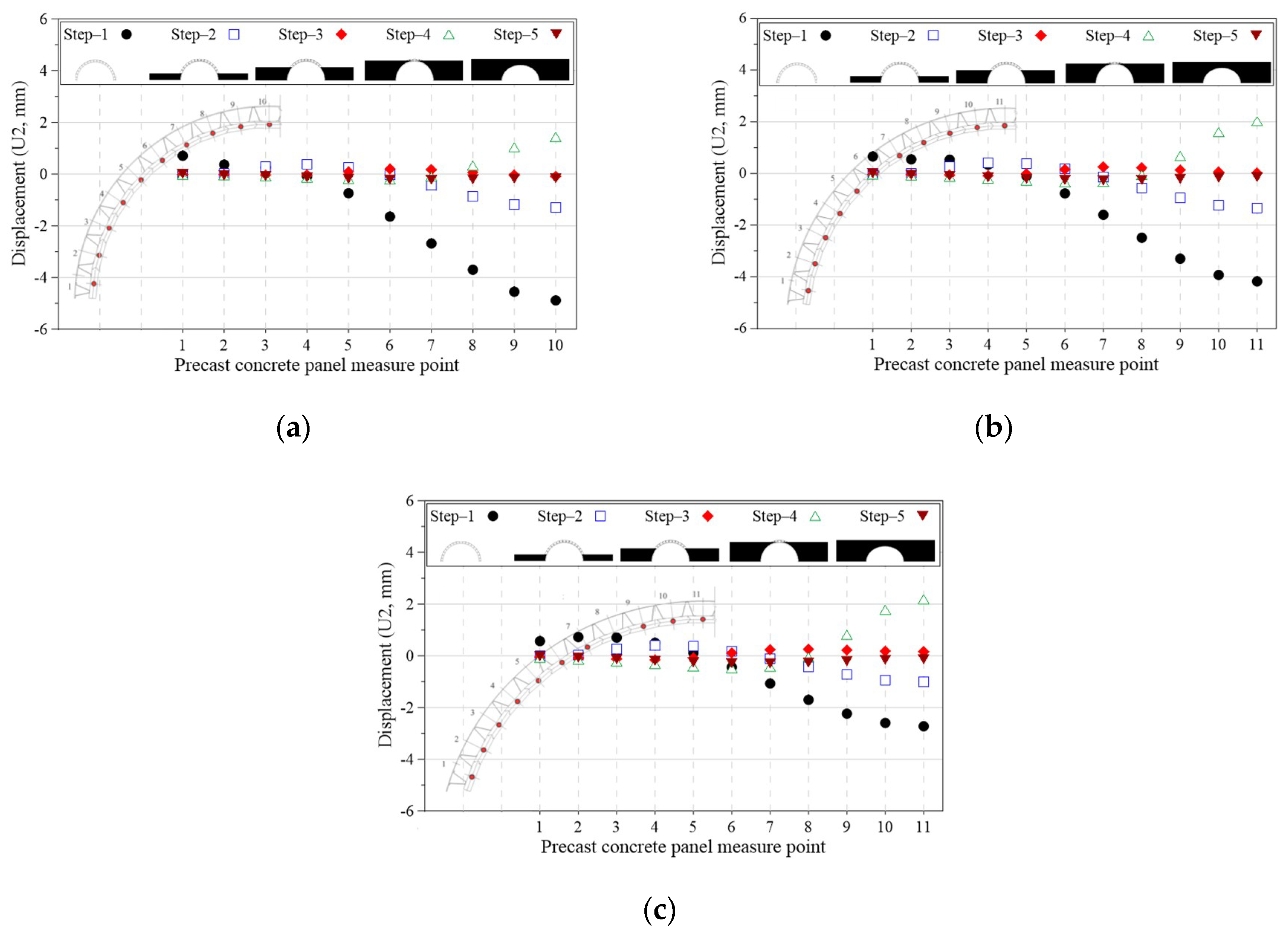
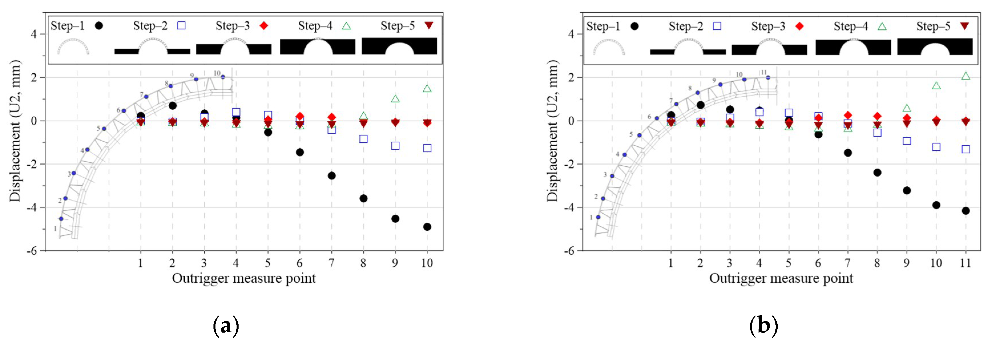
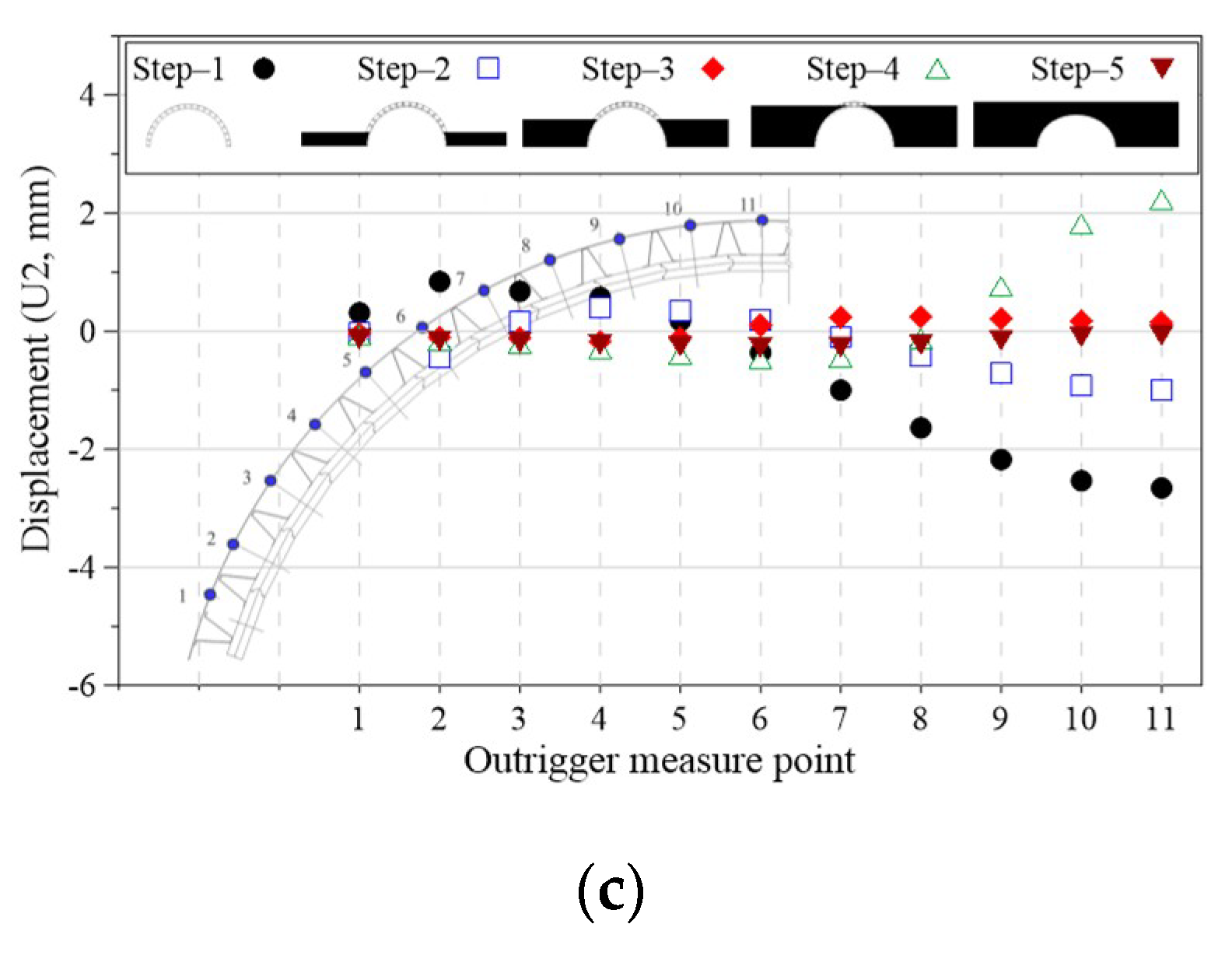
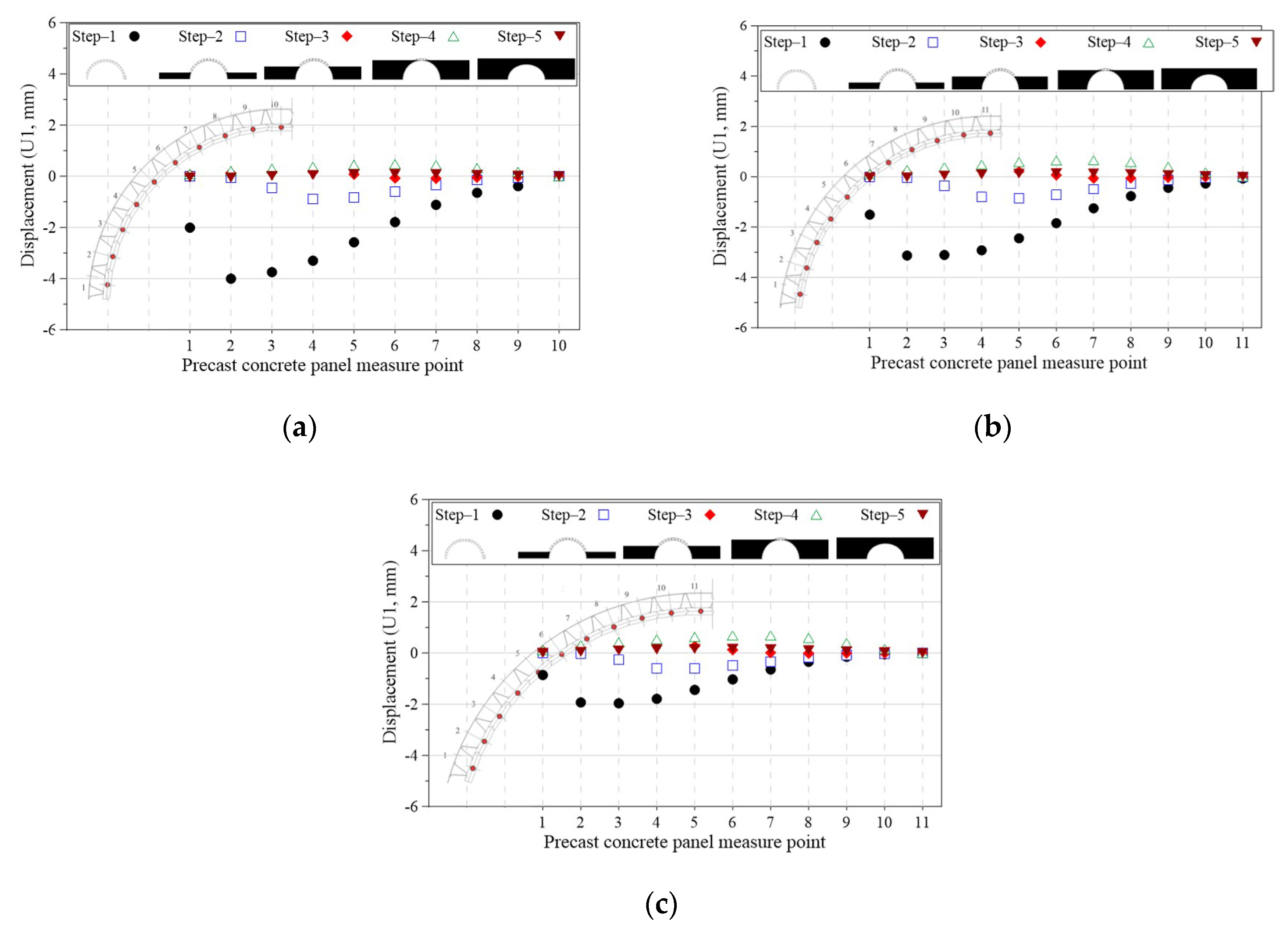
To examine the behavior of the proposed arch bridge at each construction step, Figure 19, Figure 20 and Figure 21 present a comparison of the deformation shapes of the precast, panel-segmented arch bridge with outriggers, with respect to the construction step. Given that the deformation of the bridges that was generated was found to be relatively small, the scale factor (50) was applied to confirm the behavioral characteristics of the proposed arch bridges. As shown in Figure 19, Figure 20 and Figure 21, the deformed states at each construction step of the arch bridges with spans of 6, 7 and 8 m, as examined in this study, were the same. As shown, a relatively large horizontal displacement was observed in the precast panel near the lower support in the self-weight state (Step 1), and a vertical displacement occurred in the upper crown of the precast panel. However, the horizontal and vertical displacements that occurred at the arch bridge support and crown, attributed to the backfill soil and soil mass load during construction, were reduced. A comparison of the deformed states at each construction step of the arch bridge proposed in this study demonstrated that a large displacement and deformation can be generated in the self-weight state, and that the behavior of the arch bridge can be relatively unstable. However, the deformed shapes indicate that the behavior was stabilized depending on the construction step. Figure 22, Figure 23, Figure 24 and Figure 25 present comparisons of the horizontal and vertical displacements of each member of the bridge analyzed with respect to the deformed shapes shown in Figure 19, Figure 20 and Figure 21. As described above, in the model with a span of 6 m, there was a maximum downward vertical displacement of −4.89 mm in the upper part (crown) of the precast panel. Moreover, there were vertical displacements of −4.18 and −2.72 mm in the models with spans of 7 and 8 m, respectively. Additionally, from Steps 2–4, similar to the deformed shapes shown in Figure 20b–d and Figure 21b–d, deformation occurred in the upper part of the arch bridge because of the load effect of the arch bridge backfill soil. Consequently, there was a maximum displacement of 2.19 mm for the model with a span of 8 m, in addition to vertical displacements of 1.43 and 2.02 mm for the models with spans of 6 and 7 m, respectively. In the final construction step, there was a vertical displacement of approximately −0.14 mm due to the load effect of the upper soil mass; the arch bridge exhibited a shape similar to that of the initial state of the initial plan. The vertical displacement results of the outriggers shown in Figure 23 are similar to those of the precast panels described above.
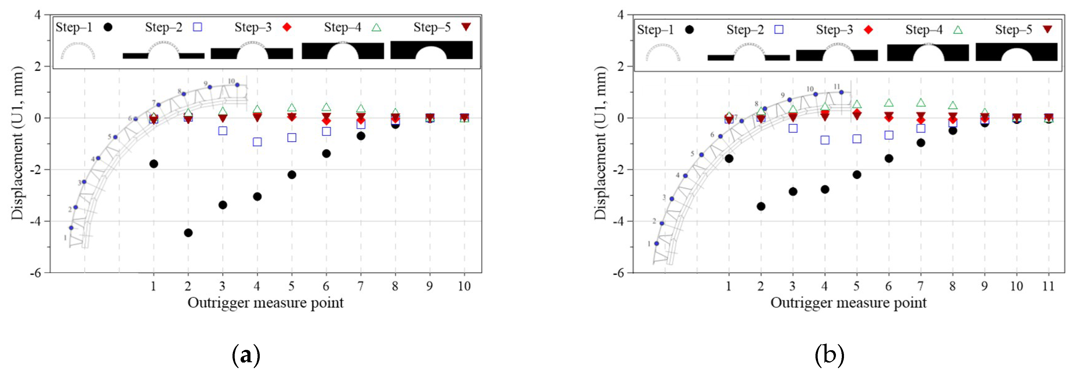
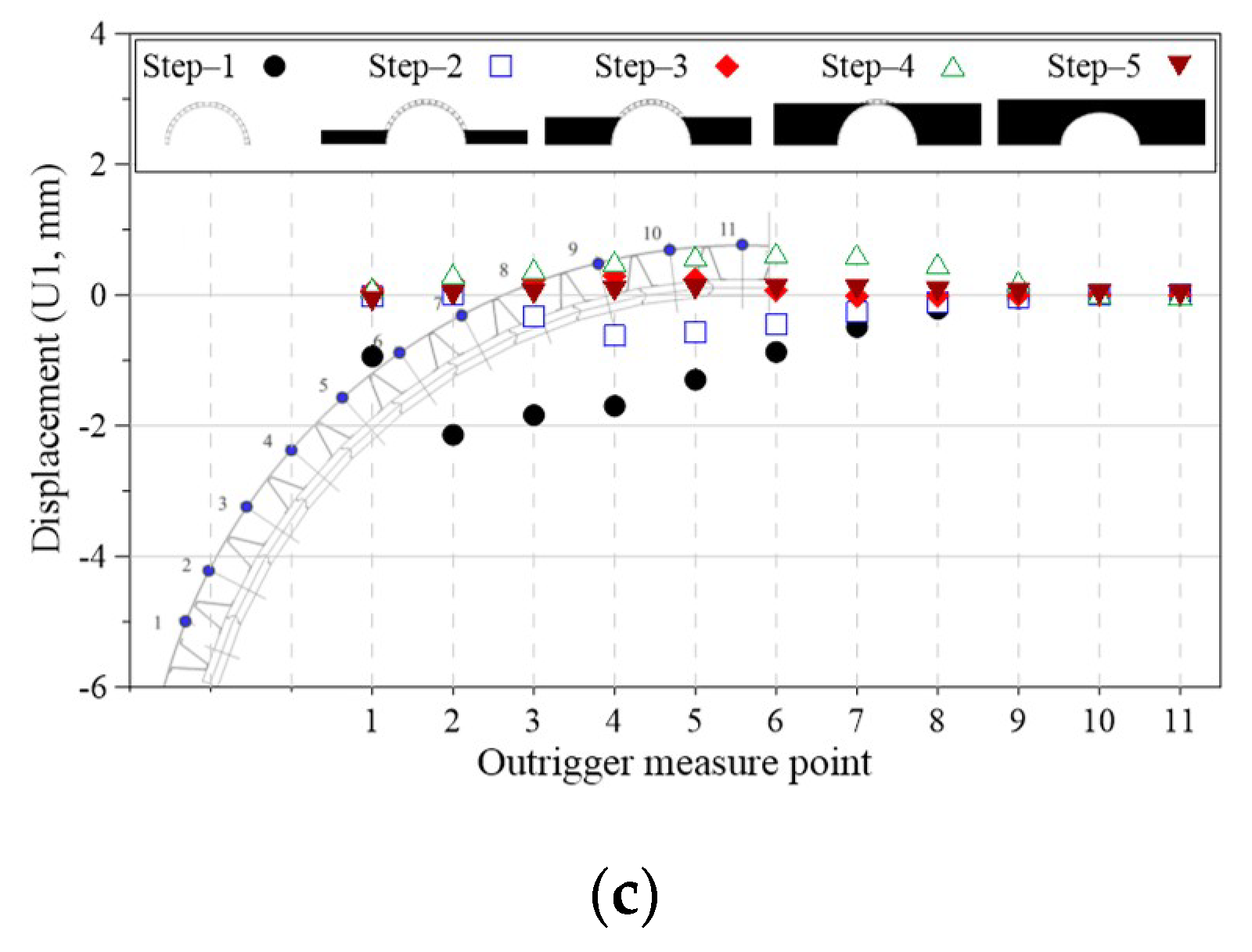
For the bridge model with a span of 6 m in a self-weight state (Step 1), a horizontal displacement of 4 mm was generated outward from the precast panel near the support; contrastingly, there were horizontal displacements of −3.13 and −1.97 mm in the bridge models with spans of 7 and 8 m, respectively. Additionally, in Steps 2–5, i.e., the construction of backfill soil and upper soil mass after the self-weight state, the precast panel near the support exhibited a horizontal displacement of approximately ±1 mm compared to the initial state of the initial plan. The horizontal displacement results of the outriggers shown in Figure 25 were similar to those of the precast panels.
The 3D structural analysis results of the proposed arch bridge indicate that for the same heights, there were changes in the rise ratios in accordance with the changes in span length. In the arch bridge with a span of 6 m, which had the largest rise ratio, the displacement response of the proposed arch bridge generated by the horizontal load due to the self-weight and soil mass load was relatively large. This indicates that the horizontal and vertical displacements generated in the self-weight and initial construction step of the proposed arch bridge were relatively small, and that the bridge exhibited stable arch behavior after the upper soil mass’s construction.

4.1.3. Precast Panel and Outrigger Thrust Line Calculations

The thrust line expresses the flow of force, which is dependent on the internal force and the external load. As with the evaluation of the stability of the compression member, the stability of an arch structure can be evaluated depending on whether the thrust exists in the central kern of the elastic area [8,9]. In the case of the proposed arch bridge, as steel outriggers are installed on the outer part of the precast panel, the tensile resistance of the outriggers can ensure structural stability, even when the thrust line deviates from the underside of the precast panel. Therefore, given that the proposed precast, panel-segmented arch bridge with outriggers can have a relatively flexible structure depending on the effect of the segmented precast panels, its stability can be determined according to its structural behavior using the thrust line. To compare the thrust lines according to the conceptual arch behavior of the proposed arch bridge with the behavior exhibited during the structural analysis, the thrust lines were compared at each construction step using the stress results of the bridges with spans of 6, 7 and 8 m obtained from the 3D structural analysis. The axial forces acting on the outriggers and those acting on the precast panels were calculated from the structural analysis results; the thrust line for each construction step was calculated using a proportional equation according to the distance from the origin (Figure 26). As shown in Figure 26, the thrust line of the arch bridge proposed in this study demonstrated a similar behavior to the thrust line of the arch bridge conceptually shown in Figure 2, Figure 3, Figure 4 and Figure 5. Under the self-weight condition, there was a relatively large displacement near the support of the bridge and arch crown, as indicated by the structural analysis results; thus, the thrust line was directed outward from the precast panels at the arch crown and the support. However, the load acting on the outer side of the precast panels was converted into a compressive force at the arch panels, and the thrust line acting on the proposed bridge also acted within the precast panels. Even in the final loading state, the same behavior was observed. As shown in Figure 26, with an increase in the span, there were relatively small changes in the thrust line behavior, which is similar to the case of the deformation of the arch bridge. Hence, if the rise ratio of the arch bridge is large, as in the deformation of the abovementioned arch bridge, the load on the arch bridge panels is relatively large; this causes the thrust line to be located outside of the arch bridge precast panels. However, with an increase in the span of the arch bridge, the arch thrust line changed such that it was located inside the concrete panels. This confirms that the structural stability of the target arch bridge can be secured through the tensile resistance effect of the outrigger installed externally to the precast concrete arch panel of the proposed arch bridge. Accordingly, the precast panel arch bridge with the proposed outrigger demonstrated a stable and structurally-effective performance.

4.2. Stress Comparison by Arch Member According to Rise Ratio of 3D Structural Analysis Model

Based on the analysis of the behavior of the proposed arch bridge with respect to the span, the target arch bridge was confirmed to exhibit a stable behavior with respect to the structural role of each member and the behavioral characteristics of the bridge. To compare the behavioral characteristics of the members of the proposed arch bridge, the possible stress behaviors of the target arch bridge members were compared with respect to the influence of the arch height (rise ratio) on the span of the target arch bridge, as presented in this section. With respect to the stress behaviors of the target arch bridge at different construction steps, Figure 27 and Figure 28 present comparisons of the stresses with respect to the rise ratios of the precast panels and outriggers. Figure 27 and Figure 28 present comparisons of the stresses with respect to the construction steps of the precast panels and outriggers for the precast panels near the support, arch crown precast panels and side precast panels, in which the maximum horizontal displacement and vertical displacement of the arch bridge occur. As shown in Figure 27 and Figure 28, the stresses of the precast panels and outriggers varied with respect to the construction step; they exhibited similar stress levels, irrespective of the span.
In the precast panels, with an increase in the construction step, the stress on the panels increased, irrespective of the position of the precast panels. However, in the outriggers installed in the precast panels near the support, when the largest tensile stress was applied to the self-weight state and its position changed to the upper crown, the tensile stress generated by the self-weight in the outriggers was reduced. Moreover, with an increase in the construction step number, the tensile stress decreased, and the compressive stress acted.
In the case of the arch crown and the side outriggers, the tensile and compressive stresses were generated under the initial self-weight state or the initial backfill, soil loaded state. However, with an increase in the construction step number, and when subject to the upper soil’s mass load, the target outrigger was in a compressed state. The abovementioned behavior of the outrigger behavior reflects the structural features of the proposed arch bridge. As validated by the thrust lines and deformation shapes described above, the stress behavior characteristics of each arch bridge member were in accordance with the behavior of the outriggers installed external to the precast panels. Given that the difference between the span and the rise ratio of the target bridge was small, the stress of the precast panels and outriggers shown in Figure 27 and Figure 28 was relatively small. From these results, the arch behavior of the proposed arch bridge can be confirmed with respect to its construction step.

5. Conclusions

This paper proposes a precast, panel-segmented arch bridge with outriggers that form the cross-section and shape of the arch, in which the precast panel members and outriggers resist the bending moment generated during construction and the compressive force generated during use. In this study, the stability of the arch bridge was evaluated with respect to the construction step and rise ratio during construction; the performances of the target arch bridges were determined by conducting a 3D, non-linear, finite element analysis. The conclusions are as follows:
(1) The proposed precast, panel-segmented arch bridge with outriggers consists of precast panel members subject to compressive force and continuous rib-type outriggers connected to the precast panels that resist the tensile force. In this bridge type, the compressive and tensile forces applied to the arch bridge, with respect to the construction step, were efficiently transmitted through the concrete panels and continuous rib-type outriggers.
(2) Based on 3D structural analysis results of the proposed arch bridge, the stresses in the precast panels and outriggers were in accordance with the thrust line and deformation characteristics based on the behavior of the arch bridge. The outriggers’ tensile and compressive stresses were caused by the horizontal displacement of the arch support and the vertical displacement of the crown in the self-weight state. Furthermore, the compressive stress of the precast panel and the tensile and compressive stress of the outrigger at the final construction step exhibited structurally stable stress distributions, because of the decreased difference in all of the members.
(3) Based on the results, in the self-weight state, there was a relatively large displacement near the support of the bridge and arch crown, causing the thrust line to be located outside the precast panels in the arch crown and the support. With an increase in load with respect to the construction step, the thrust line was found to act inside the precast panels at the final construction step.
(4) There was a relatively large horizontal displacement in the precast panels near the lower support in the self-weight state, and there was a vertical displacement in the upper crown precast panels. However, the horizontal displacement in the arch bridge was reduced because of the backfill soil and soil mass load during construction, in addition to the vertical displacement in the arch crown. The proposed arch bridge exhibited different behaviors with respect to changes in the rise ratio. However, given that the deformation and member forces were very small, the proposed arch bridge was considered to have a stable structural behavior after increasing the construction step number and applying the upper soil mass load.
In the proposed arch bridge, the applied span and structural behavior can be varied with the precast panel installation method. In future work, the efficiency and applicability of the proposed arch bridge should be examined through a detailed review of the characteristics of the precast panel connections and members. Moreover, various analyses and empirical experiments should be conducted to determine the structural behavior.

Author Contributions

S.H.J. and J.-H.A. conceived the idea and designed the framework; K.-I.C. and J.H. designed the numerical models; S.H.J. and K.-I.C. performed the analyses; J.-H.A. and J.H. analyzed the data; and S.H.J. and J.-H.A. wrote the paper.

Funding

This work is supported by the Korea Agency for Infrastructure Technology Advancement (KAIA) grant funded by the Ministry of Land, Infrastructure and Transport (grant 19CTAP-C151892-01).

Conflicts of Interest

The authors declare no conflict of interest.

References

  1. Block, P. Equilibrium Systems: Studies in Masonry Structure. Master’s Thesis, Massachusetts Institute of Technology, Cambridge, MA, USA, 2005. [Google Scholar]
  2. Block, P.; Ciblac, T.; Ochsendorf, J. Real-time limit analysis of vaulted masonry buildings. Comput. Struct. 2006, 84, 1841–1852. [Google Scholar] [CrossRef]
  3. Heyman, J. The Masonry Arch; Ellis Horwood Ltd.: Chichester, UK, 1982. [Google Scholar]
  4. Kim, N.H.; Koh, H.M.; Hong, S.G. Study on Structural Behavior of Traditional Stone Bridges. Comput. Struct. Eng. Inst. Korea 2008, 78–83. (In Korean) [Google Scholar]
  5. Collings, D. Steel-Concrete Composite Bridges; ICE: Washington, DC, USA, 2005. [Google Scholar]
  6. Brencich, A.; Morbiducci, R. Masonry Arches: Historical Rules and Modern Mechanics. Int. J. Archit. Herit. 2007, 1, 165–189. [Google Scholar] [CrossRef]
  7. Loo, Y.C.; Yang, Y. Cracking and failure analysis of masonry arch bridges. J. Struct. Eng. ASCE 1991, 117, 1641–1659. [Google Scholar] [CrossRef]
  8. Kim, N.H.; Koh, H.M.; Hong, S.G. Development of a structural safety evaluation system for stone voussoir arch bridges. J. Comput. Struct. Eng. Inst. Korea 2009, 22, 15–23. (in Korean). [Google Scholar]
  9. Lacidogna, G.; Accornero, F. Elastic, plastic, fracture analysis of masonry arches: A multi-span bridge case study. Curved Layer Struct. 2018, 5, 1–9. [Google Scholar] [CrossRef] [Green Version]
  10. Cho, Y.S. Development of Temporary Arch Bridges by Using Snap-Fit GFRP Composite Decks. Master’s Thesis, Kookmin University, Seoul, Korea, 2008. (In Korean). [Google Scholar]
  11. Tan, G.E.; Ong, T.B.; Ong, C.Y.; Choong, K.K. Development and Standardisation of New Precast Concrete Open Spandrel Arch Bridge System. In Proceedings of the 37th IABSE Symposium in Madrid, Madrid, Spain, 3–5 September 2014; pp. 799–806. [Google Scholar]
  12. Ong, C.Y.; Choong, K.K.; Tan, G.E.; Ong, T.B. Precast Concrete Closed Spandrel Arch Bridge System As Viable Alternative to Conventional Beam Bridge System. Appl. Mech. Mater. 2015, 802, 261–266. [Google Scholar]
  13. Lee, S.M.; Shin, J.S.; Jeon, S.J.; Han, M.Y. Optimal Design of Arch Rise to Span Ratio in Arch Bridges. Proc. Korea Concr. Inst. 2012, 24, 541–542. (In Korean) [Google Scholar]
  14. Bernini, J.; BEBO of America, Inc. Overfilled precast concrete arch bridge structures. In Proceedings of the International Bridge Conference and Exhibition, Zurich, Switzerland, 15–17 June 2000. [Google Scholar]
  15. Canadian Standards Association. CAN/CSA-S6-14: Canadian Highway Bridge Design Code, Rexdale, Ontario; Canadian Standards Association: Toronto, ON, Canada, 2014. [Google Scholar]
  16. ABAQUS. Abaqus Analysis User Manual, Version 6.14; Dassault Systems Simulia Corp; ABAQUS Inc.: Johnston, UI, USA, 2014. [Google Scholar]
  17. Hognestad, E. A Study of Combined Bending Axial Load in Reinforced Concrete Members; Bulletin Series; Engineering Experimental Station; The University of Illinois: Urbana, IL, USA, 1951; Volume 49. [Google Scholar]
  18. BSI British Standards. BS 5975: Code of Practice for Temporary Works Procedures and the Permissible Stress Design of Falsework; BSI British Standards: London, UK, 2008. [Google Scholar]
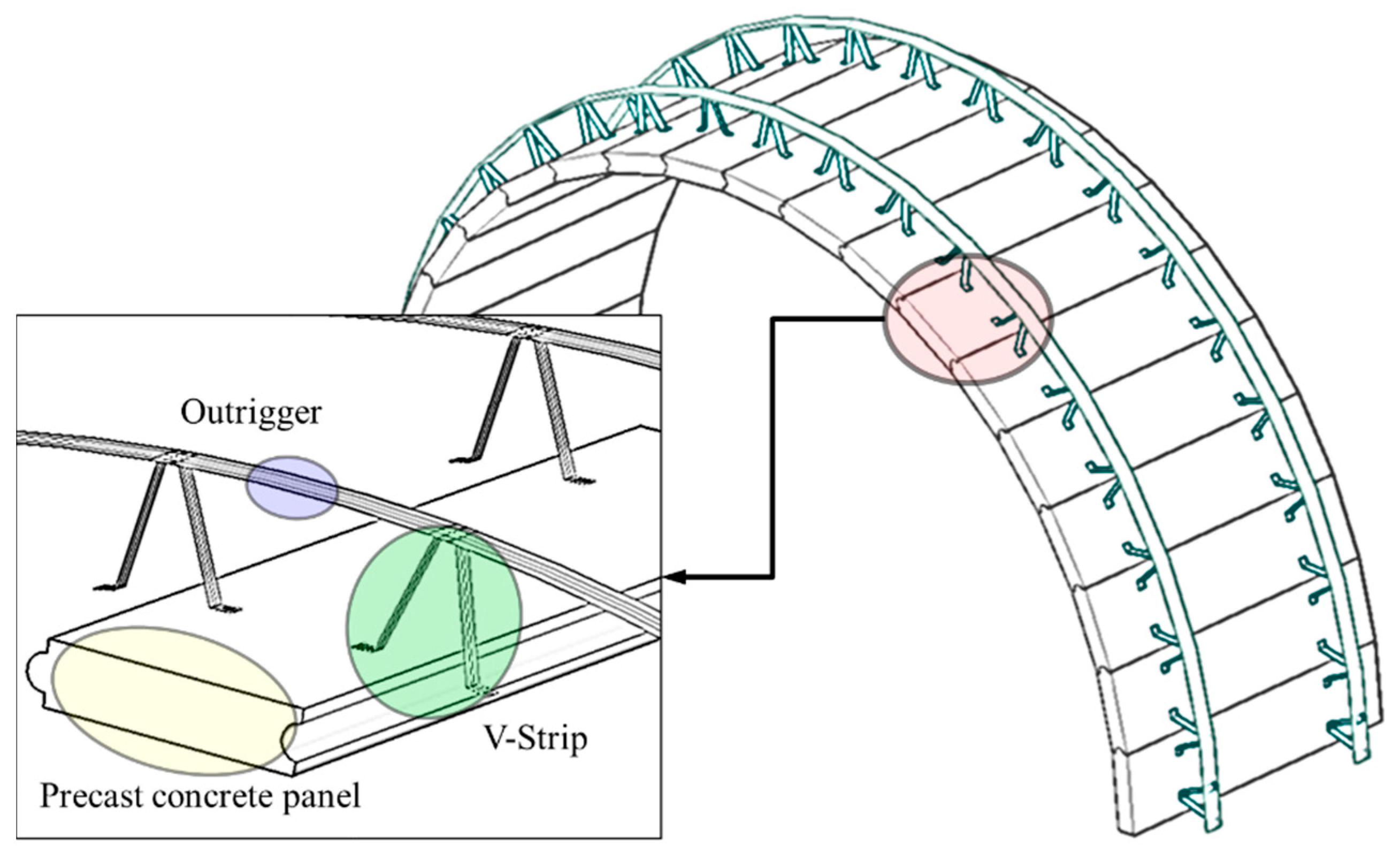
Figure 1. Precast, panel-segmented arch bridge with outriggers.
Applsci 09 04646 g001
Figure 2. Thrust line of arch bridge under self-weight: (a) a precast, three-hinged concrete arch and (b) a precast outrigger panel arch.
Applsci 09 04646 g002
Figure 3. Thrust line of arch bridge under self-weight and lower-side earth pressure (during construction): (a) a precast, three-hinged concrete arch and (b) a precast, outrigger panel arch.
Applsci 09 04646 g003
Figure 4. Thrust line of arch bridge with self-weight and earth pressure (after construction): (a) a precast, three-hinged concrete arch and (b) a precast outrigger panel arch.
Applsci 09 04646 g004
Figure 5. Thrust line of arch bridge with self-weight, earth pressure and additional load (after construction): (a) precast, three-hinged concrete arch and (b) a precast outrigger panel arch.
Applsci 09 04646 g005
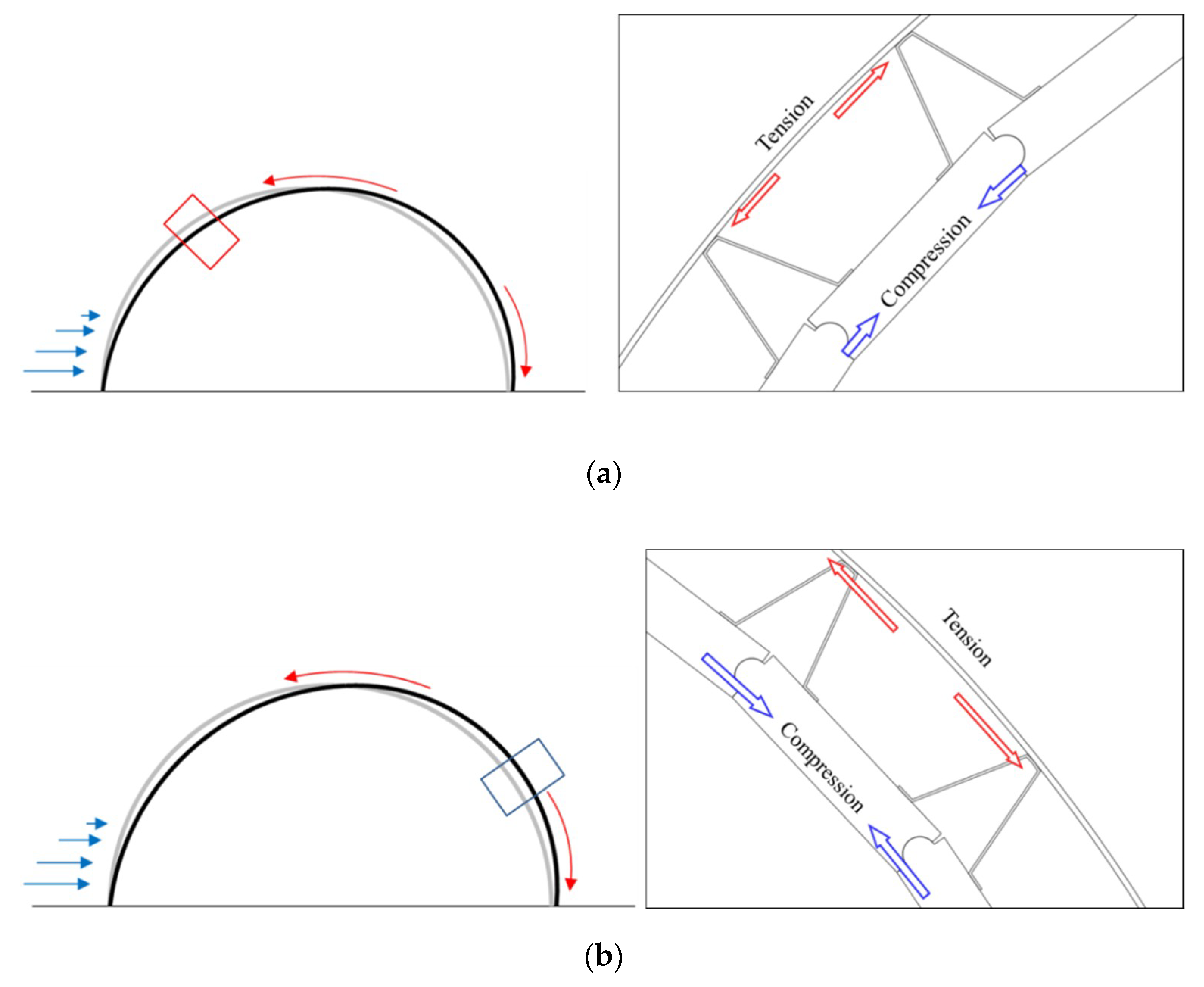
Figure 6. Conceptual diagram of the behavior of the one-sided backfill soil of a precast, panel-segmented arch bridge with outriggers: (a) behavior of left-side arch bridge member during one-sided backfill construction and (b) behavior of right-side arch bridge member during one-sided backfill construction.
Applsci 09 04646 g006
Figure 7. Specifications of target bridge for 3D structural analysis (units: mm): (a) precast, panel-segmented arch bridge with outriggers; (b) outrigger and V-strip specification; (c) precast panel specifications.
Applsci 09 04646 g007
Figure 8. Structural analysis steps for a precast, panel-segmented arch bridge with outriggers.
Applsci 09 04646 g008
Figure 9. Analysis model of a precast, panel-segmented arch bridge with outriggers: (a) 3D structural analysis model; (b) precast panel and outrigger details; (c) Step 2 loading condition model; (d) Step 5 loading condition model.
Applsci 09 04646 g009
Figure 10. Precast panel stress–strain relationship with a design compressive strength of 35 MPa.
Applsci 09 04646 g010
Figure 11. Stress–strain relationships of outriggers and V-strip steel.
Applsci 09 04646 g011
Figure 12. Structural analysis model contact and constraints of precast, panel-segmented arch bridge with outriggers. In the inset, multi-point constraints are shown in red, coupling constraints in grey, and surface-to-surface contact in yellow.
Applsci 09 04646 g012
Figure 13. Boundary conditions of arch bridge model: (a) arch model; (b) arch boundary condition: ZSYMM; (c) arch boundary condition: hinge.
Applsci 09 04646 g013
Figure 14. Boundary conditions of backfill soil model: (a) soil model; (b) soil boundary condition: XSYMM; (c) soil boundary condition: YSYMM; (d) soil boundary condition: ZSYMM.
Applsci 09 04646 g014
Figure 15. Confirmed positions from member-unit structural analysis of outrigger and precast panel: (a) 6 m arch; (b) 7 m arch; (c) 8 m arch.
Applsci 09 04646 g015
Figure 16. Maximum stress of precast panel at construction Steps 1–5 for bridge models with arch widths of 6 (AW-6), 7 (AW-7) and 8 m (AW-8).
Applsci 09 04646 g016aApplsci 09 04646 g016b
Figure 17. Stress of each precast concrete panel measure position with respect to the construction step (S11) for models with spans of: (a) 6 m; (b) 7 m; (c) 8 m.
Applsci 09 04646 g017
Figure 18. Stress of each outrigger position with respect to the construction step (S11) for models with spans of: (a) 6 m; (b) 7 m; (c) 8 m.
Applsci 09 04646 g018aApplsci 09 04646 g018b
Figure 19. Behavior of the arch bridge with a span of 6 m with respect to the analysis step (scale factor: 50): (a) Step 1; (b) Step 2; (c) Step 3; (d) Step 4; (e) Step 5.
Applsci 09 04646 g019
Figure 20. Behavior of arch bridge with a span of 7 m with respect to the analysis step (scale factor: 50): (a) Step 1; (b) Step 2; (c) Step 3; (d) Step 4; (e) Step 5.
Applsci 09 04646 g020
Figure 21. Behavior of arch bridge with a span of 8 m with respect to the analysis step (scale factor: 50): (a) Step 1; (b) Step 2; (c) Step 3; (d) Step 4; (e) Step 5.
Applsci 09 04646 g021aApplsci 09 04646 g021b
Figure 22. Vertical displacement (U2) with respect to the construction step and the precast position for models with spans of: (a) 6 m; (b) 7 m; (c) 8 m.
Applsci 09 04646 g022
Figure 23. Vertical displacement (U2) with respect to the construction step and outrigger position for models with spans of: (a) 6 m; (b) 7 m; (c) 8 m.
Applsci 09 04646 g023aApplsci 09 04646 g023b
Figure 24. Horizontal displacement (U1) with respect to the construction step and precast panel position for models with spans of: (a) 6 m; (b) 7 m; (c) 8 m.
Applsci 09 04646 g024
Figure 25. Horizontal displacement (U1) with respect to construction step and outrigger position for models with spans of: (a) 6 m; (b) 7 m; (c) 8 m.
Applsci 09 04646 g025aApplsci 09 04646 g025b
Figure 26. Thrust line with respect to arch bridge span for each model: (a) 6 m span; (b) 7 m span; (c) 8 m span.
Applsci 09 04646 g026
Figure 27. Stress behavior of precast panels with respect to the construction step and rise ratio: (a) arch support; (b) near arch side; (c) arch crown.
Applsci 09 04646 g027aApplsci 09 04646 g027b
Figure 28. Stress behavior of outriggers with respect to the construction step and rise ratio: (a) arch support; (b) near arch side; (c) arch crown.
Applsci 09 04646 g028
Table 1. Specifications of target bridge for 3D structural analysis, including arch width (AW), arch height (AH), outrigger and soil widths (OW, SW), V-strip width (VW), V-strip height (VH), soil cover depth (SD), rise ratio (RR).
AW (m)AH (m)OW, SW (m)VW (mm)VH (mm)SD (m)RR
6.3 (6 m)3.06.7304.5234.21.20.48 (0.5)
7.2 (7 m)3.27.8302.5244.20.44 (0.45)
8.0 (8 m)3.08.6296.5247.20.38 (0.4)
Table 2. Material properties of arch members and fill material.
CategoryPrecast Concrete PanelsOutriggers and V-StripsBackfill Soil and Fill
Compressive strength (MPa)35--
Yield strength (MPa)-280-
Tensile Strength (MPa)4.74450-
Elastic modulus (MPa)28,825.3205,000200
Unit mass (kg/m3)2,4007,8501,940
Poisson’s ratio0.160.30.33
Internal friction angle (°)--30
Coefficient of friction (with precast concrete panels)0.4-0.5