Phase Balancing and Reactive Power Support Services for Microgrids

 , ,
, ,  , ,
, ,
Abstract
:1. Introduction
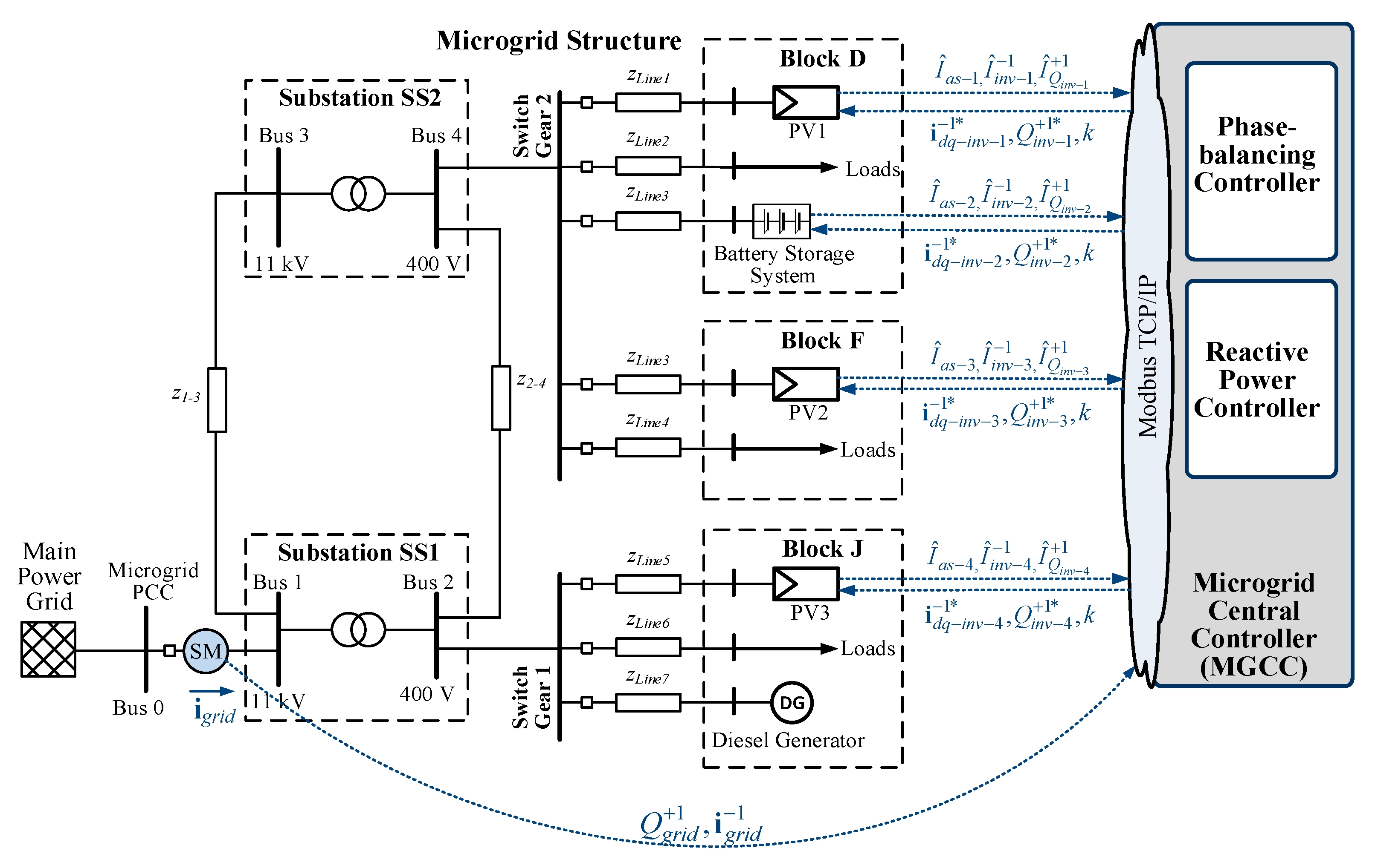
2. Microgrid Architecture
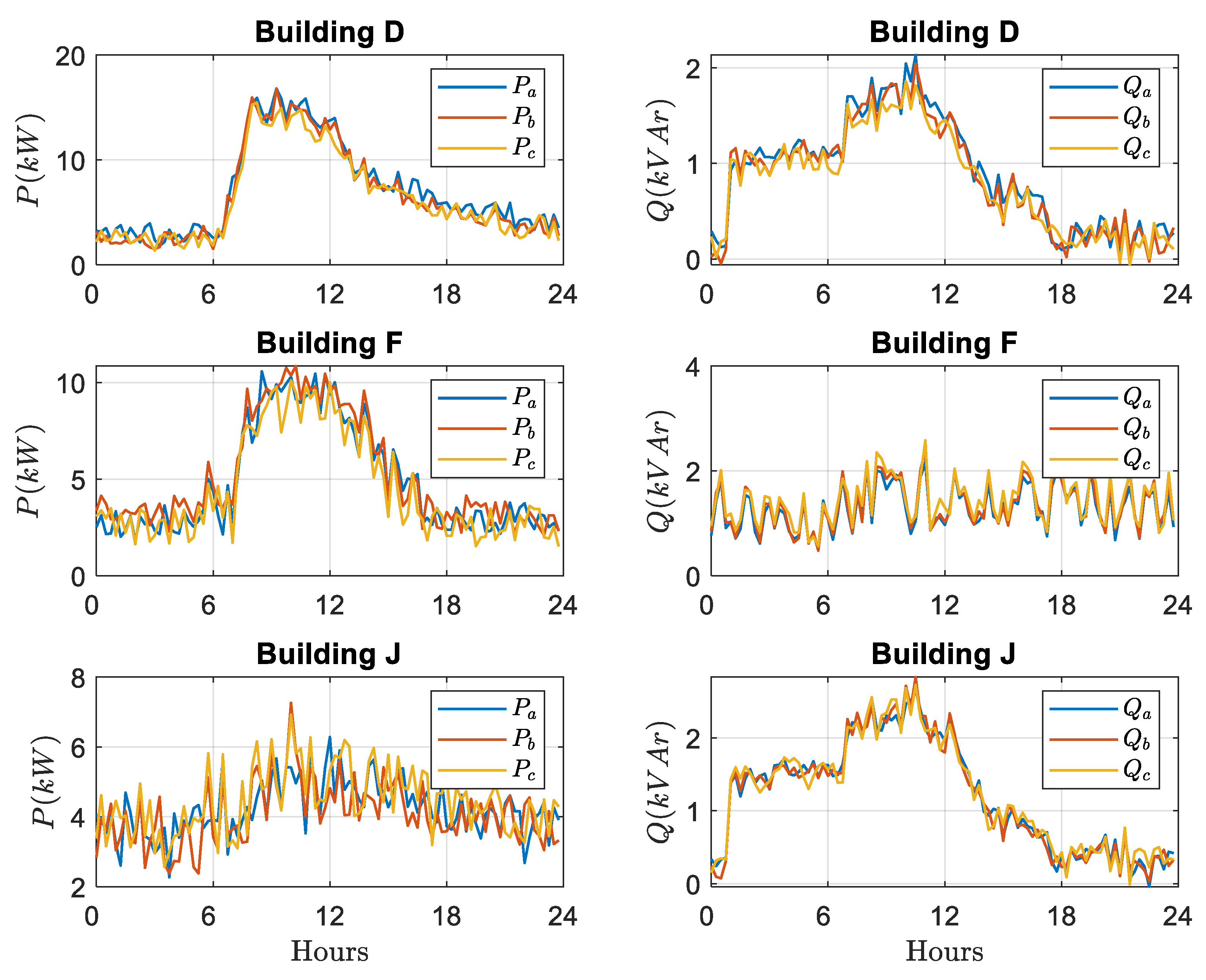
- Energy Demand
- B.
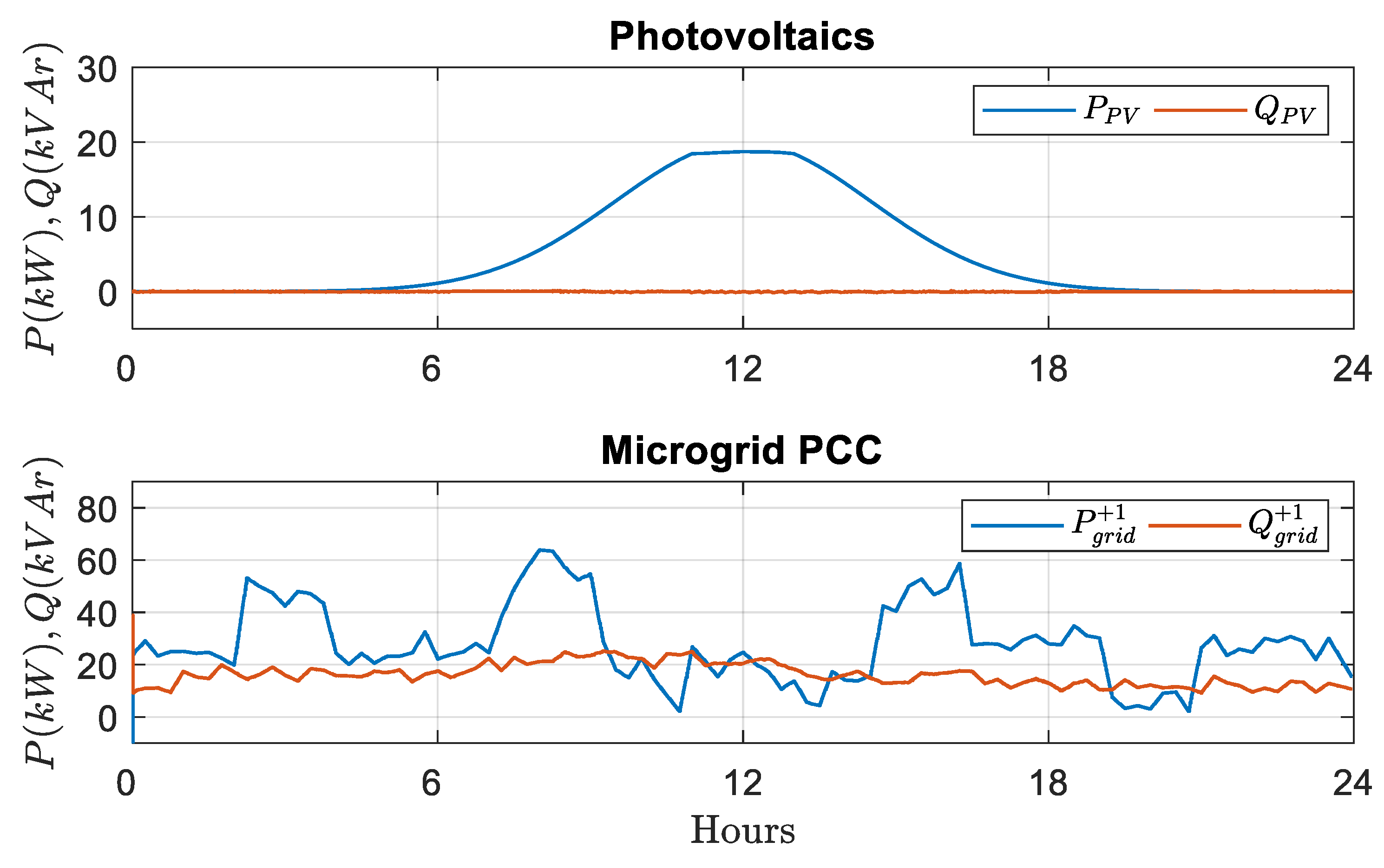
- Energy Generation
- C.
- Energy Storage
- D.
- Microgrid Central Controller (MGCC)
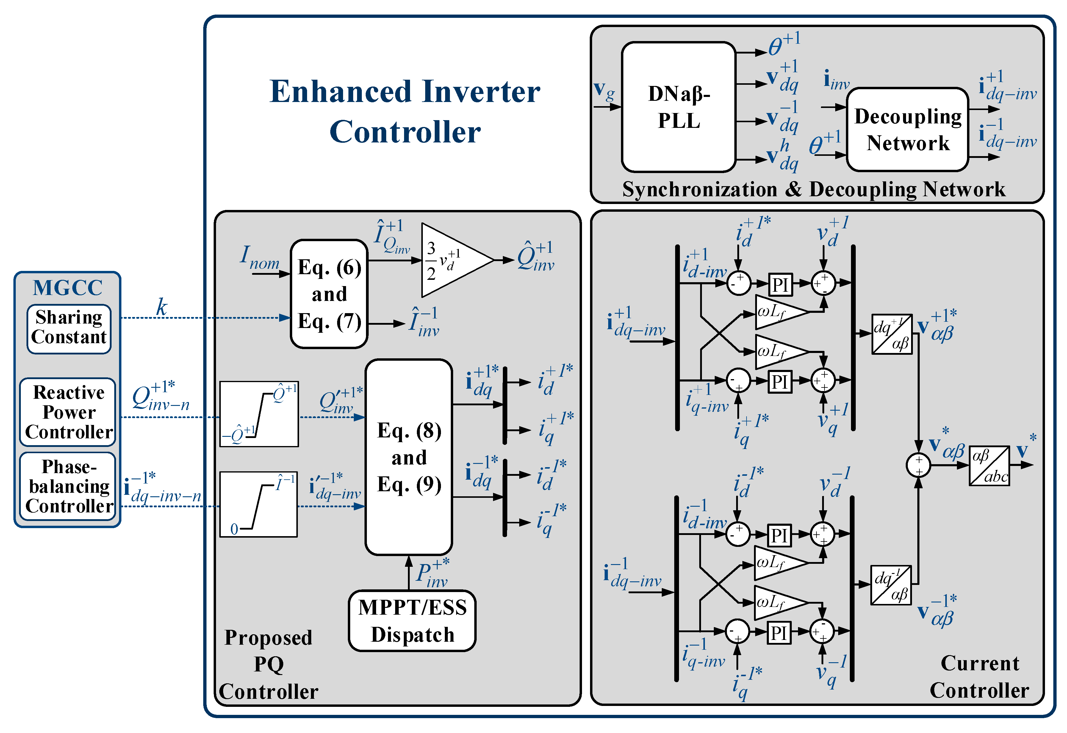
3. Advanced PV/ESS Controller
3.1. Proposed PQ Controller with Sharing Strategy for Ancillary Services
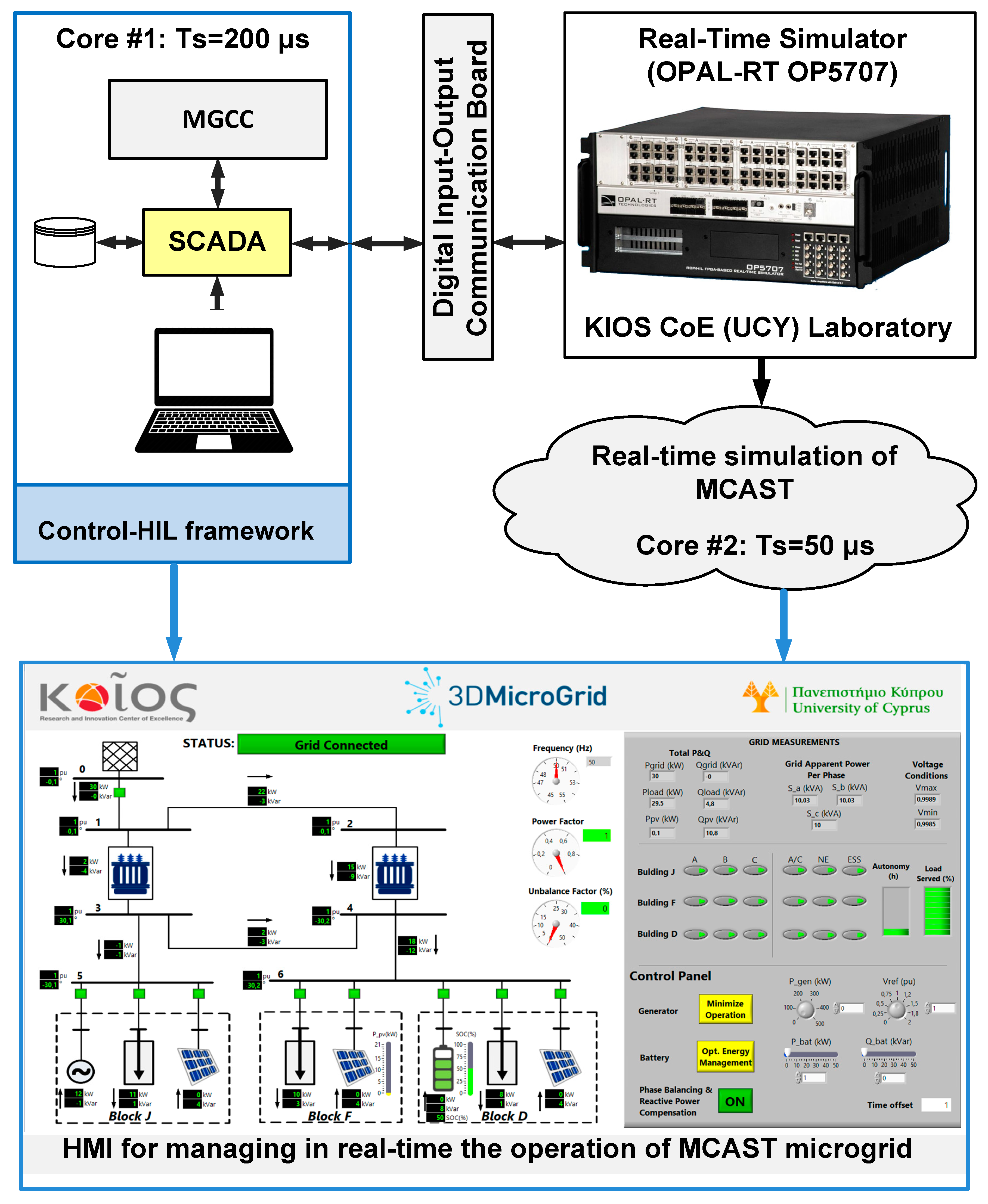
3.2. Experimental Setup
4. Microgrid Central Controller
4.1. Microgrid Central Controller (MGCC)
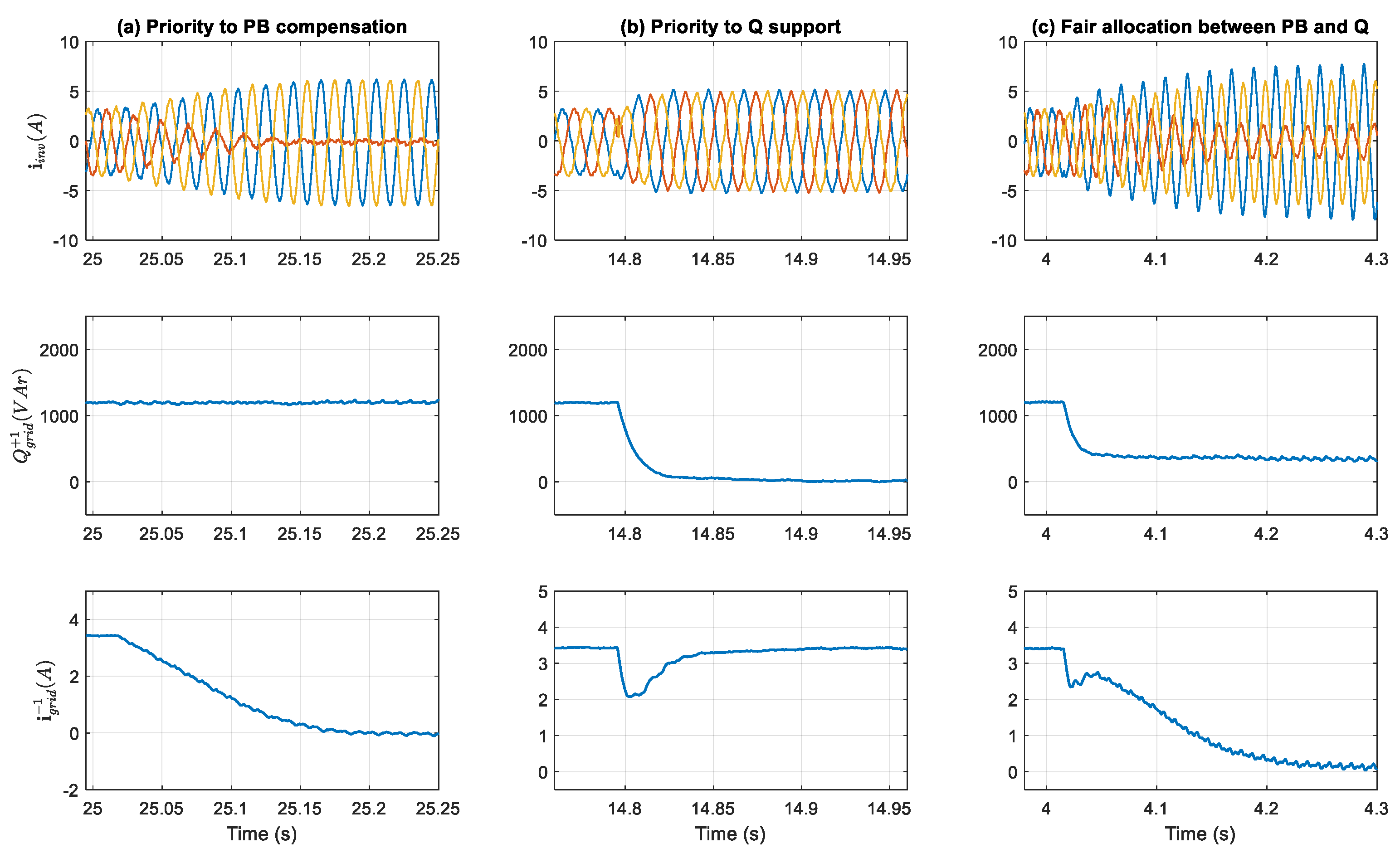
4.2. Real-Time Simulation-Base Scenario
4.3. Real Time Hardware In the Loop Investigation of the Proposed Solution
5. Conclusions
Author Contributions
Funding
Acknowledgments
Conflicts of Interest
References
- Guerrero, J.M.; Vasquez, J.C.; Matas, J.; de Vicuna, L.G.; Castilla, M. Hierarchical Control of Droop-Controlled AC and DC Microgrids—A General Approach Toward Standardization. IEEE Trans. Ind. Electron. 2011, 58, 158–172. [Google Scholar] [CrossRef]
- Heredero-Peris, D.; Chillón-Antón, C.; Pagès-Giménez, M.; Montesinos-Miracle, D.; Santamaría, M.; Rivas, D.; Aguado, M. An Enhancing Fault Current Limitation Hybrid Droop/V-f Control for Grid-Tied Four-Wire Inverters in AC Microgrids. Appl. Sci. 2018, 8, 1725. [Google Scholar] [CrossRef]
- Meng, L.; Savaghebi, M.; Andrade, F.; Vasquez, J.C.; Guerrero, J.M.; Graells, M. Microgrid Central Controller Development and Hierarchical Control Implementation in the Intelligent Microgrid Lab of Aalborg University. In Proceedings of the 2015 IEEE Applied Power Electronics Conference and Exposition (APEC), Charlotte, NC, USA, 15–19 March 2015; IEEE: Charlotte, NC, USA, 2015; pp. 2585–2592. [Google Scholar]
- Palizban, O.; Kauhaniemi, K. Hierarchical Control Structure in Microgrids with Distributed Generation: Island and Grid-Connected Mode. Renew. Sustain. Energy Rev. 2015, 44, 797–813. [Google Scholar] [CrossRef]
- Guerrero, J.M.; Chandorkar, M.; Lee, T.L.; Loh, P.C. Advanced Control Architectures for Intelligent Microgrids—Part I: Decentralized and Hierarchical Control. IEEE Trans. Ind. Electron. 2013, 60, 1254–1262. [Google Scholar] [CrossRef]
- Olivares, D.E.; Mehrizi-Sani, A.; Etemadi, A.H.; Canizares, C.A.; Iravani, R.; Kazerani, M.; Hajimiragha, A.H.; Gomis-Bellmunt, O.; Saeedifard, M.; Palma-Behnke, R.; et al. Trends in Microgrid Control. IEEE Trans. Smart Grid 2014, 5, 1905–1919. [Google Scholar] [CrossRef]
- Katiraei, F.; Iravani, M.R. Power Management Strategies for a Microgrid With Multiple Distributed Generation Units. IEEE Trans. Power Syst. 2006, 21, 1821–1831. [Google Scholar] [CrossRef]
- Tsikalakis, A.G.; Hatziargyriou, N.D. Centralized Control for Optimizing Microgrids Operation. In Proceedings of the 2011 IEEE Power and Energy Society General Meeting, Detroit, MI, USA, 24–29 July 2011; IEEE: San Diego, CA, USA, 2011; pp. 1–8. [Google Scholar]
- Zacharia, L.; Tziovani, L.; Savva, M.; Hadjidemetriou, L.; Kyriakides, E.; Bintoudi, A.D.; Tsolakis, A.; Martinez-Ramos, J.L.; Marano, A.; Azzopardi, B.; et al. Optimal Energy Management and Scheduling of a Microgrid in Grid-Connected and Islanded Modes. In Proceedings of the 2019 International Conference on Smart Energy Systems and Technologies (SEST), Porto, Portugal, 9–11 September 2019; IEEE: Porto, Portugal, 2019; pp. 1–6. [Google Scholar]
- IEEE Standard for the Specification of Microgrid Controllers; IEEE: New York, NY, USA, 2017.
- Sangwongwanich, A.; Yang, Y.; Blaabjerg, F. Development of Flexible Active Power Control Strategies for Grid-Connected Photovoltaic Inverters by Modifying MPPT Algorithms. In Proceedings of the 2017 IEEE 3rd International Future Energy Electronics Conference and ECCE Asia (IFEEC 2017—ECCE Asia), Kaohsiung, Taiwan, 3–7 June 2017; IEEE: Kaohsiung, Taiwan, 2017; pp. 87–92. [Google Scholar]
- Sangwongwanich, A.; Yang, Y.; Blaabjerg, F. High-Performance Constant Power Generation in Grid-Connected PV Systems. IEEE Trans. Power Electron. 2016, 31, 1822–1825. [Google Scholar] [CrossRef]
- SMA Solar Technology AG. Sunny Highpower Peak3. Available online: https://www.sma.de/ (accessed on 27 August 2019).
- Hadjidemetriou, L.; Kyriakides, E.; Blaabjerg, F.A. Robust Synchronization to Enhance the Power Quality of Renewable Energy Systems. IEEE Trans. Ind. Electron. 2015, 62, 4858–4868. [Google Scholar] [CrossRef]
- Hadjidemetriou, L.; Kyriakides, E. Accurate and Efficient Modelling of Grid Tied Inverters for Investigating Their Interaction with the Power Grid. In Proceedings of the 2017 IEEE Manchester PowerTech, Manchester, UK, 18–22 June 2017; IEEE: Manchester, UK, 2017; pp. 1–6. [Google Scholar]
- Ali, Z.; Christofides, N.; Hadjidemetriou, L.; Kyriakides, E. An Advanced Current Controller with Reduced Complexity and Improved Performance under Abnormal Grid Conditions. In Proceedings of the 2017 IEEE Manchester PowerTech, Manchester, UK, 18–22 June 2017; IEEE: Manchester, UK, 2017; pp. 1–6. [Google Scholar]
- Sangwongwanich, A.; Yang, Y.; Sera, D.; Soltani, H.; Blaabjerg, F. Analysis and Modeling of Interharmonics From Grid-Connected Photovoltaic Systems. IEEE Trans. Power Electron. 2018, 33, 8353–8364. [Google Scholar] [CrossRef]
- Reyes, M.; Rodriguez, P.; Vazquez, S.; Luna, A.; Teodorescu, R.; Carrasco, J.M. Enhanced Decoupled Double Synchronous Reference Frame Current Controller for Unbalanced Grid-Voltage Conditions. IEEE Trans. Power Electron. 2012, 27, 3934–3943. [Google Scholar] [CrossRef]
- Han, Y.; Li, H.; Shen, P.; Coelho EA, A.; Guerrero, J.M. Review of Active and Reactive Power Sharing Strategies in Hierarchical Controlled Microgrids. IEEE Trans. Power Electron. 2017, 32, 2427–2451. [Google Scholar] [CrossRef]
- Hadjidemetriou, L.; Zacharia, L.; Kyriakides, E.; Azzopardi, B.; Azzopardi, S.; Mikalauskiene, R.; Al-Agtash, S.; Al-hashem, M.; Tsolakis, A.; Ioannidis, D.; et al. Design Factors for Developing a University Campus Microgrid. In Proceedings of the 2018 IEEE International Energy Conference (ENERGYCON), Limassol, Cyprus, 3–7 June 2018; IEEE: Limassol, Cyprus, 2018; pp. 1–6. [Google Scholar]
- Parhizi, S.; Lotfi, H.; Khodaei, A.; Bahramirad, S. State of the Art in Research on Microgrids: A Review. IEEE Access 2015, 3, 890–925. [Google Scholar] [CrossRef]
- Hashempour, M.M.; Savaghebi, M.; Vasquez, J.C.; Guerrero, J.M. A Control Architecture to Coordinate Distributed Generators and Active Power Filters Coexisting in a Microgrid. IEEE Trans. Smart Grid 2016, 7, 2325–2336. [Google Scholar] [CrossRef]
- Kadam, S.; Bletterie, B. Balancing the Grid with Single-Phase PV-Installations. In Proceedings of the 2017 IEEE 26th International Symposium on Industrial Electronics (ISIE), Vancouver, BC, Canada, 19–21 June 2017; IEEE: Edinburgh, UK, 2017; pp. 63–69. [Google Scholar]
- Hadjidemetriou, L.; Zacharia, L.; Kyriakides, E. Flexible Power Control Scheme for Interconnected Photovoltaics to Benefit the Power Quality and the Network Losses of the Distribution Grid. In Proceedings of the 2017 IEEE 3rd International Future Energy Electronics Conference and ECCE Asia (IFEEC 2017—ECCE Asia), Kaohsiung Taiwan, 3–7 June 2017; IEEE: Kaohsiung, Taiwan, 2017; pp. 93–98. [Google Scholar]
- Ali, Z.; Christofides, N.; Hadjidemetriou, L.; Kyriakides, E. Multi-Functional Distributed Generation Control Scheme for Improving the Grid Power Quality. IET Power Electr. 2019, 12, 30–43. [Google Scholar] [CrossRef]
- Ali, Z.; Christofides, N.; Hadjidemetriou, L.; Kyriakides, E. Diversifying the Role of Distributed Generation Grid Side Converters for Improving the Power Quality of Distribution Networks Using Advanced Control Techniques. In Proceedings of the 2017 IEEE Energy Conversion Congress and Exposition (ECCE), Cincinnati, OH, USA, 1–5 October 2017; IEEE: Cincinnati, OH, USA, 2017; pp. 4786–4793. [Google Scholar]
- Najafi, F.; Hamzeh, M.; Fripp, M. Unbalanced Current Sharing Control in Islanded Low Voltage Microgrids. Energies 2018, 11, 2776. [Google Scholar] [CrossRef]
- Hadjidemetriou, L.; Charalambous, A.; Kyriakides, E. Control Scheme for Phase Balancing of Low-Voltage Distribution Grids. In Proceedings of the 2019 International Conference on Smart Energy Systems and Technologies (SEST), Porto, Portugal, 9–11 September 2019; IEEE: Porto, Portugal, 2019; pp. 1–6. [Google Scholar]
- Hadjidemetriou, L.; Charalambous, A.; Zacharia, L.; Kyriakides, E. A Sensor-less Control Scheme for Grid Tied Inverters to Provide Phase Balancing Services to the Distribution Grid. In Proceedings of the EPE’19 ECCE Europe, Genova, Italy, 2–6 September 2019; IEEE: Genova, Italy, 2019; pp. 1–6. [Google Scholar]
- Savaghebi, M.; Jalilian, A.; Vasquez, J.C.; Guerrero, J.M. Secondary Control Scheme for Voltage Unbalance Compensation in an Islanded Droop-Controlled Microgrid. IEEE Trans. Smart Grid 2012, 3, 797–807. [Google Scholar] [CrossRef]
- Savaghebi, M.; Jalilian, A.; Vasquez, J.C.; Guerrero, J.M. Secondary Control for Voltage Quality Enhancement in Microgrids. IEEE Trans. Smart Grid 2012, 3, 1893–1902. [Google Scholar] [CrossRef]
- Zacharia, L.; Kyriakou, A.; Hadjidemetriou, L.; Kyriakides, E.; Panayiotou, B.; Azzopardi, C.; Martensen, N.; Borg, N. Islanding and Resynchronization Procedure of a University Campus Microgrid. In Proceedings of the 2018 International Conference on Smart Energy Systems and Technologies (SEST), Sevilla, Spain, 10–12 September 2018; IEEE: Sevilla, Spain, 2018; pp. 1–6. [Google Scholar]
- Janitza Electronics. UMG 604-E PRO. Available online: https://www.janitza.com (accessed on 27 August 2019).
- Olaszi, B.D.; Ladanyi, J. Comparison of Different Discharge Strategies of Grid-Connected Residential PV Systems with Energy Storage in Perspective of Optimal Battery Energy Storage System Sizing. Renew. Sustain. Energy Rev. 2017, 75, 710–718. [Google Scholar] [CrossRef]


| Switching and sampling frequency | 3.45 kHz |
| Synchronization Unit | DNαβ-PLL (kP = 92, Ti = 0.000235) |
| Current Controller | kP = 17.3, kI = 218.5 |
| LC Filter | Rif = 0.19 Ω, Lif = 15 mH, Cif = 9.45 μF |
| Additional Inductance | Zg1 = 4.7 mH |
© 2019 by the authors. Licensee MDPI, Basel, Switzerland. This article is an open access article distributed under the terms and conditions of the Creative Commons Attribution (CC BY) license (http://creativecommons.org/licenses/by/4.0/).
Share and Cite
Charalambous, A.; Hadjidemetriou, L.; Zacharia, L.; Bintoudi, A.D.; Tsolakis, A.C.; Tzovaras, D.; Kyriakides, E. Phase Balancing and Reactive Power Support Services for Microgrids. Appl. Sci. 2019, 9, 5067. https://doi.org/10.3390/app9235067
Charalambous A, Hadjidemetriou L, Zacharia L, Bintoudi AD, Tsolakis AC, Tzovaras D, Kyriakides E. Phase Balancing and Reactive Power Support Services for Microgrids. Applied Sciences. 2019; 9(23):5067. https://doi.org/10.3390/app9235067
Chicago/Turabian StyleCharalambous, Anastasis, Lenos Hadjidemetriou, Lazaros Zacharia, Angelina D. Bintoudi, Apostolos C. Tsolakis, Dimitrios Tzovaras, and Elias Kyriakides. 2019. "Phase Balancing and Reactive Power Support Services for Microgrids" Applied Sciences 9, no. 23: 5067. https://doi.org/10.3390/app9235067