Abstract
The profile accuracy of screw rotors plays a vital role in stabilizing the meshing operation between mated rotors. Such stability can minimize the vibration and noise, as well as improve the sealing performance and wear resistance. This is the main reason why form grinding is extensively applied as a finishing process to maintain high screw rotor profile accuracy. Since the installation parameters for form grinding wheels affect both the grinding wheel profile accuracy and grinding performance, it is essential to obtain reasonable installation parameters to guarantee the high precision and good grinding performance of form grinding wheels. In this paper, a novel optimization design method for form grinding wheels for screw rotors has been proposed. For the first time, the relationship between the grinding wheel installation parameters and profile accuracy is established to evaluate the grinding performance. A parameterized program has been designed based on space engagement theory. The characteristics of the contact line and profile features of form grinding wheels under different installation parameters have been investigated. Then, the proposed method was employed to select the correct range of installation parameters. To validate the proposed method, a set of experiments, including the manufacture and measurement of several screw rotors, was carried out. The results reveal that the precision of the screw profile is significantly improved compared with the empirical method, thus showing the effectiveness of the proposed method.
1. Introduction
Screw rotors are extensively used in positive displacement screw machines such as compressors, vacuum pumps, etc. [1]. As the major functionality part of such machines, the profile accuracy is often the decisive factor of the machine’s performance. Low profile accuracy often downgrades the screw machine’s sealing performance, vulnerates the rotors to wear, and causes undesired noise and detrimental vibration. As such, precision form grinding has been widely used in screw rotor factories due to its high finishing accuracy. The installation parameters of the form grinding wheel can directly determine the accuracy of the grinding wheel profile; they also have significant effects on the grinding performance of the form wheel grinding. Thus, it has become increasingly important to reasonably and scientifically select appropriate installation parameters and to be able to rapidly obtain wheel profiles with good grinding performance. Installation parameters are usually determined by the empirical approach, which may lead to a low profile accuracy and poor grinding performance of the form grinding wheel, which in turn will affect the precision of the screw rotor. In order to produce a screw rotor with high profile precision, it is essential to optimally design the profile of the form grinding wheel through its installation parameter settings.
Both the design principle of the screw rotor form tool and the theoretical mathematical modeling of the tool profile design have been extensively studied in the existing literature. Litvin and Fuentes [2] extended an enveloping method to gear design and manufacture. Subsequently, Wu [3] advanced the design principle by figuring out the governing equation describing the contact status between the form tool and screw rotor. Mimmi et al. [4] proposed a method to determine the theoretical shape of the disk cutter for a screw pump rotor. Shreehah and Abdullah [5] demonstrated a new method of grinding process that could efficiently make the concave profile of the worm thread smooth. These studies reviewed the methods used in the design of screw rotor form tools in detail, but they did not discuss the selection methods for the installation parameters. In another sense, these works also provided some reference for follow-up studies of the design of the form tool for screw rotors. For example, Radzevich et al. [6,7] proposed a method to determine the grinding wheel profile and its setup for use in finishing cylindrical gears with an evolvent profile by using the meshing principle and enveloping theory. Wu et al. [8], who proposed a radial-ray shooting (RRS) method to simulate the form grinding process for screw rotors, obtained an accurate simulation profile for screw rotors. Based on discrete point teeth and the gear meshing principle under stable-contact conditions, Tang et al. [9] proposed a form-position geometric method. With the proposed method, the precise design of a cutter at the cusp of the screw profile could be solved. Further, a novel calculation method was proposed by Li [10], who calculated the wheel profile using a predetermined groove model and wheel axis setting parameters. While these studies have provided valuable information about the design principles used in form tools, they have not reported on the effect of installation parameters on the profile error in the process of form grinding.
In contrast, extensive studies have reported on the profile accuracy (or error) of screw rotors. For example, Stosic [11] calculated the tool wear amount of a milling cutter in screw rotor machinery and estimated errors using a tool–rotor transformation method. In this method, the relative movements of the tool and screw rotor were taken into consideration, since different movements would lead to different tool wear. To investigate the influence of grinding wheel installation on the rotor profile, a numerical method considering various installation errors (e.g., installation angle error, center distance error, and axial position error) was presented by Tao et al. [12]. Using the computer numerical control (CNC) method, Zhao et al. [13] investigated the precision grinding via an analysis of the major grinding parameters (e.g., center distance, swivel angle, and initial phase angle) and screw rotor profile. The authors managed to improve the screw rotor profile accuracy with a novel grinding wheel segmentation dressing method. Grinding experiments successfully verified the correctness of the results evaluated by this method.
Recent research on spiral bevels and screw surfaces has examined the influence of machine settings and installation parameters on machining errors, and several authors have proposed error compensation methods [14,15,16]. These researchers have attempted to control the installation parameters such that the target for improving machining accuracy could be reached. These models can improve the profile accuracy in screw surface machining to some extent; unfortunately, these studies have examined the influence of installation parameters on profile errors with the assumption that the wheel profile is known. The selection method of installation parameters is not involved in the form tool design stage. A novel tilt form grinding method was presented by Zhang and Fong [17] to address the difficulties in concave profile grinding. By using their proposed machine arrangement and installation parameters, a concave rotor profile can be ground without undercutting or secondary enveloping. Deng and Shu [18] used envelope theory to design a screw rotor cutter by including an installation parameter design method. However, it can only be used to select the installation parameters regarding the polylines of the rotor profile; in addition, they did not report on the selection method that they used for the installation parameters for smooth curves. Regrettably, none of these methods can be used to determine the installation parameters for the form cutter for smooth screw profiles. The use of improper installation parameters will reduce the profile precision and grinding performance of the form cutter, and the machining precision of the screw rotor will also suffer.
In industrial applications, the screw rotor profile is usually a smooth curve consisting of data points from either design software or measurements. Therefore, it is essential to obtain the correct installation parameters according to these discrete data. In this way, the high precision and good grinding performance of the form grinding wheel can be addressed. In this paper, a novel optimization design method of installation parameters has been proposed. With this method, the dressing and grinding performance of the grinding wheel can be predicted during the design stage, such that improvements in machining accuracy and screw rotor efficiency may be achieved.
The remainder of this paper is organized as follows. First, the form cutter design method and the form grinding principle are introduced, which together provide a basis for the subsequent procedures. Then, a parameterized program is designed based on space engagement theory and the coordinate transformation between the screw rotor and the grinding wheel. Subsequently, the characteristics of the contact line and profile features of wheel grinding under different installation parameters are investigated, providing basis for the selection of installation parameters. Finally, grinding experiments are conducted on a profile grinding machine; then, the experimental data are analyzed by comparing them with the theoretical results to demonstrate the effectiveness of the proposed method.
2. Theoretical Background
2.1. The Coordinate Relationship between the Screw Rotor and the Grinding Wheel
In order to obtain precise installation parameters, the coordinate transformation and meshing relationship between the screw rotor and the grinding wheel needs to be established according to grinding space geometry and engagement theory. Given that the cross-section of the screw rotor is composed of multiple discrete points (), as shown in Figure 1, the helical surface equation can be expressed as follows [3]:
where p is the screw parameter of the rotor, and p = S/2π (S is the lead of the screw rotor).
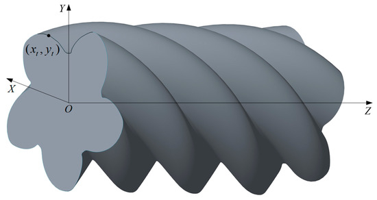
Figure 1.
Three-dimensional (3D) structure of the screw rotor.
Noting that the grinding wheel shaft is mathematically described by multiple discrete points (), as shown in Figure 2, the revolution surface equation of the grinding wheel can be expressed as follows [3]:
where , , and are the revolution surface equation of the grinding wheel; is the radius when the width of the grinding wheel is ; is the angle between and the plane; and the to direction is defined as the positive direction.
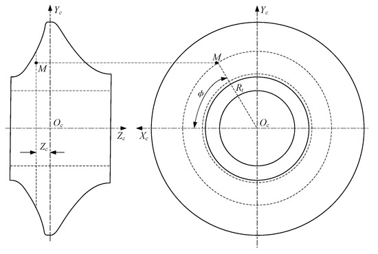
Figure 2.
Schematic diagram of the grinding wheel structure.
The screw surface is formed by relative meshing movement enabled by the grinding wheel and the screw rotor. Figure 3 shows the geometric relationship between a grinding wheel and a screw rotor. The mounting angle is formed due to the crossing axes of the grinding wheel and the screw rotor. The distance between the axes and a point on the contact line is denoted by and , respectively. represents the screw rotor coordinate system, while represents the grinding wheel coordinate system.
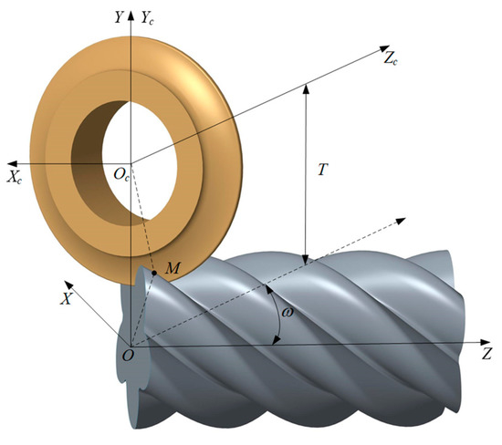
Figure 3.
Coordinate systems of the grinding wheel and the screw rotor.
The geometric relationship between the grinding wheel coordinate system and the screw rotor coordinate system is as follows:
where , , is the unit vector in the grinding wheel coordinate system , and , , and are the unit vectors in the screw rotor coordinate system .
2.2. Form Wheel Profile Generation Model
Once the screw rotor profile is known, the profile of the form wheel can be derived. The contact line equation can be expressed as [3]:
where is the radial vector of in , and is the normal vector at . The component of the normal vector at three coordinate axes can be calculated based on the following equation:
Substituting and in Equation (1) with their corresponding partial derivative, the following relationship can be obtained:
Substituting Equations (9) and (10) into Equation (8) yields the following:
The substitution of Equations (5) and (7) into Equation (7) then yields:
where is the first-order derivative of versus , which can be obtained by MATLAB (The MathWorks, Inc., Natick, MA, USA). As can be seen from the above equations, the only unknown variable can be calculated using . Therefore, both the contact line and grinding wheel profile can be solved.
2.3. Rotor Profile Generation Model
The profile of the screw rotor can be derived once the form wheel profile is known. The contact line equation can be expressed as [3]:
where is the radial vector of in . In the screw rotor coordinate system , the vector can be expressed as follows:
Substituting Equation (6) into Equation (14), in the screw rotor coordinate system , the vector can be expressed as:
The term can be calculated as follows:
The normal vector at each coordinate axis can be figured out according to:
Taking the partial derivative of and , the following relationship can be obtained:
Substituting Equations (18) and (19) into Equation (17) yields the following:
Then, the substitution of Equations (16) and (20) into Equation (13) yields:
where is the first-order derivative of versus . Since each can be used to deduce two different values of , the value can be regarded as a function of , as shown in Figure 2. The term is provided by the inverse function theorem:
On the one hand, it can be observed from Equation (21) that angle is the only variable to be determined; on the other hand, it is worth noticing that can be used to determine angle . As such, the space contact line can be figured out, based on which the screw rotor profile can also be determined.
2.4. Calculation Method of Profile Errors
The rotor profile errors must be defined reasonably and scientifically; they must also be easily measurable in order to evaluate the profile errors of the screw rotor. Figure 4 shows the profile of the compressor rotor. In Figure 5, the rotor profile errors are calculated according to the machined profile and the theoretical profile. is a point on and it is represented by ().
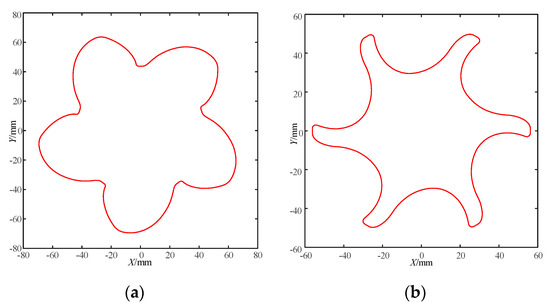
Figure 4.
Theoretical rotor profiles. (a) Male rotor. (b) Female rotor.
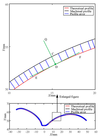
Figure 5.
The profile error of the screw rotor cross-section.
To facilitate the calculation, the cubic parametric curve is selected to characterize the theoretical rotor profile:
A point on is denoted by and is represented by () (), where is the number of measured profile data points. The profile error is defined as the shortest distance between and the theoretical profile. is positive when is outside the theoretical profile, and vice versa, and it can be calculated using the following equation:
where points () satisfy Equation (23). The sign in Equation (24) is chosen based on the relationship of the machined rotor profile and the theoretical rotor profile. Specifically, if , ‘‘+’’ is chosen; otherwise, ‘‘−’’ is chosen. The shortest distance, , can be easily determined using the numeric method, and the profile error can then be determined.
3. Installation Parameter Optimization Design Method
In precision form grinding, the grinding wheel installation parameters have significant influence on the screw rotors’ profile accuracy. Section 2 showed the coordinate relationship between the screw rotor and the grinding wheel, and the calculation method for determining rotor profile errors. Due to the importance of the installation parameters, it is essential to study the selection method for precise installation parameters. This paper contains a novel optimization design method for the installation parameters based on space engagement theory and the coordinate transformation between the screw rotor and the grinding wheel.
3.1. Installation Angle Optimization Design Method
In order to obtain a precise installation angle, the optimal design procedures of the installation angle are designed as shown in Figure 6. In industrial applications, the diameter of the form grinding wheel usually becomes increasingly smaller with an increased grinding time. In order to make full use of the whole grinding wheel, the minimum installation center distance can be used as the initial center distance. The installation angle is usually the value near the lead angle (pitch circle) of the screw rotor. In this study, the best installation angle was found within ±5° away from the lead angle. A female screw rotor is used as an example in Table 1.
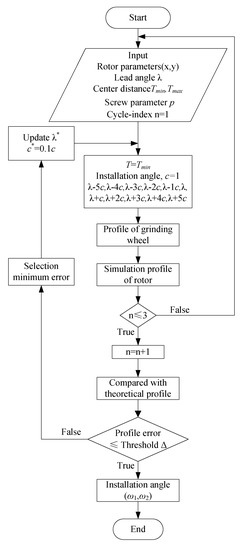
Figure 6.
Installation angle optimization design method.

Table 1.
Basic parameters of a female rotor.
The steps involved in the optimized design procedure are described as follows:
Step 1. Obtain the parameter inputs, including rotor profile parameters, lead angle, center distance, screw parameter, and cycle index.
Step 2. Preprocess the input parameters.
Step 3. Obtain the profile of the grinding wheel.
Step 4. Obtain the simulation profile of the screw rotor.
Step 5. If the cycle index n ≤ 3, then perform the next step; otherwise, return to Step 1.
Step 6. Evaluate the profile error between the simulation profile and the theoretical profile. Once the profile error ≤ threshold , record the installation angle; otherwise, return to Step 2 and continue to search for the installation angle.
During the calculation of the first cycle, the installation angle is searched in the interval () that satisfies the condition . Through the calculation of three cycles, the precise installation angle range can be obtained.
3.2. Center Distance Optimization Design Method
Similarly, in order to obtain the range of the center distance, the optimal design procedures of the center distance are designed as shown in Figure 7. In industrial applications, the installation center distance is usually not strictly required; it normally depends on the process parameters of the machine tool and the structure parameters of the tool, and the center distance can be searched in the interval (), in which and are the maximum and minimum center distance allowed by the machine tool and tool rest structure, respectively.
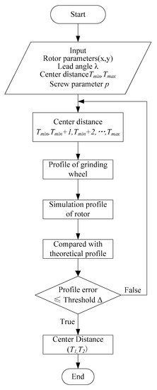
Figure 7.
Center distance optimization design method.
The steps involved in the optimized design procedure are as follows:
Step 1. Obtain the parameter inputs, including the rotor profile parameters, lead angle, center distance, and screw parameter.
Step 2. Preprocess the input parameters.
Step 3. Obtain the profile of the grinding wheel.
Step 4. Obtain the simulation profile of the screw rotor.
Step 5. Evaluate the profile error between the simulation and theoretical profiles. Once the maximum profile error , record the center distance; otherwise, return to Step 2 and continue to search for the center distance.
The installation angle and the center distance can be optimally designed before the grinding process begins. The installation parameters of the female screw rotor during grinding are shown in Figure 8.
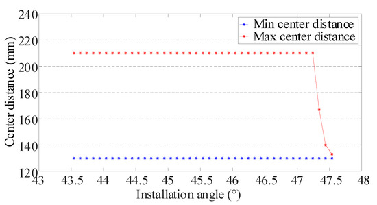
Figure 8.
Installation parameters of the female screw rotor.
3.3. Profile Analysis of Form Wheel Grinding
In order to obtain the best installation parameters within the range of requirements, the characteristics of the contact line and the profile features of wheel grinding under different installation parameters need to be investigated. The lengths of the contact line under different installation parameters are shown in Table 2.
Table 2.
Length of contact lines under different installation parameters.
Table 2 shows the length values of the contact lines under different installation parameters. When the installation angle remains unchanged, the length of the contact line increases with the increased center distance, and vice versa. In contrast, the length of the contact line decreases as the installation angle increases under the condition in which the center distance stays constant, and vice versa. According to the grinding mechanism, it is well known that the longer the contact line, the better the heat dissipation during the grinding process. Thus, long contact lines are conducive to improving the grinding quality of the screw rotor.
In order to evaluate the profile features of wheel grinding under different installation parameters, the slope and curvature of the cross-section profile of the grinding wheel were determined, as shown in Figure 9. When the center distance remains unchanged, the slope and curvature of the shaft section profile of the grinding wheel both increase with the increase in the installation angle, and vice versa. In contrast, the slope and curvature of the shaft section profile of the grinding wheel decrease as the center distance increases in the condition in which the installation angle stays constant, and vice versa. The smaller the slope and curvature, the smoother the shaft section profile of the grinding wheel and the easier it is to dress the grinding wheel. In addition, the smoother the profile, the better the wear resistance of the grinding wheel. During the actual grinding process, the radius of the grinding wheel is usually reduced from large to small, and the center distance becomes increasingly smaller. Therefore, the installation angle must be controlled as a priority.
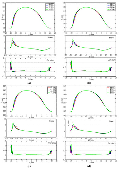
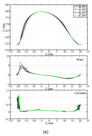
Figure 9.
Profile features of wheel grinding under different installation parameters. (a) Center distance, 129.45 mm. (b) Center distance, 149.45 mm. (c) Center distance, 169.45 mm. (d) Center distance, 189.45 mm. (e) Center distance, 209.45 mm.
In summary, through the above profile analysis of wheel grinding, some conclusions can be drawn as follows. Different installation parameters correspond to different contact line lengths; the slope and curvature of the shaft section profile of the grinding wheel also vary with the installation parameters. The installation angle should be properly selected to ensure the good dressing and grinding performance of the form grinding wheel. When these situations are considered holistically, a small installation angle should be selected under the condition where the meshing relationship between the screw rotor and the form grinding wheel is satisfied.
4. Experiment and Results
4.1. Experimental Setup
In order to verify the above effects of the installation parameters of the grinding wheel on the rotor profile, a set of screw rotor grinding experiments were conducted on an SU G500H profile grinding machine (Star SU, Farmington Hills, MI, USA) using an alumina grinding wheel (NORTON-3NQ60-H12VSP) (NORTON, Shanghai, China). The screw rotor used was a QT500 (HB 170–210). A Variocut G600HC (Castrol, Taicang, China) was used as the cutting fluid in the grinding process. In current production practice, the installation angle is usually equivalent to the lead angle . The geometric parameters of the screw rotor were shown earlier, in Table 1; Table 3 shows the experimental installation parameters. The female rotor was ground as shown in Figure 10. Figure 11 shows the machined profile measurement setup with a fully automatic CNC-controlled P26 precision measuring center.
Table 3.
Installation parameters.
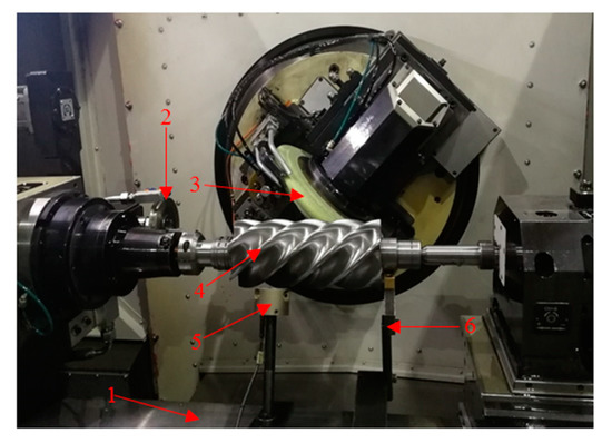
Figure 10.
Grinding experimental setup. 1. Worktable, 2. Diamond dressing wheel, 3. Grinding wheel, 4. Screw rotor, 5. Location sensor, 6. Auxiliary support.
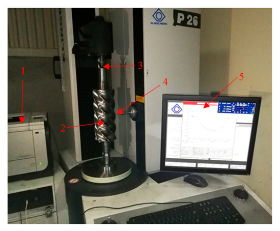
Figure 11.
Fully automatic computer numerical control (CNC)-controlled P26 precision measuring center. 1. Printing mechanism 2. Clamping device 3. Screw rotor. 4. Measuring head 5. Display instrument.
The distribution of abrasive grains on the surface of the grinding wheel is too complicated to analyze directly. Here, in order to facilitate the research, the following assumptions are made to simplify the surface of the grinding wheel:
- The grinding wheel was dressed well before every grinding pass by the diamond wheel.
- The abrasive grains have the same protrusion height and are evenly distributed on the grinding wheel surface.
A set of screw rotor grinding experiments was conducted to verify the proposed method. The installation parameters for the screw rotor in the form grinding process, including the installation angle and the center distance, are listed in Table 3. Based on the screw rotor data (), the screw surface can be determined; furthermore, the form grinding wheel can be dressed under the conditions of the given installation parameters. After grinding experiments were carried out under the given conditions, the profile error could be calculated according to the method mentioned in Section 2.
4.2. Results and Discussion
Since the grinding wheel wear is unavoidable during the grinding process, the machined profile can be measured in the middle of the screw surface (see Figure 11) to obtain precise comparison results. The results of the four experiments are shown in Figure 12, together with comparisons between the machined and theoretical profiles. The following observations are worth noting from Figure 12:
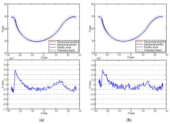
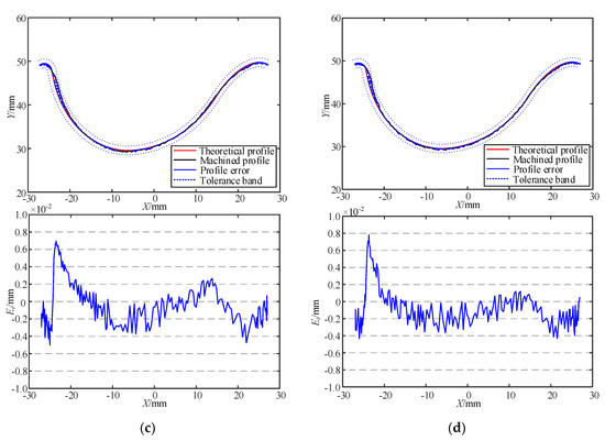
Figure 12.
The effects of the installation angle on screw rotor profiles (mm). (a) Installation angle, 44.09°. (b) Installation angle, 45.09°. (c) Installation angle, 46.09°. (d) Installation angle, 47.09°.
- In Experiments 1 through 4, the profile errors became increasingly large; the maximum profile error increased from ±6 μm to ±8 μm.
- The areas with larger profile errors of the screw rotor corresponded to areas with a larger profile slope and curvature of the grinding wheel.
- The results from Experiments 1 through 4 also showed that the surface integrity increasingly worsened, because the small length of the contact line leads to poor heat dissipation.
Using the empirical method, the profile error is large when the installation angle is equal to the lead angle. Grinding wheels are more prone to wear when the slope and curvature of the shaft section profile of the grinding wheel are large. In addition, the longer the contact line, the better the grinding surface integrity. Based on the above findings, it can be found that the profile error is significantly reduced compared with the empirical method during the grinding process of a female rotor, which indicates that the proposed optimization design method can provide better grinding performance for form grinding wheels used with screw rotors than is possible when using the empirical method. To the best of the authors’ knowledge, this is the first time that the grinding performance of the grinding wheel is related to the installation parameters, and the grinding performance of the grinding wheel is optimized in the design stage.
5. Conclusions
This paper proposed a novel optimization design method of form wheels that considers installation parameters. This method has been employed to select the correct range for the installation angle and center distance. According to coordinate transformation and engagement theory, a profile generation model was established, based on which numerical simulation was subsequently carried out. The numerical cases show that the slope and curvature of the grinding wheel shaft profile as well as the length of contact line will change with the installation parameters. Grinding experiments for a female rotor by introducing different installation parameters were performed in order to verify the results of the numerical cases. Several important conclusions are drawn from this work, as follows:
- (1)
- The installation parameter optimization design model was established based on geometric transformation and engagement theory. The ranges of the installation angle and center distance satisfying meshing conditions were obtained.
- (2)
- The characteristics of the contact line and the profile features of the wheel grinding under different installation parameters were investigated. The numerical relationship between the slope and curvature of the shaft section profile of the grinding wheel, as well as the length of the contact line and the installation parameters have been clarified. Error-sensitive factors were also identified. The installation angle is a relatively sensitive factor that must be controlled in priority.
- (3)
- The evaluation criteria for the profile characteristics of the grinding wheel were established, and female rotor grinding experiments were conducted. The new installation angle was compared with the empirical approach (lead angle), and the profile precision was found to have increased from ±8 μm to ±6 μm.
The above conclusions show that the proposed optimization design method is accurate and reliable for selecting the precision installation parameters for a certain twin screw compressor’s profile. Previously, there was no applicable method and theory for selecting the installation parameters of the forming tool in the process of screw rotor manufacture, which leads to the difficulty in improving the machining accuracy. In this paper, the internal relationship between the grinding performance of a forming wheel and its installation parameters is studied for the first time, and an optimization design method of installation parameters is proposed. This paper also provides a new viewpoint for the selection of installation parameters for form tools used in form machining. In future work, the optimization design method could also be extended to other types of form machining. Practical optimization design software for this approach could also be developed to improve the efficiency of precision design of form grinding wheels.
Author Contributions
Conceptualization, Z.L.; Data curation, Z.L.; Funding acquisition, Q.T.; Investigation, N.L.; Project administration, Q.T.; Validation, P.H.L. and W.L.
Funding
This work was financially supported by The National Key Research and Development Program of China (grant number 2018YFB1701203), the National Natural Science Foundation of China (grant number 51575069), the Doctoral Funding of Chongqing University of Chongqing Technology and Business University (grant number 1956029), The opening project of the international joint research center for health care in service of china-canada equipment system (grant number KFJJ2019061).
Conflicts of Interest
The authors declare no conflict of interest.
References
- Kovacevic, A.; Stosic, N.; Mujic, E.; Smith, I.K. CFD integrated design of screw compressors. Eng. Appl. Comput. Fluid Mech. 2007, 1, 96–108. [Google Scholar] [CrossRef][Green Version]
- Litvin, F.L.; Fuentes, A. Gear Geometry and Applied Theory; Cambridge University Press: Cambridge, UK, 2004. [Google Scholar]
- Wu, X. Theory of Gearing; Xi’an Jiaotong University Press: Xi’an, China, 2009. (In Chinese) [Google Scholar]
- Mimmi, G.; Pennacchi, P. Determination of tool profile for the milling of three-screw pump rotor. Meccanica 1997, 32, 363–377. [Google Scholar] [CrossRef]
- Abu Shreehah, T.A.; Abdullah, R.A. Modification of geometry and technology of cylindrical worms. Mach. Sci. Technol. 2006, 10, 539–547. [Google Scholar] [CrossRef]
- Radzevich, S.P. Computation of parameters of a form grinding wheel for grinding of shaving cutter for plunge shaving of topologically modified involute pinion. J. Manuf. Sci. Eng. 2005, 127, 819–828. [Google Scholar] [CrossRef]
- Radzevich, S.P.; Krehe, R. Determination of the grinding wheel profile and its setup for use in finishing cylindrical gears with an evolvent profile. Int. J. Adv. Manuf. Technol. 2012, 63, 875–879. [Google Scholar] [CrossRef]
- Wu, Y.R.; Fong, Z.H.; Zhang, Z.X. Simulation of a cylindrical form grinding process by the radial-ray shooting (RRS) method. Mech. Mach. Theory. 2010, 45, 261–272. [Google Scholar] [CrossRef]
- Tang, Q.; Zhang, Y.; Jiang, Z.; Yan, D. Design method for screw form cutter based on tooth profile composed of discrete points. J. Mech. Des. 2015, 137, 085002. [Google Scholar] [CrossRef]
- Li, G. A new algorithm to solve the grinding wheel profile for end mill groove machining. Int. J. Adv. Manuf. Technol. 2017, 90, 775–784. [Google Scholar] [CrossRef]
- Stosic, N. Evaluating errors in screw rotor machining by tool to rotor transformation. Proc. Inst. Mech. Eng. Part B J. Eng. Manuf. 2006, 220, 1589–1596. [Google Scholar] [CrossRef]
- Tao, L.; Wang, Y.; He, Y.; Feng, H.; Ou, Y.; Wang, X. A numerical method for evaluating effects of installation errors of grinding wheel on rotor profile in screw rotor grinding. Proc. Inst. Mech. Eng. Part B J. Eng. Manuf. 2016, 230, 1381–1398. [Google Scholar] [CrossRef]
- Zhao, Y.; Zhao, S.; Wei, W.; Hou, H. Precision grinding of screw rotors using CNC method. Int. J. Adv. Manuf. Technol. 2017, 89, 2967–2979. [Google Scholar] [CrossRef]
- Xiang, S.; Li, H.; Deng, M.; Yang, J. Geometric error analysis and compensation for multi-axis spiral bevel gears milling machine. Mech. Mach. Theory. 2018, 121, 59–74. [Google Scholar] [CrossRef]
- Ding, H.; Tang, J.; Zhong, J. Accurate nonlinear modeling and computing of grinding machine settings modification considering spatial geometric errors for hypoid gears. Mech. Mach. Theory. 2016, 99, 155–175. [Google Scholar] [CrossRef]
- Shih, Y.-P.; Chen, S.-D. A flank correction methodology for a five-axis CNC gear profile grinding machine. Mech. Mach. Theory. 2012, 47, 31–45. [Google Scholar] [CrossRef]
- Zhang, Z.-X.; Fong, Z.-H. A novel tilt form grinding method for the rotor of dry vacuum pump. Mech. Mach. Theory. 2015, 90, 47–58. [Google Scholar] [CrossRef]
- Deng, D.; Shu, P. Rotary Compressor; China Machine Press: Beijing, China, 1982. (In Chinese) [Google Scholar]


© 2019 by the authors. Licensee MDPI, Basel, Switzerland. This article is an open access article distributed under the terms and conditions of the Creative Commons Attribution (CC BY) license (http://creativecommons.org/licenses/by/4.0/).