1. Introduction
An ultrasonic motor (USM) is one of the potential suitable actuators for haptic interfaces due to its advantages, such as a fast response, high positioning accuracy, power self-locking, large torque/weight ratio, good electromagnetic compatibility, low speed and large torque, easy miniaturization, etc. As a special actuator, the USM is well known for its high positioning accuracy as well as the flexibility of its multi-degree-of-freedom (MDOF) structure design. To some extent, a USM has advantages over a DC motor, which is mostly adopted in MDOF haptic interactions. If applying a DC motor to a haptic interface, it is necessary to use multiple actuators combined with a complex transmission mechanism. This will cause problems, such as a bulky construction, accumulative transmission clearance, and complicated control system, which will bring certain difficulties to the rapid and accurate reproduction of the force feedback. Although some MDOF electromagnetic motors have been proposed, the applications are limited due to their complex internal structure, large moment of inertia, and difficulty in machining [
1,
2]. For a USM, because of its flexible structure and friction driving mode, it is more convenient to realize a multidirectional driving motion in a prototype. In recent years, various USMs have been proposed for MDOF driving applications, and the most typical structure is a spherical ultrasonic motor [
3,
4,
5,
6,
7,
8,
9,
10,
11].
However, because of the unique driving principle, a USM has different characteristics from a DC motor when using it for haptic interaction applications. For a DC motor, the relationship between the output torque and control variable is certain, but it is not very clear for the USM due to its highly nonlinear dynamics. In previous years, many researchers have explored various prototypes and control methods for USMs used in haptic interfaces. Some of them use an indirect structure to achieve the force feedback [
12,
13] and some others use a model-based torque control method to achieve the force feedback of USM [
14,
15,
16]. In fact, the motion of the USM is generated by the mechanical vibration of the stator and the friction drive between the rotor and stator. The no-load speed of the USM can be controlled in three ways: voltage amplitude modulation, frequency modulation, and phase difference modulation. The action mechanism of the former two is mainly used to change the amplitude of particles on the stator surface, and the larger the amplitude is, the faster the motor speed will be. The latter one is used to adjust the speed by changing the shape of the elliptical trace of particles on the stator surface. Although these control strategies are simple, the force interaction requires frequent changes in motor output speed and torque, which in turn affect the stator vibration state. For example, a torque applied to the shaft of a motor changes the amplitude of the vibration, and a stick-slip friction contact between the stator and rotor will cause a chattering phenomenon when it is at a low speed [
17]. These characteristics are difficult to predict because they depend on the amplitude, speed, and output torque.
In this study, a traveling wave ultrasonic motor (TWUM) with a spherical rotor was designed and fabricated for a haptic interface application. The expression and influencing factors of the output torque of the rotor are deduced. A mechanical characteristics testbed of the motor was built, and the behaviors under various parameters were tested. The force feedback method based on impedance control was studied for the TWUM with a spherical rotor through the virtual linear spring and virtual wall experiments. Also, a direct torque control experiment was conducted to contrast with the proposed method.
2. Operating Principle and Design of the TWUM
As shown in
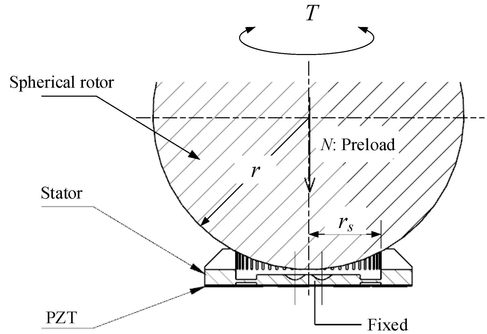
Figure 1, the stator of the motor was pasted with a lead zirconate titanate (PZT) board, which was driven by two alternating voltages with a phase difference. The stator was excited to produce two standing waves, which superimposed into a traveling wave. As a consequence, the points on the stator surface underwent a slightly elliptical motion. Since there was a preload between the stator and rotor, the rotor was driven to rotate through the friction between the stator and rotor.
The driving torque
T is expressed as:
where
r is the radius of rotor,
rs is the radius of contact circle between stator and rotor,
µ is the friction coefficient of the contact layer between the stator and the rotor,
N is the preload between the stator and the rotor. Let
s be the slip rate of the angular velocity between the stator and the rotor, which is expressed as [
18]:
where
ωs is the ideal angular velocity corresponding to the average tangential velocity of the elliptical motion at the contact point between the stator surface and the rotor, and
ωr is the actual angular velocity of spherical rotor. When the preload or the external torque is too high, the slip rate
s should be 1, which means the rotor cannot rotate. When the preload is appropriate and the external torque is 0, the slip rate
s should be close to 0, which corresponds to a no-load angular velocity. Once the preload
N is set, the relationship between the output torque and the angular velocity should be determined via experiment.
Considering the stick-slip phenomenon of the contact between the stator and the rotor, the friction coefficient
µ is a function of the slip rate, so the torque
T is expressed as:
where
cd reflects the influence of the angular velocity difference between the stator and the rotor on the friction coefficient and can only be determined via experiment.
Figure 2 shows the ring-shaped stator designed in this paper, which had a 40 mm outer diameter and an
rs of about 15 mm. The stator consisted of a PZT board and an elastic body made of tin bronze. The PZT board was bonded on the bottom of the elastic body and was comprised of two polarized regions of phase A and phase B with a one-quarter wavelength difference in between them. The top of the stator was evenly distributed with 42 teeth to amplify the amplitude and improve the speed. The working mode of the stator was B
07, and the resonant frequency was tested to be 44 kHz using a frequency sweep of a laser vibrometer (PSV-400 Polytec GmbH., Karlsruhe, Germany). The spherical rotor had a diameter of 60 mm and was made of polyether ether ketone (PEEK450G, Jianbang Plastics, Changzhou, China), which has the advantages of high temperature resistance, abrasion resistance, corrosion resistance, low density, and easy processability.
3. Experimental Setup
In order to understand the behavior of the proposed ultrasonic motor under different external loads and control strategies, a mechanical characteristics testbed was built and is shown in
Figure 3. It mainly consisted of the stator, spherical rotor, dynamic torque transducer, encoder, and a brake. Unlike common mechanical characteristics testbeds, a small handle was fixed on the right side of the dynamic torque transducer for conducting human–machine force interactions. The preload between the stator and rotor was applied by a screw and disc spring, and was detected by an internal pressure sensor. A dynamic torque transducer was used to detect the output torque of the ultrasonic motor, as well as the interaction torque between the operator and the device when the brake was set to be free. The encoder was an incremental type and was used to measure the angular displacement and velocity of the rotor. The brake was designed based on the principle of friction and could simulate an external variable load through an adjusting screw. Two excitation signals were generated and amplified using a driving circuit board based on programmable system-on-chip (PSoC) technology. Using the board, the frequency and phase difference of the two-phase voltage could be easily changed.
A STM32F4-type control board (Yingshi Digital, Guangzhou, China) was used as a slave computer to collect and process the sensor data and control the ultrasonic motor, and the sampling control period was set to be 5 ms. The whole measurement and control system architecture is shown in
Figure 4.
4. Output Behaviors of the TWUM
The output behaviors of the TWUM were determined using the vibration state of the stator. The alternating voltages applied on the PZT board can be expressed as:
where
A is the amplitude,
f is the frequency, and
φ is the phase difference. Therefore, there were three optional parameters to control. As mentioned previously, the output torque control was uncertain, but we could control the speed of the TWUM by adjusting the three parameters.
Table 1 summarizes the speed regulation mechanisms and characteristics of the three control parameters [
19].
Due to the narrow linear range and the difficulty of achieving a drive circuit, the amplitude modulation mode was not considered in this paper. The frequency modulation and phase shift could be easily achieved using PSoC technology. Experience shows that phase difference modulation has a better stability and compliance than frequency modulation for the control of a TWUM and is smoother when frequent reversing is required [
20]. Hence, the phase difference modulation based on a certain frequency was adopted in this study.
Figure 5 shows the relationship between the steady-state speed and frequency in different directions. Because the stator drove the rotor with teeth on its inner ring, the frequency range was only about 1.5 kHz. As shown in
Figure 5, there was a speed gap when the motor was operated in different directions, which was likely due to the different contact conditions in the forward and reverse directions. Since the stator of the TWUM had a low resistance characteristic near the mechanical resonance frequency, and thus had a better efficiency, the working frequency should be near the right side of the resonance frequency. However, if it is very close to the resonance frequency, there will be a risk of damage to the PZT board. Consequently, the working frequency was selected to be 44.5 kHz.
Figure 6 shows the effects of the phase difference modulation on the steady-state rotary speed of the rotor under various external torques. From the figure, some features can be observed. The output rotary speed decreased with a decrease of the phase difference, and there was a control dead zone of about ±20°. Furthermore, as the load increased, the dead zone expanded slightly. When the load increases to 0.1 Nm, the dead zone expands to about ±35°. On the other hand, when the speed was the same, the output torque tended to increase with the increase of the phase difference, although the relationship was not very linear. This meant that it was possible to control the output torque directly using phase difference modulation.
The main properties of the designed TWUM with a spherical rotor are shown in
Table 2.
5. The Problem of Direct Torque Control
In order to test the effects of the force feedback based on direct torque control of the TWUM, the proportional–integral–derivative (PID)-based control scheme whose task it was to make the motor behave as a linear spring with ideal stiffness of 0.5 mNm/° was formulated, as shown in
Figure 7. When the operator operates the handle to rotate output shaft and the brake is set free, the desired torque
τd is calculated through multiplying the actual angular displacement (
θ0 −
θr) using the virtual stiffness
Kd, where
θ0 is the initial angle of the handle and
θr is the actual angle of the handle. The torque error (
eτ =
τd −
τr) is the input into PID force controller to calculate the control variable, where the
τr is the actual interactive torque imposed by the operator. It is noted that the signal collected by the dynamic torque transducer often contained various noises, which could not accurately reflect the output state of the motor and was not suitable for close-loop control system. Therefore, a low-pass filter circuit and a Kalman filter were used to denoise the original signal [
21]. The phase difference was modulated using a limiting discrete PID controller according to:
In this experiment, the operator rotates the handle backwards and forwards. When the handle is in the initial position, the operator should not feel any resistance. When pushing the handle to rotate, the resistance felt by the operator should be proportional to the angular displacement.
The results given in
Figure 8 show that there was a significant difference between the measured and desired torque with large oscillations of the force feedback. In order to quantify the force feedback effect, the actual stiffness shown in
Figure 8 was calculated from the measured data obtained during the experiment.
When the handle position was close to the initial position, the stiffness value changed greatly. The enlarged view of data plot in
Figure 8b shows that the stiffness value had a large jump when the direction changed. According to the statistics of the stiffness data, the mean value was about 0.483 mNm/° which was close to the desired value, but the standard deviation was about 1.955 mNm/°, which is very large and meant that the operator felt very unreal. The reason seems to be the disadvantage of about ±20° of control dead zone. In addition, Equation (3) shows that the parameters affecting the torque were not easy to determine.
6. Position-Based Impedance Control
Impedance control is an effective control method for providing interaction stability between a robot and its environment. It does not directly control the desired position and force, but the interaction between a robot and its environment is equivalent to an impedance relationship. A general impedance is composed of inertia, a spring, and damping, and the expected interaction force is:
where
K,
B, and
M are the expected stiffness, damping, and inertia coefficients, respectively; and Δ
X is the difference between the reference position and the actual position that produces the desired force.
Figure 9 shows the proposed force feedback control scheme, where position-based impedance control was transformed into admittance control. The interaction torque detected by the torque transducer was calculated through the target admittance, and the modified desired position was input into the inner position control loop to achieve the position tracking, such that the TWUM showed the target dynamic characteristics.
Suppose the motor behaves as a linear spring, then the relationship between the actual torque and the reference position deviation is:
Let
eτ be the torque tracking error, and is expressed as:
where
θd denotes the modified desired angular position. This equation means that
eτ will be close to 0 if accurate position tracking can be achieved. In order to understand the performance of the proposed method, the virtual linear spring and virtual wall experiments based on the impedance control method were conducted.
6.1. Virtual Linear Spring Experiment
The virtual spring experiment was conducted again with the proposed impedance control method, and the results are shown in
Figure 10. The measured torque could track the desired torque well, and the difference between them was small. The operator’s feeling could be reflected by the measured stiffness plot. At most times, the stiffness value was around 0.5 mNm/°. Moreover, the stiffness value did not change greatly when the direction was switched. In the initial period, the operator had not moved the handle yet; this meant that when calculating the stiffness value, there was a nonsense situation where the divisor was 0, and therefore the stiffness has no value. According to the statistics of the stiffness data, the mean value was about 0.492 mNm/° and the standard deviation was 0.098 mNm/°, which was much better than the case in the direct torque control experiment.
It is noted that during the period when the operator started to push the handle, the stiffness value deviated from the desired value greatly and was unstable. This was mainly because the random error of the dynamic torque transducer near the initial position was a large proportion of the measured value, while the relative angular displacement was small.
6.2. Virtual Wall Experiment
Furthermore, in order to test the haptic interaction performance of the device in simulating the force feedback during teleoperation, the virtual wall experiment was conducted. The virtual wall model is a simulation of the contact force between remote objects and environmental obstacles, as shown in
Figure 11. When the handle rotates within the range, the expected interaction force of the operator is 0 N. Once the boundary of the virtual wall is reached and crossed, the virtual contact force will be calculated based on the crossed distance and stiffness of the virtual wall model, and input into the force controller as the reference.
In this experiment, the boundary of the virtual wall was set to ±45°. Two cases with virtual stiffnesses of 1 mNm/° and 4 mNm/° were verified, and the results are shown in
Figure 12 and
Figure 13, respectively.
Figure 12a and
Figure 13a show the comparison between the measured and desired torques in the interaction, and
Figure 12b and
Figure 13b show the measured and reference positions of the handle. From
Figure 12, when the position of the handle was within the range of the virtual wall, the interaction torque was almost 0 mNm, and a similar case is seen in
Figure 13. In
Figure 12, when the handle position was outside the virtual wall, the interaction torque could track the desired torque well. The maximum angular displacement was about −140°, which corresponds to a virtual desired torque of about 95 mNm, which was less than the stalling torque of the USM, and the measured torque was very close to the desired value.
Figure 13 shows that the interaction torque could track the desired torque well until the desired torque was over the stalling torque of the USM. If the position of the handle was at or over the angular displacement of ±75°, the feedback torque was maintained around 120 mNm, which was about the stalling torque of the USM.
In addition, there was no obvious torque overshoot when the virtual wall was crossed, which meant that the impedance control method could work well in the haptic interaction system based on an ultrasonic motor.
7. Discussion
A position-based impedance control method was proposed for a TWUM with a spherical rotor that was prepared for haptic interactions. Force feedback control experiments were conducted to verify the effects of the proposed method. Results show that position-based impedance control method had a better performance than direct torque control. Due to the precise motion control characteristics of an ultrasonic motor, when it was used in the haptic interactions, it was better to adopt the position-based impedance control with force detection to achieve the compliance. Furthermore, the accuracy of the force measurement had a great influence on the force feedback effect, especially when the measured value was small. The sampling control period also had some influence on the effect of the force interaction, where if a higher sampling control frequency was adopted, the accuracy of the force interaction was improved. In this study, the driving mode of the TWUM was phase difference regulation based on a fixed frequency, which has limitations due to the control dead zone. In the future, the hybrid control mode will be further explored to improve the motor control effect, thereby further improving the force feedback performance.
Author Contributions
Conceptualization, Y.G. and A.S.; data curation, Y.G.; funding acquisition, Y.G., A.S., and Z.S.; investigation, Y.G.; methodology, Y.G.; project administration, Y.G.; software, Y.G.; validation, Y.G., A.S., and Z.S.; Writing—original draft, Y.G.; Writing—review and editing, A.S. and Z.S.
Funding
This research was funded by the Natural Science Foundation of Jiangsu Province, China (grant number BK20170119), and the National Natural Science Foundation of China (grant number 51775274).
Conflicts of Interest
The authors declare no conflict of interest.
References
- Dehez, B.; Galary, G.; Grenier, D.; Raucent, B. Development of a spherical induction motor with two degrees of freedom. IEEE Trans. Magn. 2006, 42, 2077–2089. [Google Scholar] [CrossRef]
- Fernandes, J.F.P.; Vieira, S.M.; Branco, P.J.C. Multiobjective optimization of a shell-like induction spherical motor for a power-assisted wheelchair. IEEE Trans. Energy Convers. 2017, 33, 660–669. [Google Scholar] [CrossRef]
- Nishizawa, U.; Oohashi, T.; Toyama, S. Evaluation of spherical ultrasonic motor for space in low temperature condition. J. Vibroeng. 2017, 19, 5170–5181. [Google Scholar] [CrossRef]
- Shi, S.J.; Huang, Z.B.; Yang, J.Y.; Liu, Y.X.; Chen, W.S.; Uchino, K. Development of a compact ring type MDOF piezoelectric ultrasonic motor for humanoid eyeball orientation system. Sens. Actuators A Phys. 2018, 272, 1–10. [Google Scholar] [CrossRef]
- Kawano, H.; Ando, H.; Hirahara, T.; Yun, C.; Ueha, S. Application of a multi-DOF ultrasonic servomotor in an auditory tele-existence robot. IEEE Trans. Robot. 2005, 21, 790–800. [Google Scholar] [CrossRef]
- Hoshina, M.; Mashimo, T.; Fukaya, N.; Matsubara, O.; Toyama, S. Spherical ultrasonic motor drive system for camera orientation in pipe inspection. Adv. Robot 2013, 27, 199–209. [Google Scholar] [CrossRef]
- Oohashi, T.; Toyama, S. Development of spherical ultrasonic motor for space. Appl. Mech. Mater. 2014, 555, 26–31. [Google Scholar] [CrossRef]
- Takemura, K.; Maeno, T. Design and control of an ultrasonic motor capable of generating multi-DOF motion. IEEE/ASME Trans. Mechatron. 2001, 6, 499–506. [Google Scholar] [CrossRef]
- Zhang, X.F.; Zhang, G.; Nakamura, K.; Ueha, S. A robot finger joint driven by hybrid multi-DOF piezoelectric ultrasonic motor. Sens. Actuators A Phys. 2011, 169, 206–210. [Google Scholar] [CrossRef]
- Xu, Z.K.; Jin, L.; Hu, M.Q.; Gu, J.P. Research on a novel 3-DOF ultrasonic motor with two cylinder stators. Micromotors 2009, 42, 27–29. [Google Scholar]
- Zhang, J.T.; Jin, J.M.; Zhao, C.S. Novel multi-DOF ring-shaped standing-wave type of ultrasonic motor. J. Vib. Shock 2011, 30, 223–225. [Google Scholar]
- Aovagi, M.; Tomikawa, T.; Takano, T. A novel ultrasonic motor with a built-in clutch mechanism for a force-feed-back actuator. In Proceedings of the IEEE Ultrasonics Symposium, Montreal, QC, Canada, 24–27 August 2004; pp. 2239–2242. [Google Scholar]
- Chapuis, D.; Gassert, R.; Burdet, E.; Bleuler, H. Hybrid ultrasonic motor and electrorheological clutch system for mr-compatible haptic rendering. In Proceedings of the 2006 IEEE/RSJ International Conference on Intelligent Robots and Systems, Beijing, China, 9–15 October 2006; pp. 1553–1557. [Google Scholar]
- Giraud, F.; Semail, B.; Audren, J.T. Analysis and phase control of a piezoelectric traveling-wave ultrasonic motor for haptic stick application. IEEE Trans. Ind. Appl. 2004, 40, 1541–1549. [Google Scholar] [CrossRef]
- Maas, J.; Schulte, T.; Frohleke, N. Model-based control for ultrasonic motors. IEEE/ASME Trans. Mechatron. 2000, 5, 165–180. [Google Scholar] [CrossRef]
- Seigler, T.M.; Venkatesan, N.; Inman, D. An approach to force-feedback control with traveling wave ultrasonic motor. J. Intell. Mater. Syst. Struct. 2009, 20, 1393–1400. [Google Scholar] [CrossRef]
- Giraud, F.; Amberg, M.; Lemaire-Semail, B. Control of a haptic interface actuated by ultrasonic motors. In Proceedings of the 14th International Power Electronics and Motion Control Conference (EPE-PEMC 2010), Ohrid, Republic of Macedonia, 6–8 September 2010; pp. T4-86–T4-89. [Google Scholar]
- Mashimo, T.; Toyama, S.; Ishida, H. Design and implementation of spherical ultrasonic motor. IEEE Trans. Ultrason. Ferroelectr. Freq. Control 2009, 56, 2514–2521. [Google Scholar] [CrossRef] [PubMed]
- Zhao, C.S. Ultrasonic Motors: Technologies and Applications; Springer: Berlin/Heidelberg, Germany, 2011. [Google Scholar]
- Nishizawa, U.; Toyama, S. Phase difference control system for TR motor. Appl. Mech. Mater. 2016, 841, 173–178. [Google Scholar] [CrossRef]
- Pai, A.D.; Umanand, L.; Rao, N.J. Direct torque control of induction motor with extended Kalman filter. In Proceedings of the 3th International Power Electronics and Motion Control Conference (IPEMC 2000), Beijing, China, 15–18 August 2000; pp. 132–137. [Google Scholar]
© 2019 by the authors. Licensee MDPI, Basel, Switzerland. This article is an open access article distributed under the terms and conditions of the Creative Commons Attribution (CC BY) license (http://creativecommons.org/licenses/by/4.0/).


