Article

3-D SRIM Simulation of Focused Ion Beam Sputtering with an Application-Oriented Incident Beam Model

1
Key Laboratory of Micro-nano Measurement-Manipulation and Physics (Ministry of Education), School of Physics, Beihang University, Beijing 100191, China
2
Institute of Electrical Engineering, Chinese Academy of Sciences, Beijing 100190, China
3
University of Chinese Academy of Sciences, Beijing 100190, China
*
Author to whom correspondence should be addressed.
Appl. Sci. 2019, 9(23), 5133; https://doi.org/10.3390/app9235133
Submission received: 29 October 2019 / Revised: 19 November 2019 / Accepted: 21 November 2019 / Published: 27 November 2019
(This article belongs to the Section Nanotechnology and Applied Nanosciences)

Abstract

:
Ion beam sputter etching has been widely used in material surface modification and transmission electron microscope (TEM) sample preparation. Due to the complexity of the ion beam etching process, the quantitative simulation of ion beam sputtering is necessary to guarantee precision in surface treatment and sculpting under different energies and beam currents. In this paper, an application-oriented incident ion beam model was first built with aberrations and Coulomb repulsion forces being considered from the Ga ion source to the sample. The sputtering process of this model on the sample was then analyzed and simulated with an improved stopping and range of ions in metter (SRIM) program. The sputtering performance of this model, the point-like incident beam and the typical Gaussian incident beam was given in the end. Results show that the penetration depth of Ga ions having 30 keV energy in silicon is 28 nm and the radial range is 29.6 nm with 50 pA beam current. The application-oriented model has been verified by our focused ion beam-scanning electron microscopy (FIB-SEM) milling experiment and it will be a potential thermal source in simulating the process of FIB bombarding organic samples.

Graphical Abstract

1. Introduction

The Focused Ion Beam (FIB) instrument has been developing since developments in the liquid metal ion source (LMIS) during the 1970s [1,2,3,4]. It has become one of the most important micro/nano manufacturing tools for its direct patterning, high resolution and its multi-role in the semiconductor field [5,6]. It can be used for transmission electron microscopy (TEM) sample preparation [7,8,9,10], direct and mask-less 3-D patterning [11,12,13], semiconductor integrated circuit failure analysis [14,15], and solid oxide cell (SOC) fabrication [16]. Theories on ion-solid interaction and the relative simulation methods have developed rapidly along with the expansion of FIB application.
Among all the methods to simulate ion-solid interaction, Monte-Carlo is popular and succeeds in forming software such as SRIM and TRIM [17], TRIDYN [18], SDTrimSP [19] and so forth. SRIM is based on TRIM (transaction of ions in matter) using short-range ZBL potential. TRIDYN is an improved version of TRIM code allowing dynamic simualtions with Krypton-Carbon interaction potential. SDTrimSP (SD for static–dynamic; SP for sequential and parallel processing) is based on TRIDYN code and used for sputtering process of low energy. Hofsäss et al. studied the angle-dependent sputter yields with SDTrimSP, TRIDYN and SRIM [20]. Schmied et al. combined SRIM and the thermal spike model to research the spatial and temperature evolution through the Gaussian profile beam of soft matter [21]. Toussaint et al. analyzed the sputtering of 3-D rough samples with arbitrary 3-D surface morphologies [22]. Ali et al. developed the mathematical model for sputtering sidewall with the beam radius, the substrate material properties and the supposed Gaussian beam current density [23], which is verified by the experiment of a single crystal (100) silicon [24]. In the above studies, sputtering objectives such as sputtering depth and radial range are mainly affected by parameters of the incident ion beam and samples. Normally, parameters of the incident ion beam include ion dose, ion energy, incident angle and Gaussian beam current density. However, these conclusions are not suitable for the FIB system as the Coulomb repulsion forces among ions make the incident beam different from the ideal Gaussian distribution and this change will influence the sputtering performance accordingly [25,26]. Furthermore, FIB distributions are different under different beam energies and beam currents [27,28]. In order to guarantee the precision in FIB fabrication under different beam energies and beam currents, a new application-oriented model including aberrations and Coulomb repulsion forces was brought forward in simulating ion-solid interaction.
In this paper, the sputtering process of the high-energy ion beam on the sample was researched firstly under different beam energies, ion doses and incident angles. Ion-solid interaction was then simulated through the improved SRIM program with an application-oriented ion beam model, whose beam current distributions include aberrations and Coulomb repulsion forces among ions. In the end, the sputtering performance of this model and its comparison to the typical Gaussian incident beam were given in detail.

2. Theory on Ion-Solid Interaction

A series of physics-chemistry actions will occur when high-energy ion beam bombarding the sample as shown in Figure 1. Sputtering depth and radial range are discussed as they affect the precision of FIB sputtering greatly. If non-redeposition of the sputtered atoms, same material removal rate and Gaussian distribution incident beam are assumed during the bombardment [29], the sputtering depth can be expressed in Equation (1).
Δ Z i j = Σ k = 1 n 1 Σ l = 1 n 2 ϕ ( x k , y l ) η f x k , y l ( x i , y j ) S ( θ x i , y j ) t x k y l Δ x k Δ y l ,
where Δ Z i j is the sputtering depth at point ( x i , y j ) , ϕ ( x k , y l ) is the ion flux with the unit of cm 2 s 1 , η is the atomic density of the target with the unit of atom·cm 3 , f x k , y l ( x i , y j ) is the ion beam current density function for the Gaussian distribution, S ( θ x i , y j ) is the angle-dependent sputtering yield, θ x i , y j is the incident angle, t x k y l represents the dwell time, ( x i , y j ) is the midpoint of each pixel ( x k , y l ) , and i = 1 n 1 , j = 1 n 2 , n 1 , n 2 are the number of square pixels along x and y axes. Under the Gaussian distribution, the ion beam current density function will satisfy the equation as follows [30]:
f x k , y l ( x i , y j ) = I 2 π σ 2 exp ( x k x i ) 2 + ( y l y j ) 2 2 σ 2 ,
where I is the total ion beam current, i, j, n 1 and n 2 have the same meanings as above, x k and y l are independent of each other and the standard deviation σ represents dispersions of x k and y l upon x i and y j .
According to Equation (1), the sputtering depth depends on the dwell time, the incident angle, the beam current distribution of the incident beam, and the characteristics of the sample. As for the radial range, it depends on the sputtering depth, original ion position, speed and so forth. It is necessary to determine the beam current distribution of the incident beam before simulating ion-solid interaction.

3. Application-Oriented Model of Incident Beam

Coulomb force interaction among ions cannot be neglected, especially in low energy, which deflects the beam current distribution at the sample from the ideal Gaussian distribution. Coulomb force interaction will change under different beam currents and beam current densities. In order to find the ion-solid interaction under different beam energies and beam currents, an application-oriented model was brought forward.
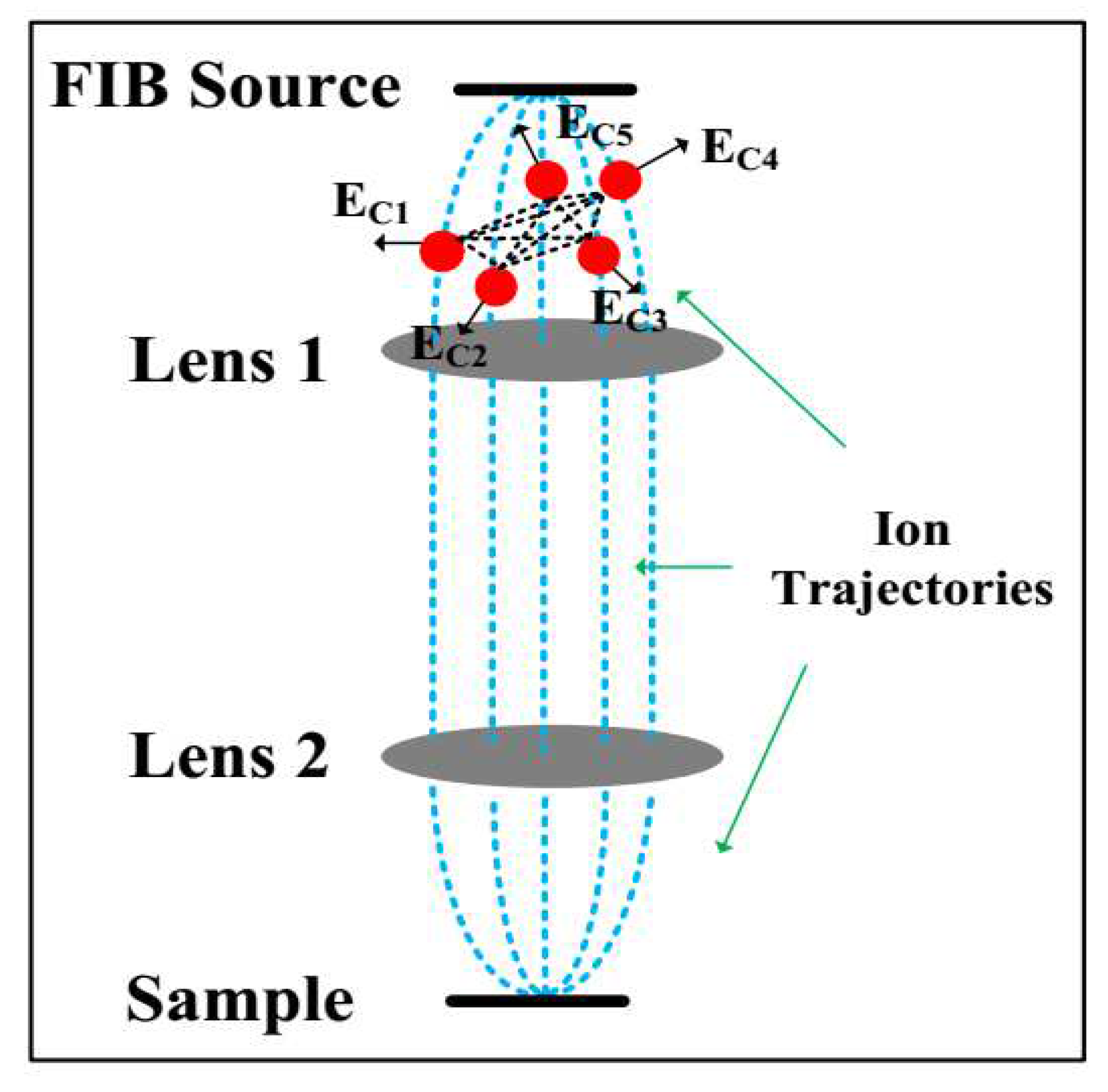
In this new model, the ion beam current density distribution was obtained by tracing the incident ions in three dimensions [31] from the source to the surface of the sample with lens aberrations and Coulomb force interaction being considered as shown in Figure 2. Three-dimensional ion trajectories were obtained by solving Newton-Lorentz equations of ions with original random conditions at FIB source. For a typical FIB source, its beam current density satisfies Gaussian distribution as shown in Figure 3. Newton-Lorentz equations of ions can be expressed as:
F = m a i = q E i = q ( E E i + E C i ) , f o r i = 1 , , N
E C i = q 4 π ε 0 i = 1 i j N r i r j r i r j 3 ,
where m is the mass and q is the charge of Ga + , a i is the acceleration, E i is the field strength, E E i and E C i are the electrostatic field and coulomb field at the i-th ion respectively, r i and r j are the positions of i-th and j-th ions and N represents the number of ions in a bunch within which Coulomb forces among ions are considered. N is dependent on the beam energy, beam current and beam current density [31]. Normally, many bunches of ions were calculated to get a good statistical law and the total number of ions is about 10,000.
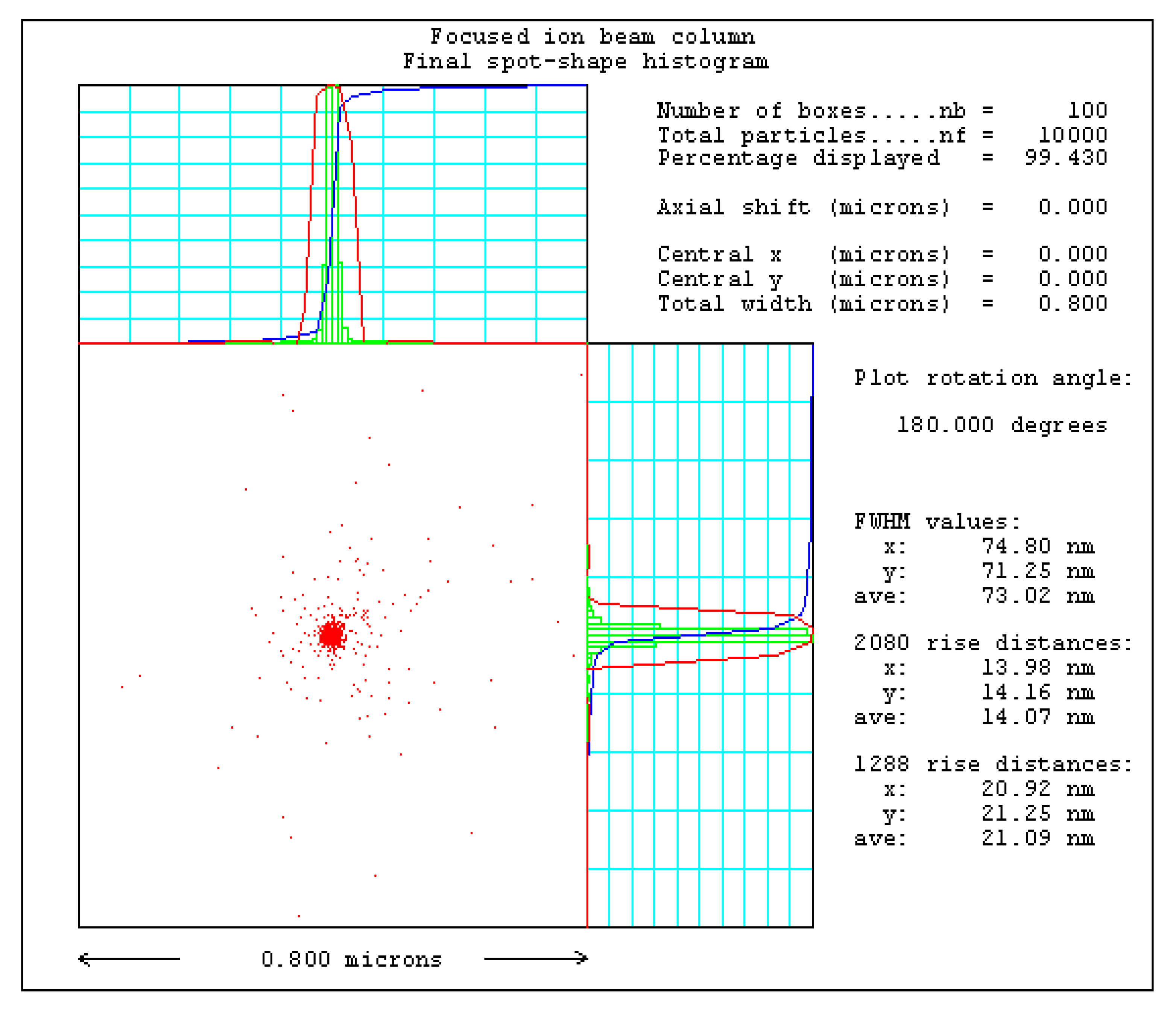
For a 30 keV FIB, the application-oriented model of 50 pA beam current is shown in Figure 4 and its variables such as the lenses and the source originated from the FIB-SEM system in our lab. There are three key parameters to describe the distribution, which are called full width at half maximum (FWHM) values, 20–80% rise distances and 12–88% rise distances. In a Gaussian distribution, 12–88% rise distances can be comparable to FWHM values. Normally, 12–88% rise distances can be used to represent the resolution in charged particle optics. From Figure 4, we can see that the beam current density at the sample is different from a Gaussian distribution. In order to reflect the real incident beam, the application-oriented model was chosen to simulate ion-solid interaction.

4. Results

4.1. Simulation Results

The SRIM program was improved for the application-oriented model by editing the script file with the spatial positions and landing angles of all ions at the surface of Si substrate. In order to research the sputtering performance systematically, the point-like incident beam, the Gaussian distribution beam with the same beam energy and beam spot and the application-oriented model were simulated with the same energy and dose. Three-dimensional scattering distributions in the substrate and the relative lateral range cross-sections (XOY) for 30 keV Ga + are shown in Figure 5. The point-like mono-energetic Ga + beam is clustered at the top of the substrate as shown in Figure 5a. While in Figure 5c,e, the beam distribution becomes tapered with the depth, which is consistent with the actual condition. The actual nanowires are “V” shape since the sputtered atoms are redeposited on the sidewalls in etching. Judging from Figure 5b,d,f, these three incident beams have the same penetration depth of 280 Å for Ga + implantation concentration, which is consistent with the measured parameters in the experiment [32,33].
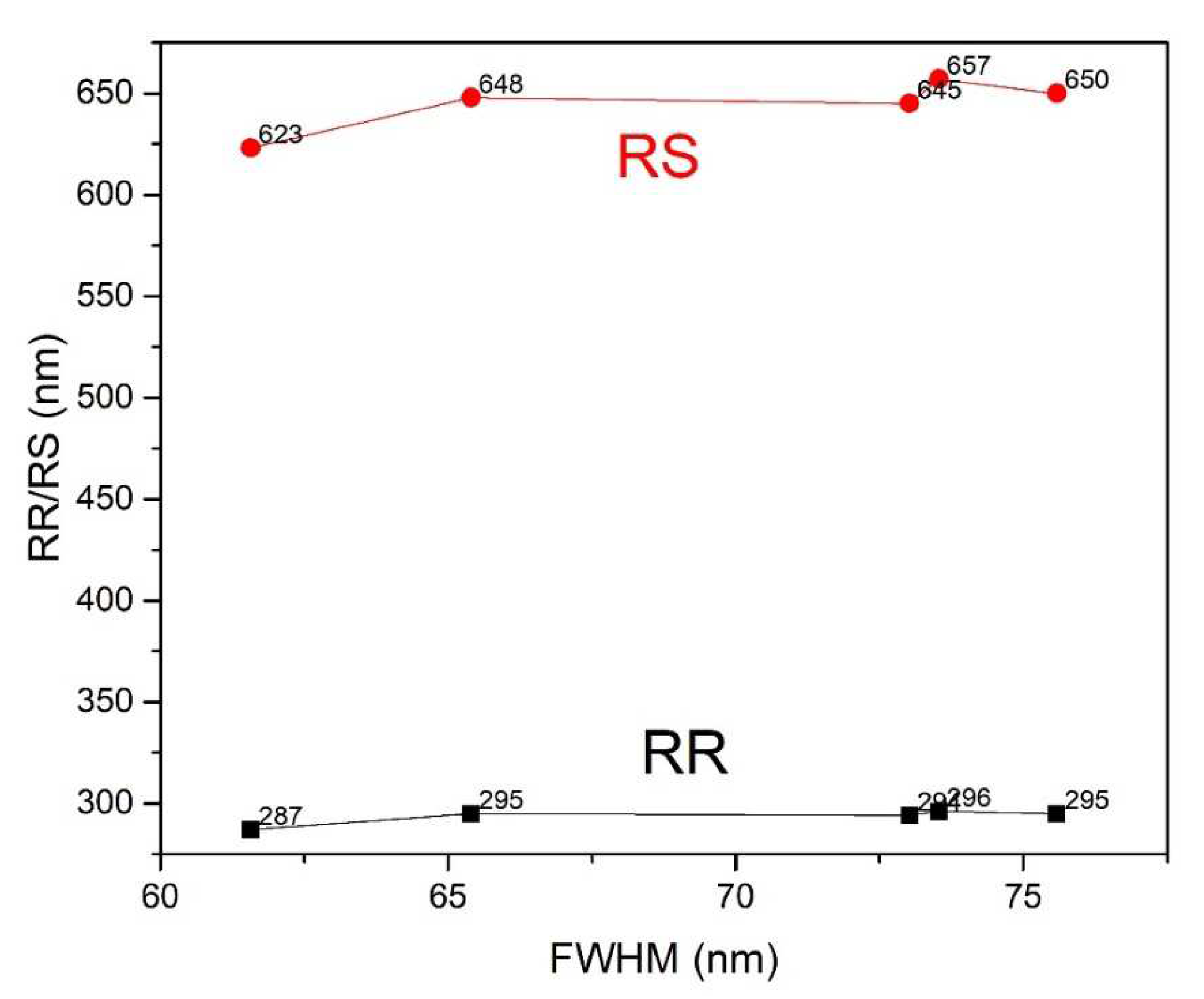
Quantitative behaviors for three incident beams in Figure 5 were listed in Table 1. The longitudinal range is keeping 280 Å as mentioned above and the longitudinal straggle of the point-like incident beam is just 1 Å smaller than the other models. But the lateral projection, the lateral projection straggle, the radial range and the radial straggle differ a lot for different models. The application-oriented model has the largest radial range and the main cause may be that the model itself has the largest FWHM value. In order to verify the above conclusion, the radial range (RR) and radial straggle (RS) under different FWHM values with the new model were simulated as shown in Figure 6. Judging from Figure 6, RR and RS increase with FWHM value and become stable at about 75.5 nm where the 20–80% rise distances and the 12–88% rise distances are much smaller than FWHM value. Since the radial range depends on the original spatial position of the incident beam, the model with aberrations and the Coulomb force interaction is more applicable. Furthermore, ion-solid interaction under different beam energy and beam currents can be obtained by using the application-oriented model.

4.2. Experimental Results

Figure 7 shows the periodic nanograting etched on Si substrate with our 30 keV FIB-SEM system. For some mechanical limit, its shortest working distance of FIB is 12 mm. In Figure 7, the line width is 35 nm when the beam current is 50 pA and the dwell time is 30 s, which agrees with the simulation result of the application-oriented model.

5. Conclusions

In this paper, an application-oriented incident model was realized by solving the Newton-Lorentz ion motion equations with aberrations and Coulomb repulsion forces being considered. The generated application-oriented ion beam current density distribution was used to simulate ion-solid interaction by modifying the SRIM script file. Results show that the penetration depth of 30 keV Ga + in silicon is 28 nm and the radial range is 29.6 nm under 50 pA with this new model. Compared with the point-like incident beam and the Gaussian distribution beam, the application-oriented model has a better agreement with the experimental result. Also, ion-solid interaction under different beam energy and beam currents can be realized with this new model.
When high energy ion bombards samples, it will generate lots of heat and make organic samples deformed. The transformation of the kinetic energy to the thermal energy needs to be studied for organic samples. With 3-D ion beam current density distribution, the application-oriented model will be a potential thermal source in simulating the process of FIB bombarding organic samples in the future.
References

Author Contributions

Conceptualization, W.L.; methodology, L.Z. and W.L.; formal analysis, W.L., L.Z. and W.A.K.; writing-original draft preparation, L.Z.; writing-review and editing, W.L., Y.C. and Y.M.

Funding

This research was supported by the National Natural Science Foundation of China (Grant No. 11205012) and scientific research and instrument development project of Chinese Academy of Sciences (Grant No. YZ201410).

Conflicts of Interest

The authors declare no conflict of interest.

References

  1. Krohn, V.E.; Ringo, G.R. Ion source of high brightness using liquid metal. Appl. Phys. Lett. 1975, 27, 479. [Google Scholar] [CrossRef]
  2. Gierak, J. Focused ion beam technology and ultimate applications. Semicond. Sci. Technol. 2009, 24, 043001. [Google Scholar] [CrossRef]
  3. Kim, C.S.; Ahn, S.H.; Jang, D.Y. Review: Developments in micro/nanoscale fabrication by focused ion beams. Vacuum 2012, 86, 1014–1035. [Google Scholar] [CrossRef]
  4. Bassim, N.; Scott, K.; Giannuzzi, L.A. Recent advances in focused ion beam technology and applications. MRS Bull. 2014, 39, 317–325. [Google Scholar] [CrossRef]
  5. Orloff, J. High-resolution focused ion beams. Rev. Sci. Instrum. 1993, 64, 1105. [Google Scholar] [CrossRef]
  6. Volkert, C.A.; Minor, A.M. Focused ion beam microscopy and micromachining. MRS Bull. 2007, 32, 389–395. [Google Scholar] [CrossRef]
  7. Nalla, R.K.; Porter, A.E.; Daraio, C.; Minor, A.M.; Radmilovic, V.; Stach, E.A.; Tomsia, A.P.; Ritchie, R.O. Ultrastructural examination of dentin using focused ion-beam cross-sectioning and transmission electron microscopy. Micron 2005, 36, 672–680. [Google Scholar] [CrossRef]
  8. Mayer, J.; Giannuzzi, L.A.; Kamino, T.; Michael, J. TEM sample preparation and FIB-induced damage. MRS Bull. 2007, 32, 400–407. [Google Scholar] [CrossRef]
  9. Ciobanu, C.L.; Cook, N.J.; Utsunomiya, S.; Pring, A.; Green, L. Focussed ion beam–transmission electron microscopy applications in ore mineralogy: Bridging micro- and nanoscale observations. Ore. Geol. Rev. 2011, 42, 6–31. [Google Scholar] [CrossRef]
  10. Clancy, M.; Pomeroy, M.J.; Belochapkine, S. Improved FIB milling process for TEM preparation of NiAlPt bulk alloy samples containing residual stress. Micron 2012, 43, 627–630. [Google Scholar] [CrossRef]
  11. Tseng, A.A. Recent developments in micromilling using focused ion beam technology. J. Micromech. Microeng. 2004, 14, R15–R34. [Google Scholar] [CrossRef]
  12. Ahn, S.H.; Yoon, H.S.; Jang, K.H.; Kim, E.S.; Lee, H.T.; Lee, G.Y.; Kim, C.S.; Cha, S.W. Nanoscale 3D printing process using aerodynamically focused nanoparticle (AFN) printing, micro-machining, and focused ion beam (FIB). CIRP Ann. 2015, 64, 523–526. [Google Scholar] [CrossRef]
  13. Prosa, T.J.; Larson, D.J. Modern Focused-Ion-Beam-Based Site-Specific Specimen Preparation for Atom Probe Tomography. Microsc. Microanal. 2017, 23, 194–209. [Google Scholar] [CrossRef] [PubMed]
  14. Gerlach, R.; Utlaut, M. Focused ion beam methods of nanofabrication: Room at the bottom. Charg. Part. Detect. Diagn. Imaging 2001, 4510, 96–106. [Google Scholar]
  15. Lepinay, K.; Lorut, F. Three-Dimensional Semiconductor Device Investigation Using Focused Ion Beam and Scanning Electron Microscopy Imaging (FIB/SEM Tomography). Microsc. Microanal. 2013, 19, 85–92. [Google Scholar] [CrossRef]
  16. Holzer, L.; Wiedenmann, D.; Munch, B.; Keller, L.; Prestat, M.; Gasser, P.; Robertson, I.; Grobety, B. The influence of constrictivity on the effective transport properties of porous layers in electrolysis and fuel cells. J. Mater. Sci. 2013, 48, 2934–2952. [Google Scholar] [CrossRef]
  17. Ziegler, J.; Biersack, J.P.; Ziegler, M.D. Ion Straggle and TRIM: Output Files. In The Stopping and Range of Ions in Matter; Springer: Boston, MA, USA, 2008. [Google Scholar]
  18. Drobny, J.; Curreli, D. F-TRIDYN simulations of tungsten self-sputtering and applications to coupling plasma and material codes. Comp. Mater. Sci. 2018, 149, 301–306. [Google Scholar] [CrossRef]
  19. Mutke, A.; Schneider, R.; Bandelow, G. SDTrimSP-2D: Simulation of particles Bombarding on a Two Dimensional Target (Version 2.0)(IPP 12/11); Max-Planck-Institut für Plasmaphysik: Garching, Germany, 2013. [Google Scholar]
  20. Hofsass, H.; Zhang, K.; Mutzke, A. Simulation of ion beam sputtering with SDTrimSP, TRIDYN and SRIM. Appl. Surf. Sci. 2014, 310, 134–141. [Google Scholar] [CrossRef]
  21. Schmied, R.; Froch, J.E.; Orthacker, A.; Hobisch, J.; Trimmel, G.; Plank, H. A combined approach to predict spatial temperature evolution and its consequences during FIB processing of soft matter. Phys. Chem. Chem. Phys. 2014, 310, 6153–6158. [Google Scholar] [CrossRef]
  22. Von Toussaint, U.; Mutzke, A.; Manhard, A. Sputtering of rough surfaces: A 3D simulation study. Phys. Scr. 2017, 170, 014056. [Google Scholar] [CrossRef]
  23. Ali, M.Y.; Hung, N.P.; Ngoi, B.K.A.; Yuan, S. Sidewall surface roughness of sputtered silicon I: Surface modelling. Surf. Eng. 2003, 19, 97–103. [Google Scholar] [CrossRef]
  24. Ali, M.Y.; Hung, N.P.; Ngoi, B.K.A.; Yuan, S. Sidewall surface roughness of sputtered silicon II: Model verification. Surf. Eng. 2003, 19, 104–108. [Google Scholar] [CrossRef]
  25. Orloff, J. Resolution. In Handbook of Charged Particle Optics; CRC Press: Boca Raton, FL, USA, 1997; pp. 392–434. [Google Scholar]
  26. Lugstein, A.; Basnar, B.; Hobler, G.; Bertagnolli, E. Current density profile extraction of focused ion beams based on atomic force microscopy contour profiling of nanodots. J. Appl. Phys. 2002, 92, 4037–4042. [Google Scholar] [CrossRef]
  27. Marianowski, K.; Ohnweiler, T.; Plies, E. Coulomb interactions in a low-voltage focussed ion beam system. Nucl. Instr. Methods Phys. Res. Sect. 2011, 645, 116–119. [Google Scholar] [CrossRef]
  28. Shorubalko, I.; Choi, K.; Stiefel, M.; Park, H.G. Ion beam profiling from the interaction with a freestanding 2D layer. Beilstein J. Nanotechnol. 2017, 8, 682–687. [Google Scholar] [CrossRef] [PubMed]
  29. Nassar, R. Mathematical modeling of focused ion beam microfabrication. J. Vac. Sci. Technol. B 1998, 16, 109. [Google Scholar] [CrossRef]
  30. Ali, M.Y.; Hung, W.; Fu, Y.Q. A Review of Focused Ion Beam Sputtering. Int. J. Precis. Eng. Manuf. 2010, 11, 157–170. [Google Scholar] [CrossRef]
  31. Munro, E.; Rouse, J.; Liu, H.; Wang, L.; Zhu, X. Simulation software for designing electron and ion beam equipment. Microelectron. Eng. 2006, 83, 994–1002. [Google Scholar] [CrossRef]
  32. Munro, E.; Rouse, J.; Liu, H.; Wang, L.; Zhu, X.; Wang, J.B.; Wang, Y.L. A novel procedure for measuring the absolute current density profile of a focused gallium-ion beam. Appl. Phys. Lett. 1996, 69, 2764–2766. [Google Scholar]
  33. Hung, N.P.; Fu, Y.Q.; Ali, M.Y. Focused ion beam machining of silicon. J. Mater. Process. Technol. 2002, 127, 256–260. [Google Scholar] [CrossRef]
Figure 1. Ion-solid interaction schematic diagram.
Applsci 09 05133 g001
Figure 2. Ion motion trajectories and Coulomb forces among ions.
Applsci 09 05133 g002
Figure 3. Gaussian distribution with the virtual source diameter being 50 nm.
Applsci 09 05133 g003
Figure 4. Application-oriented incident model at the surface of the sample with 50 pA beam current and 12 mm working distance.
Applsci 09 05133 g004
Figure 5. Three-dimensional final ion scattering distributions and relative horizontal (XOY) views with 10,000 30 keV ions. (a,b) are 3-D ion scattering distribution and ion distribution versus penetration depth of the point-like incident beam; (c,d) are 3-D ion scattering distribution and ion distribution versus penetration depth of the Gaussian profile incident beam; (e,f) are 3-D ion scattering distribution and ion distribution versus penetration depth of the new model.
Applsci 09 05133 g005
Figure 6. RR/RS varies with FWHM value while the beam spot (20–80% rise distances) is 14 nm and the beam spot (12–88% rise distances) is 21 nm.
Applsci 09 05133 g006
Figure 7. Milling experiment of 30 keV FIB on the silicon substrate.
Applsci 09 05133 g007
Table 1. Simulation results of three incident models.
Point-Like IncidentGaussian Distribution BeamApplication-Oriented Model
Longitudinal Range280 Å280 Å280 Å
Longitudinal Straggle103 Å104 Å104 Å
Lateral Proj. Range65 Å106 Å188 Å
Lateral Proj. Straggle83 Å133 Å503 Å
Radial Range102 Å166 Å296 Å
Radial Straggle59 Å88 Å657 Å