Article

Decarbonising the Shipping Sector: A Critical Analysis on the Application of Waste Heat for Refrigeration in Fishing Vessels

1
National Council or Research Italy, Institute for Advanced Energy Technologies (CNR ITAE), Salita S. Lucia sopra Contesse 5, 98126 Messina, Italy
2
Department of Mechanical Engineering, University of Malta, MSD 2080 Msida, Malta
*
Author to whom correspondence should be addressed.
Appl. Sci. 2019, 9(23), 5143; https://doi.org/10.3390/app9235143
Submission received: 23 October 2019 / Revised: 8 November 2019 / Accepted: 18 November 2019 / Published: 27 November 2019
(This article belongs to the Section Energy Science and Technology)

Abstract

:

Featured Application

Improvement of ship sector with the reduction of emissions due to the refrigeration system.

Abstract

The integration of sorption systems on-board fishing vessels has been explored in the last decade, but the limitations in power density and temperature levels achievable have hindered their application. In the present paper, the integration of hybrid sorption–compression systems was evaluated. Different shipping vessels and routes in seas and oceans were considered in the analysis, with engine powers from 190 kW to 500 kW. The feasibility of series and cascade configurations was studied and the possible benefits, in terms of fuel and CO2 savings, were evaluated. The analysis, which also considered the payload due to the extra fuel needed to transport the equipment for refrigeration, showed that up to 75% savings can be obtained, with CO2 emissions avoided up to 20 t/y.

1. Introduction

The shipping sector is responsible for 2.5% of worldwide Greenhouse Gas emissions (GHG) annually [1], and therefore increasing attention and effort is being devoted to the decarbonisation of the shipping sector, through several energy audit initiatives [2], as well as international policies devoted to the improvement of the energy efficiency of ships [3] and research for technical solutions to increase the sustainability of the sector [4]. Within this wide and complex sector, the fishing field, with a total fleet of around 4.4 million vessels globally, has a strong impact on the overall effect of the shipping sector on climate change.
Different alternatives have been suggested for the improvement of the energy valorisation on ships, starting from the analysis of the several sources of inefficiencies [5] and load distribution [6]. Among the solutions proposed, different power cycles, including Organic Rankine Cycles (ORC), Rankine, Kalina, and their combinations, for the production of steam and electricity were evaluated [7], even though the complexity of the system was found to represent a serious drawback for practical installation, especially considering the limited benefits, especially for long-distance shipping.
On the contrary, the use of waste heat from the engine, which represents up to 50% of the overall energy output of the engine [8] for heating and cooling purposes, is a valid solution for the valorisation of an amount of energy that is generally considered as a contribution to the exergy destroyed. Indeed, the impact of refrigeration on the fuel consumption and, consequently, CO2 emissions is relevant: the small pelagics fish, which are the most efficient in terms of fuel intensity, require up to 1000 L of fuel per ton of fish refrigerated and transported, whereas crustacean require up to 6000 L of fuel per ton [9]. Hence, it is clear that there is a significant space for energy efficiency improvement in the sector.
During the last decade, several refrigerators and chillers that can be powered by waste heat were studied. A detailed review is presented in [10]. The systems proposed up to now are mainly ice makers, based on a discontinuous cycle for the production of ice flakes [11], chillers for air conditioning application on-board [12], and refrigerators for continuous cooling production at different temperature levels [13,14,15]. The application in an aggressive environment, such as the marine one, was specifically addressed in the design of various systems, considering corrosion issues and the effect of the movement of the ship [16,17].
From such a literature review, it is clear that the vast majority of studies available are concentrated on the thermodynamic and dynamic efficiency of the system [17], or the development of prototypes for application on-board [18,19,20] and their testing [15,21]. Only a few studies have actually considered how the whole energy system could be included on-board and the possible implications of the installation of such a system. For instance, in [14,22], a complete system for providing heating, cooling, and refrigeration demand on a container ship was modelled in the dynamic systems modelling software TRNSYS, thus considering, on the one hand, the dynamic behaviour under realistic conditions, and on the other hand, the actual connections of all the components of the system. In [20], the effect of the sorption system was evaluated, in terms of weight and therefore extra fuel consumption, proving that the benefits arising from the use of such a system are strictly dependent on the routes followed and the duration of the cruise. Nonetheless, the integration of these innovative energy systems within the ship architecture and its already complex power generation system has not been properly addressed up to now. In [20,23,24], only the waste heat recovery system was included in the energy and environmental analysis of refrigeration systems for fishing vessels. The results, however, demonstrated the need for a careful evaluation of the sorption systems in relation to the operational features of the ship, i.e., days at sea, dimension of the cold room, and so on.
What the previous literature fails to report is the possibility of combining the sorption system with other systems on-board for providing refrigeration and air conditioning with the highest efficiency possible and at different temperature levels. Instead, in the present work, different solutions are proposed and analysed, trying to highlight how the integration of the sorption units for synergic operation with other thermal systems can boost the efficiency and increase the reliability of the energy system. In such a context, the present work aims to give an innovative overview on the feasibility of waste-heat powered systems in fishing vessels, which include not only sorption refrigerators but hybrid solutions that couple sorption and compression systems, analysed for the first time for application on-board. This paper is structured as follows: in Section 2, the methodology is presented; the different cases selected for the application are described in Section 3—particular focus was put on choosing different types of fishing vessels and different typical routes; in Section 4, the sorption systems introduced in the analysis are described; Section 5 presents the schematics for the integration of such systems on-board; Section 6 presents the results of the energy analysis, whereas Section 7 summarises the environmental analysis carried out. Finally, a discussion on the future trends and possibilities for the application of innovative energy systems is reported.

2. Methodology

The methodology followed is shown in Figure 1. The aim of the evaluation carried out was an energy and environmental analysis regarding the application of sorption refrigeration technologies on-board fishing vessels. To this end, a preliminary screening of data available allowed the identification of the boundary operating conditions, based on information from producers and literature data. Great effort was put in the identification of possible integration strategies for sorption chillers. The most promising solutions, in terms of technical feasibility, were further analysed in terms of possible benefits, i.e., by calculating the fuel saved. The effect of the extra weight due to the installation of the sorption system was evaluated as well, in order to take into account also the penalisation due to the presence of bulky components. Finally, the environmental benefits, in terms of emissions saved, were calculated.

3. Identification of Boundary Conditions

3.1. Fishing Vessels

The analysis considered fishing vessels that are representative of the fishing fleet in different countries and climates. Both the case of oceanic navigation, i.e., long distance shipping with several days at sea, and the Mediterranean case, with shorter travel distance and time at sea, were evaluated. Based on the analysis reported in [25] for fishing vessels that included a refrigeration system on board, three cases were selected, mainly differing in the dimensions and prime movers. In addition, according to what was reported in [20], a fourth case was considered, typical of the Mediterranean fleet, a vessel with 10 m3 frozen fish storage, with 10 days of operation. The amount of fish that each vessel could hold was calculated using the cubic number (CUNO) method [26]: the fish hold is equal to CUNO × 0.14, where the CUNO is:
C U N O = L o a × B × D m ,
where Loa is the length overall (m), B is the beam width amidships at deck level (m), and Dm is the distance from deck to keel amidships (m).
The cases investigated are summarised in Table 1. It is clear that the wide variety of the different fishing vessels guarantees the representativeness of the analysis carried out. Nonetheless, the peculiarities of the fishing vessels in different world areas were considered. For instance, as reported in [27], the Italian fleet, which can be considered representative of the overall Mediterranean fleet, is mainly characterised by vessels with a displacement lower than 400 m3 and therefore, the case D is the most representative one, followed by case A. On the contrary, the fishing fleet in the North Sea, comprising several countries (Norway, Belgium, The Netherlands, UK, Denmark) is extremely variable and includes both fishing vessels below 16 m (cases A and D) and bigger fishing trawlers that stay at sea between 20 and 25 days, since the wide availability of different fish species allows for different landings [28]. Regarding the fisheries specifications in the ocean, it is possible to assume that close to the coasts, smaller vessels are used, whereas in deep sea big fishing trawlers with refrigeration facilities can be found, as confirmed in [29], where it was shown that there is not a prevalence of the so-called artisanal fishing boats over the industrial trawlers. The variability considered in the analysis is therefore wider than that usually considered in the scientific literature on the topic [20] and it is meant to give a complete overview regarding the technical and environmental benefits connected to the application of sorption systems, also under conditions not investigated up to now.

3.2. Seawater Conditions

The second parameter needed for the analysis was the temperature of the seawater at the surface and at a short depth (i.e., less than 5 m). Indeed, the refrigeration systems installed on-board exploit such a medium for waste heat rejection and therefore it is a crucial parameter in the definition of the performance of the refrigeration system, for the traditional one and the sorption one.
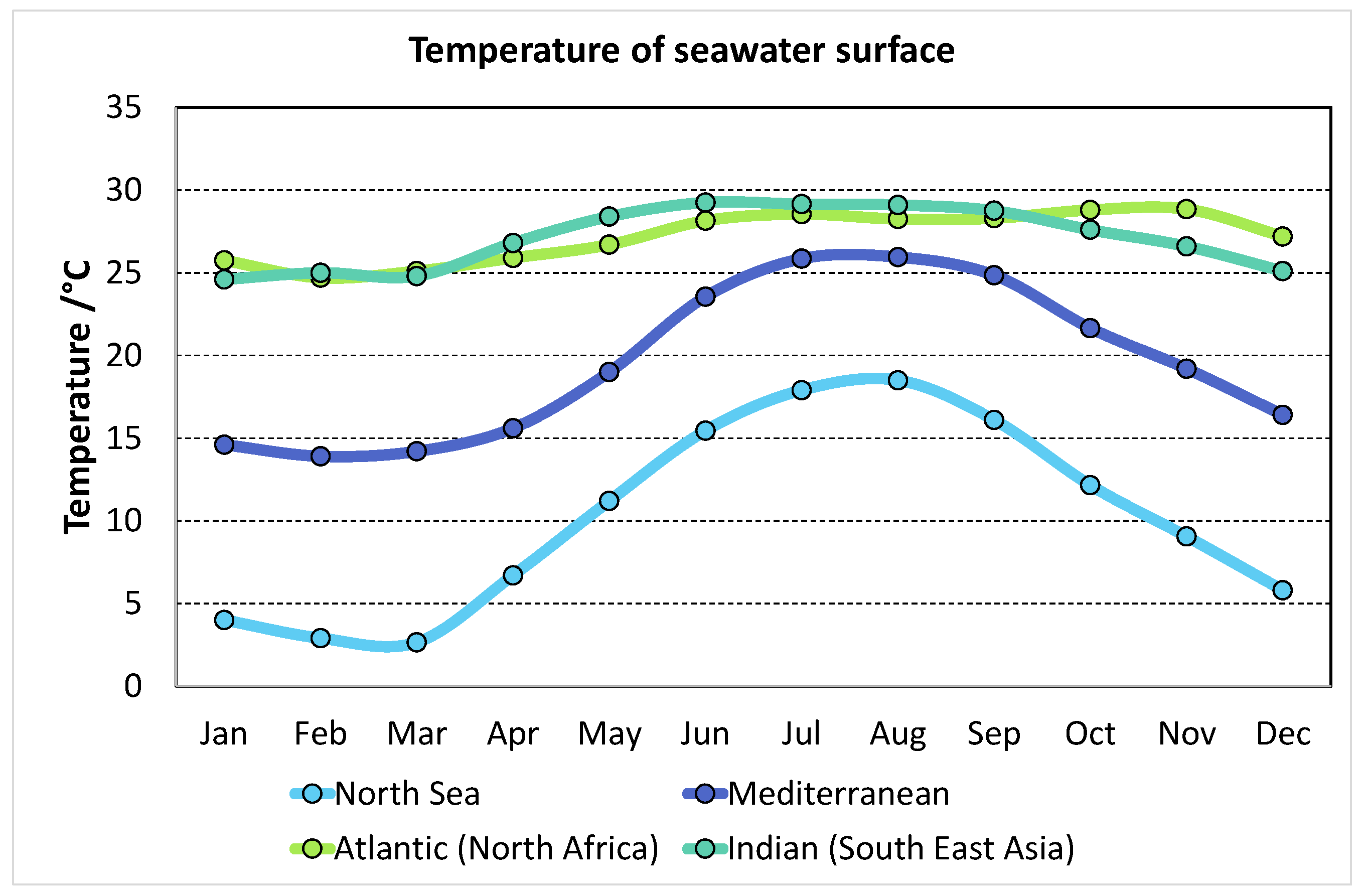
Data from Moderate Resolution Imaging Spectroradiometer (MODIS) sea surface temperature, 8 km Infrared (IR) measurement, from a dataset from 2000 to 2014 [30] were used: the average monthly surface temperature of four areas was obtained, the Mediterranean Sea, the North Sea, the North African coast of the Atlantic Ocean, and the South East coast of the Indian Ocean. The data collected are reported in Figure 2, where it is possible to notice the wide variability of the temperature in the Mediterranean and North Sea, with a maximum difference between summer and winter of about 10 K for the former and almost 18 K for the latter. On the contrary, the temperature profile of the oceans is almost flat, with temperatures in the range 25–28 °C for the entire year. Starting from these values, for simplicity reasons, the dataset was reduced to the design conditions for the refrigeration system reported in Table 2.

3.3. Calculation of Cooling Demand

The cooling demand of a refrigeration system on-board a fishing vessel mainly consists of two contributions: the cooling demand to counterweight the cold room heat losses towards the adjacent rooms and the load for cooling the fish down to a temperature that allows its preservation. The cooling load due to the cold room heat losses can be calculated as:
Q ˙ h e a t   l o s s e s = U A ( T s u r T i n t e r n a l ) ,
where U is the overall heat transfer coefficient of the cold room, considered equal to 0.4 W/m2K, according to the TRNSYS analysis done in [20]; A is the heat exchange area (external area of the cold room); Tsur is the temperature of the surroundings of the cold room, considered equal to Tsur = Tseawater + 5 °C in summer and Tsur = Tseawater − 5 °C in winter [31]; Tinternal is the temperature of the cold room, considered equal to −21 °C. The cold room in all the fishing vessels examined was below the deck and therefore not directly exposed to the external ambient. However, considering that the surroundings of the cold room are rooms that are not conditioned, the assumption of Tsur = Tseawater ± 5 °C can be considered reasonable.
The cooling demand due to the energy needed to freeze the fish in a defined time, tref. is due to three contributions: the sensible heat of the fish to bring it from insertion temperature to the freezing temperature, the latent heat due to the freezing of the fish, and the sensible heat from the freezing point to the temperature of the cold room:
Q ˙ f i s h = M f i s h c p 1 ( T s e a w a t e r T f r e e z i n g ) + λ f r e e z i n g + c p 2 ( T f r e e z i n g T c o l d   r o o m ) t r e f ,
where cp1 is equal to 3.7 kJ/(kgK), cp2 is equal to 2.2 kJ/(kgK), the freezing point Tfreezing is equal to −2.2 °C, and the latent heat released during freezing λ f r e e z i n g is equal to 270 kJ/kg [32], the time needed to freeze the fish, tref, was fixed as 4 h according to [20].
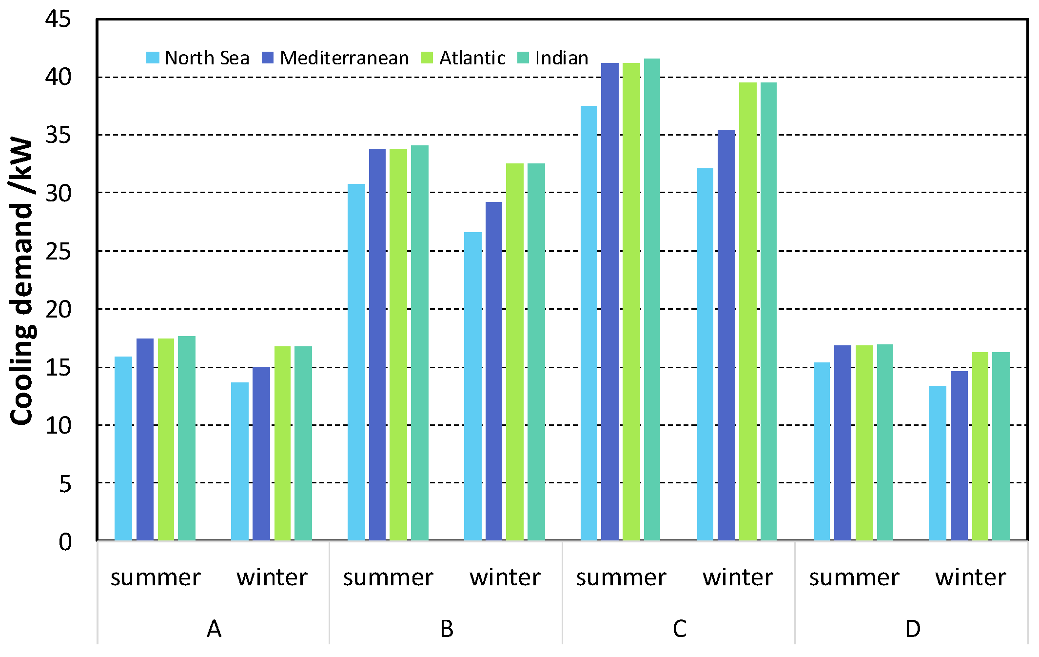
The results, in terms of overall cooling demand for the different fishing vessels typologies (A to D) and operating temperatures, i.e., the four seas/oceans in two seasons, summer and winter, are reported in Figure 3. It can be noted that the cooling demand is specific for each type of vessel rather than the ambient temperature. Indeed, a refrigeration system should be sized for a capacity of about 16 kW in cases A and D, 33 kW in case B, 42 kW in case C. Such values are due to the higher capacity required in the summer but, as previously stated, there is not a relevant difference between the various seasons in the two oceans and the difference in the Mediterranean and North Sea can be considered still within the capacity of regulation of the system.
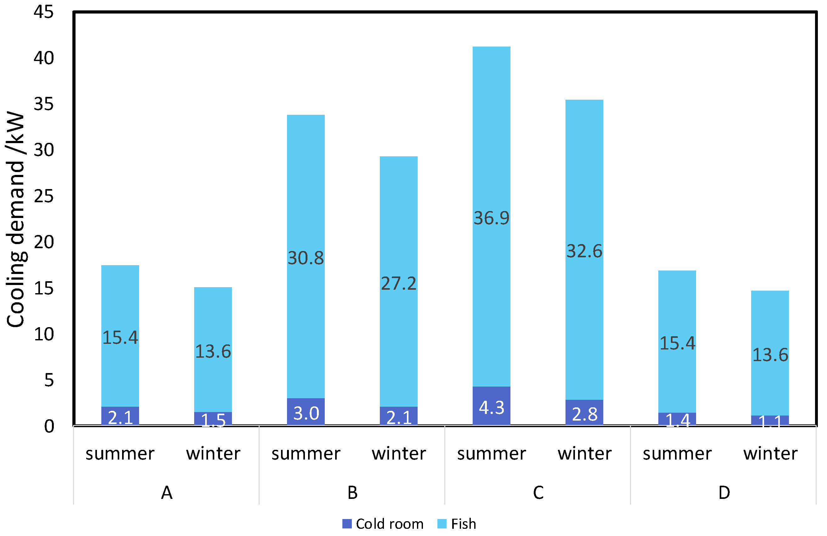
In order to better understand how the various contributions affect the overall cooling demand, the share of power needed for the cold room and for fish refrigeration is shown in Figure 4 for the Mediterranean sea. The contribution of the cold room goes from 1.4 kW for the smaller fishing vessel (case D) to 4.3 kW for case C. During winter, the demand is around 45% lower, going from 1.1 kW to 2.8 kW. The contribution due to the fish caught is the prevalent one, going from 15.4 kW to 37 kW during summer and from 13.6 to 32.6 kW during winter. This indicates that only 10 to 15% of the overall cooling demand is due to the cold room. The reasons for a small effect of external conditions (i.e., seawater temperature and ambient temperature) are linked to the fact that the cold room is below the deck of the vessel, thus not being directly exposed to ambient conditions.

3.4. Available Waste Heat from Engine

The waste heat needed to drive the sorption system should come from the main engine. In particular, depending on the working pair for the sorption system and the layout chosen, heat at different temperatures might be needed. Two main heat sources can, indeed, be employed: waste heat from the exhaust gases, which should be recovered through an economizer, or the cooling water for the engine, which can be recovered thanks to a heat exchanger. Whereas the temperature of the exhaust gases is strongly dependent on the part load ratio (PLR) of the main engine, the temperature of the cooling water is usually constant, between 85 °C and 90 °C [20]. The available waste heat from the exhaust was calculated using the equations reported in [20]. Similarly, the waste heat available from the cooling water was fitted with an equation, on the basis of the data reported in [32]. The fitting equations are:
m ˙ e x h a u s t [ kg h   kW p ] = 6.1943 · P L R + 0.7051 ;
T e x h a u s t [ ° C ] = 443.21   P L R 2 + 745.94   P L R + 117.27 ;
Q c o o l i n g   w a t e r [ kWh kW p ] = 0.1374   P L R + 0.0281 .
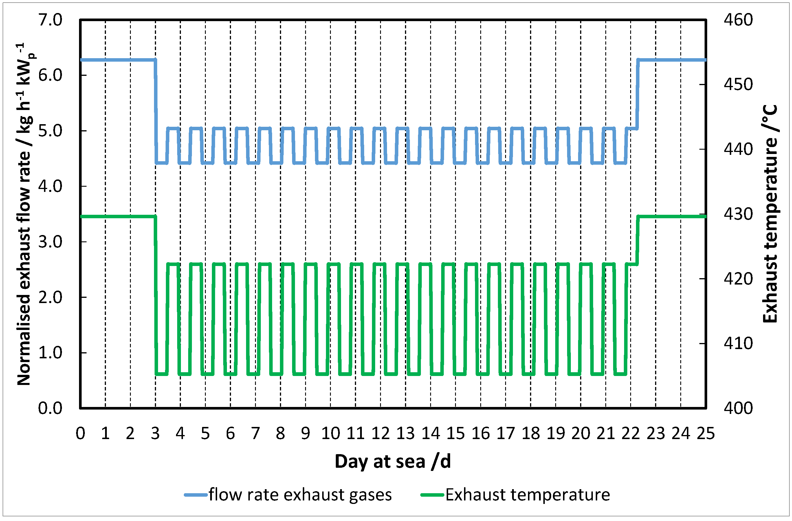
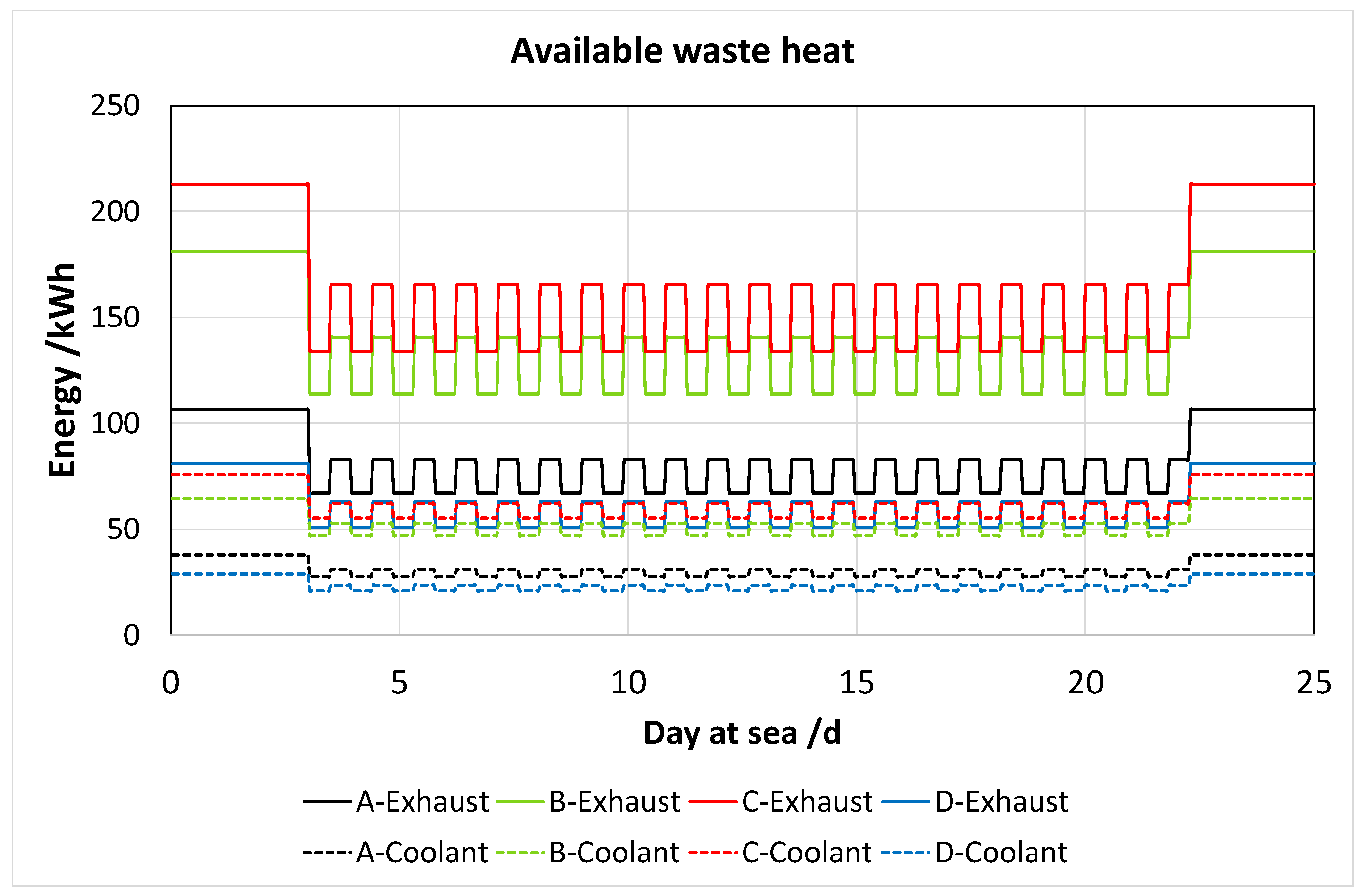
The profile for the route during various days was simplified to the one shown in Figure 5, which reports the calculated exhaust gas temperature and flow rate for the exhaust gases. Compared to the case reported in [33], the simplified route eliminates spikes in the PLR, thus maintaining a safety factor. Starting from such a profile, the waste heat available was calculated, under the following assumptions:
The heat from the exhaust gases is brought at Ttarget = 200 °C;
The heat from the coolant circuit is at 90 °C;
The PLR of the engine, and therefore recoverable waste heat, are constant for each time step of one hour considered in the route profile.
The waste heat recovered from exhausts was calculated as:
Q e x h a u s t = m ˙ e x h a u s t c p e x h a u s t ( T e x h a u s t T t a r g e t ) t s t e p .
Instead, the waste heat from cooling water can be calculated directly from the fitting Equation (6), considering the actual size of the engine on each of the four vessels considered in the analysis.
It needs to be stated that the profiles reported in Figure 5 and Figure 6 are quite regular, with the exceptions of the first and last days at sea. Consequently, as already done in [20], the profile was adjusted to consider the different days of navigation of the fishing vessels, according to what is reported in Table 1.
The waste heat available for all the cases is shown in Figure 6. As can be noted, only less than 25% of heat was the cooling water of the main engine, whereas a higher contribution was given by the exhaust gases. Clearly, the higher amount of waste heat in case C and B was due to the higher size of the engine.

4. The Refrigeration Systems

Currently, the vast majority of on-board refrigeration systems are vapour compression systems employing high-Global Warming Potential (GWP) refrigerants, among which R-22 is still the dominating one [34]. However, such a refrigerant is going into phase out starting from 2020, with a consequent need for suitable replacements. The focus of the present work is to consider not only waste-heat driven sorption systems, as is common in the literature as a replacement for the refrigeration facilities on-board [10], instead, combined systems, which also include compression chillers, are evaluated. The integration of sorption and compression systems is specifically studied to maximise the efficiency of both systems. To achieve this, as will be detailed in the next section, different parallel and series connections were considered.
Regarding sorption systems, different cases were identified, according to the data available in the literature and aiming at representing both commercial or higher technology readiness level (TRL) systems and lab-scale systems at lower TRL. In particular, two sorption systems with the following working pairs were analysed:
  • Activated carbon/ethanol;
  • CaCl2/ammonia.
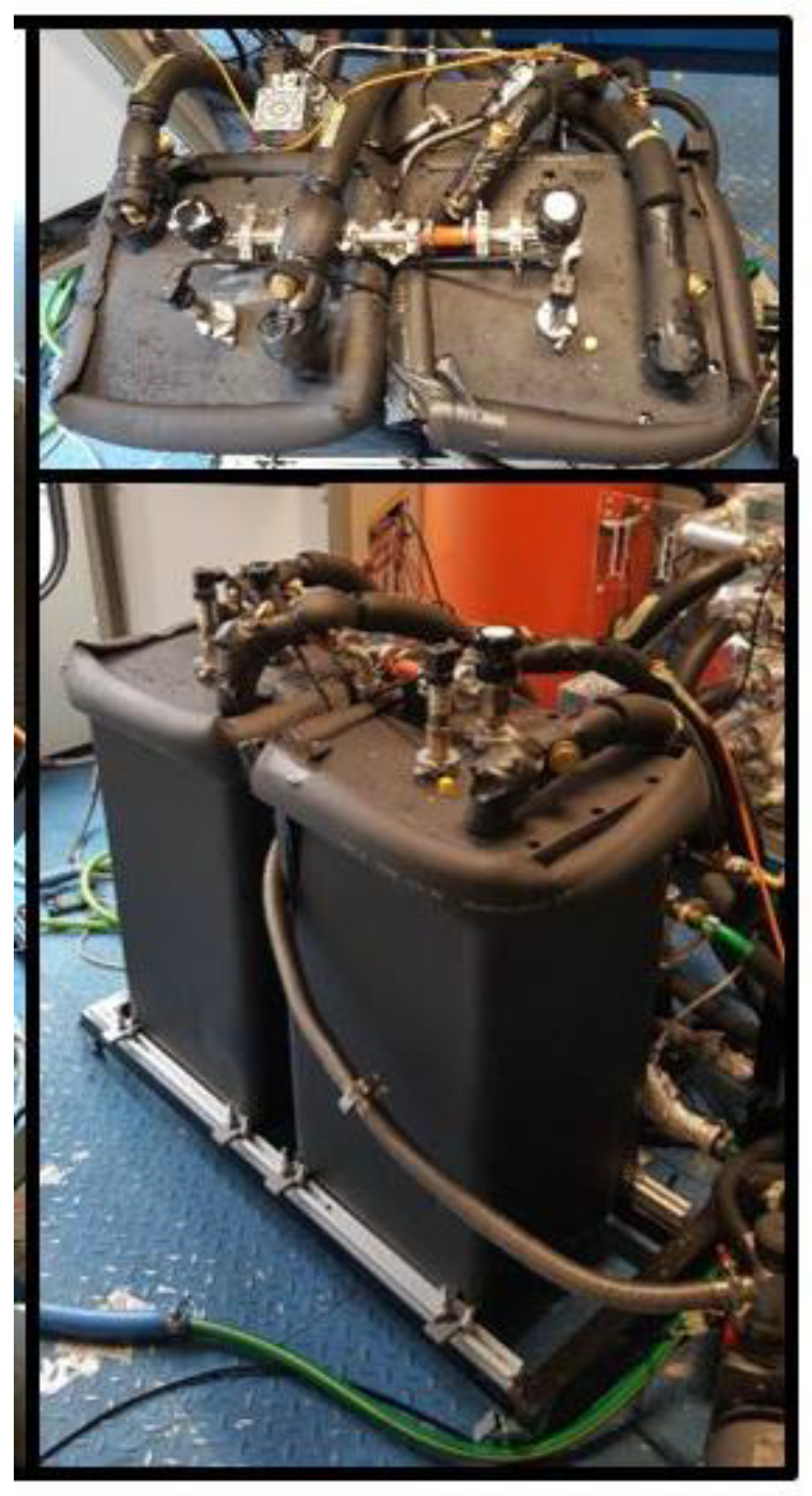
The activated carbon (SRD 1352/3)/ethanol system is the first-ever reported prototype for continuous cooling production employing such a refrigerant. The design of the prototype is presented in [19], whereas its full experimental characterization is reported in [15]. The system was designed for cooling production, in a range of −10 °C to +7 °C, and can be driven by low-grade heat sources, i.e., engine coolant water. The main features of the prototype are reported in Table 3, whereas a picture of the system is shown in Figure 7. The main characteristic of the system is the use of a natural refrigerant (ethanol), with 0 ozone depleting potential (ODP) and very low global warming potential GWP = 6. The system was tested in a lab-scale environment and was then at low TRL, thus the weight and volume that will be used for the subsequent analysis were not optimized and can be subject to a great improvement. Nonetheless, the results reported in [15] indicated the promising potential as a replacement for other systems employing toxic refrigerants, such as methanol. This is especially important for the application in cold rooms, where leakages of the refrigerant can induce safety and health issues on the food preserved.
The second sorption system evaluated was a prototype employing CaCl2 as sorbent and ammonia as refrigerant, whose design and experimental characterization is presented in [16]. Much like water, ammonia is a natural refrigerant with 0 ODP and 0 GWP. The prototype was specifically designed for application in fishing vessels, by paying attention to corrosion issues and realising heat exchangers in such a way that no performance degradation occurs under shaking. In order to improve the Coefficient Of Performance (COP), the cycle includes a four-step heat recovery process. A picture of the system is shown in Figure 8. Despite being a lab-scale system, three different generations with continuous improvement were presented, giving the system a higher TRL than the previous one (TRL 5 versus TRL 4). For the fourth-generation prototype, the estimated volume of the sorption refrigerator is 0.42 m3 and includes a four-step heat recovery system to improve the COP of the unit. This system is composed of a generator, heat exchanger for rectification and distillation, seawater heat exchanger, evaporator, solution heat exchanger, refrigerant heat exchanger, condenser, absorber, pumps, and valves. All the heat exchangers are micro-channel heat exchanger, to improve heat transfer and avoid issues in the flow of the heat transfer fluid due to the shaking of the vessel. A major difference with the activated carbon/ethanol prototype is the possibility of using the system at lower temperatures: evaporation temperatures as low as −20 °C were evaluated. However, the sorption chiller needs to be fed with a heat stream in the range 180–250 °C, and therefore recovery of exhaust gases is needed.
Regarding the compression chiller, for all the configurations that require it, R744 (CO2) was selected as refrigerant; this is the common choice among low-GWP refrigerants in several refrigeration applications, including fishing vessels [34]. In addition, the use of CO2 chillers in cascade configuration with different sorption units has been investigated and the potential benefits proven [35,36]. The characteristics of the CO2 chiller (i.e., volumetric cooling power and Energy Efficiency Ratio, EER) were taken from [37]. Ammonia (R717) could be another alternative refrigerant, thanks to its zero GWP and ODP and the possibility of covering the whole temperature range typical of refrigeration on-board (−40 °C to +10 °C). However, drawbacks of the use of ammonia are the high temperatures reached during compression, the frequent maintenance needed for the compressor, and the risks connected to its toxicity if leakages arise [38]. Regarding CO2 application, it is worth noting that the typical operating conditions at sea, i.e., condensation with seawater, lead to a subcritical CO2 cycle. The great advantage of CO2 over the other refrigerants is the higher volumetric cooling power achievable, with the possibility of reducing the size of the equipment on-board. Indeed, the great efforts in the research and marketisation of CO2 equipment—especially for application in a marine environment—made it possible to have relatively cheap equipment suitable for both subcritical and transcritical CO2 operation [39]. In the present work, only a simple subcritical system was considered, despite the presence on the market of commercial CO2 transcritical equipment or more sophisticated systems (i.e., with parallel compressors). Indeed, those latter systems come with a higher complexity, difficulty in handling the combined operation with the sorption system, and a higher weight, which increases the penalisation in terms of extra fuel to transport the equipment.

5. Integration of Sorption Systems On-board

As pointed out in the introduction and in the previous section, the integration of sorption systems was considered only under the assumption that the waste-heat driven system was the only one providing cooling to the cold room, and only temperature levels from −18 °C to +10 °C were considered, but without any explicit consideration of the refrigeration units installed on-board. Indeed, the features required of the refrigeration system are diverse, depending on the mode of catching fish and the circuit between catch and consumption. When not consumed locally, fish can be processed in different ways: frozen as fresh catch, or fillets, prepared dishes, and canning. Storage and processing methods depend also on the estimated period of preservation: for a short time (from a few hours up to a few days) the fish could be stored in ice flakes or cold rooms, otherwise, freezing preservation is mostly used [34]. Therefore, two main temperature levels are needed: ice production or preservation of fish in cold rooms—between −5 °C and 0 °C and freezing at −40 °C or −21 °C. Hence, it is clear that different sorption systems and, as already discussed, heat sources (i.e., exhaust gases and cooling water of the engine) are needed to optimize the refrigeration process. In the following sections, different cases will be discussed.

5.1. Cascade System

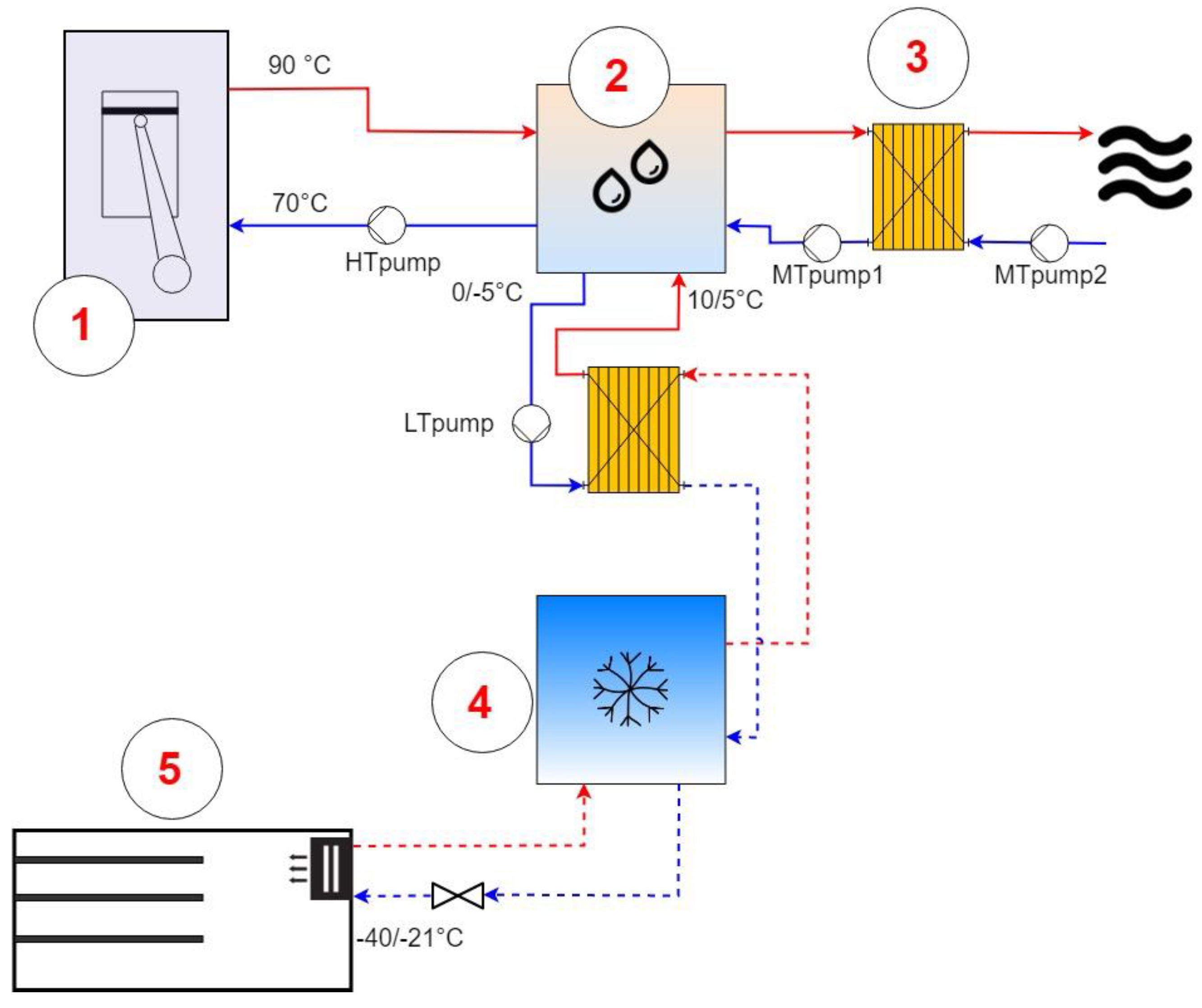
This system is optimized for freezing applications in combination with a plate freezer or direct expansion units. A cascade thermodynamic cycle is performed: a sorption chiller operates as the topping cycle; a vapour compression chiller operates as the bottoming cycle. The sorption chiller, based on the specific technology and working pair chosen, can exploit both 90 °C or 200 °C heat sources and is cooled down by seawater temperature. The useful effect provided at the evaporator is used to cool down the condenser of the vapour compression chiller, thus increasing its EER and reducing the electricity needed. The different temperature lift at the compression unit can even double its efficiency [40]. However, this configuration presents a main drawback, which needs to be carefully evaluated: indeed, each refrigeration unit (i.e., the sorption unit and the compression unit) depends on the other. Consequently, in order to keep the reliability standard, the system should be designed so that the compression unit is able to work directly in connection with the seawater Heat Exchanger (HEX) or so that a back-up unit exists. The main components and schematic layout of such a configuration are shown in Figure 9. Cascade units combining sorption and compression chillers have been widely studied, both for the case of the silica gel/water or ammonia/water and water/LiBr [40]. This configuration is suitable for all systems, with one main difference: if the top sorption cycle makes use of a working pair that can go below 0 °C (i.e., exploiting ammonia as refrigerant), the temperature lift in the compression unit can be further reduced.
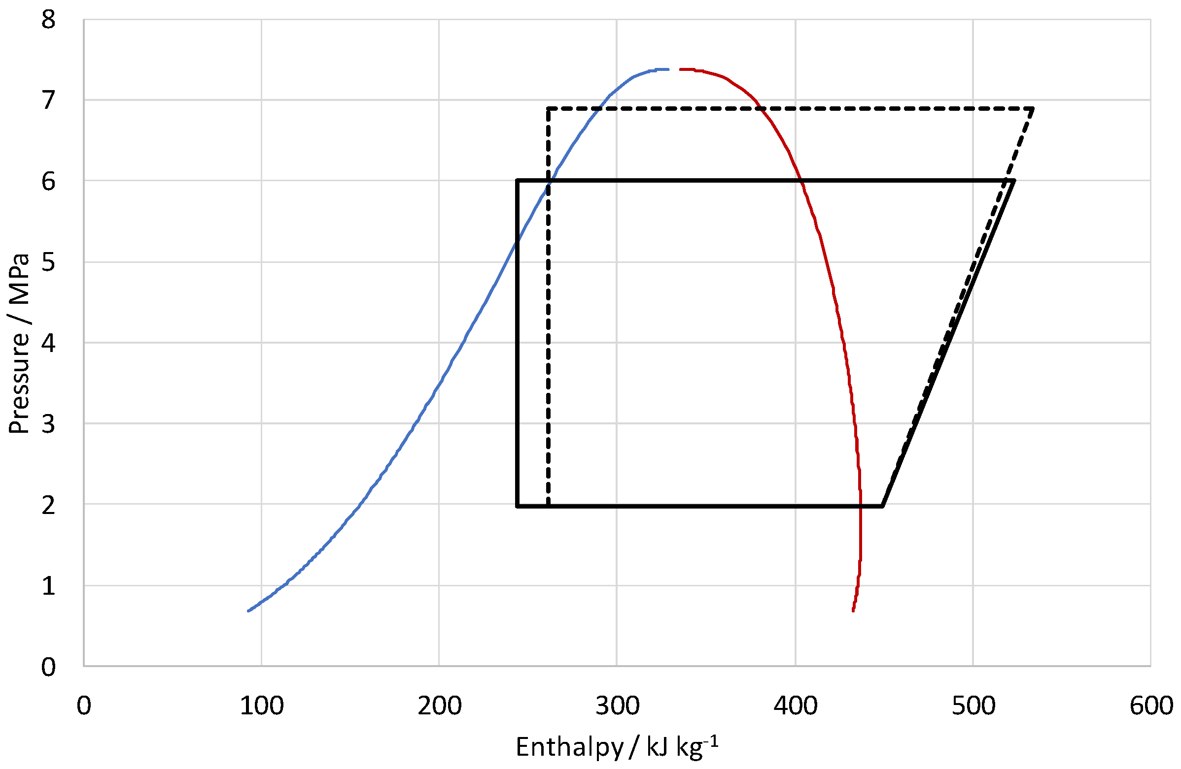
The benefits of the use of such a hybrid system over the reference compression system as stand-alone can be seen in the comparison of the thermodynamic cycle for the compression chiller in the two operating modes in Figure 10. It can be seen here that the operation of as cascade makes it possible to greatly reduce the temperature lift, thanks to the reduction in the condensation temperature—and therefore the work required by the compressor.

5.2. Cascade System with Pre-Conditioning

In several applications, there is a contemporary need to freeze the fish and store it at a temperature level between −5 °C and 0 °C. In addition, as will be discussed in the next section, the heat available on-board is often in excess with respect to the needs of a sorption unit. It is then possible to exploit this situation using a cascade system with pre-conditioning, as shown in the schematics of Figure 11. This system is similar to the former one, since it is based on a cascade cycle with the sorption unit as top cycle and the compression unit as bottom cycle, but it includes an extra component, i.e., a pre-conditioning unit. This consists of a heat exchanger that exploits a fraction of the cooling production of the sorption machine, to cool down the fish from seawater temperature to −5 °C/0 °C. The fish can then be sent to the storage room or introduced into the cold room for refrigeration, thus increasing the overall efficiency of the system, in order to reduce the load that the compression chiller has to cover, also reducing the temperature drop to which the fish is subjected. Similar to the previous case, the system can work with variable temperature range according to the working pair and technology applied. However, with respect to the cascade system, the sorption unit should be oversized, in order to be able to cover part of the cooling load directly, and an extra HEX is needed (pre-conditioning unit, 6 in Figure 11).

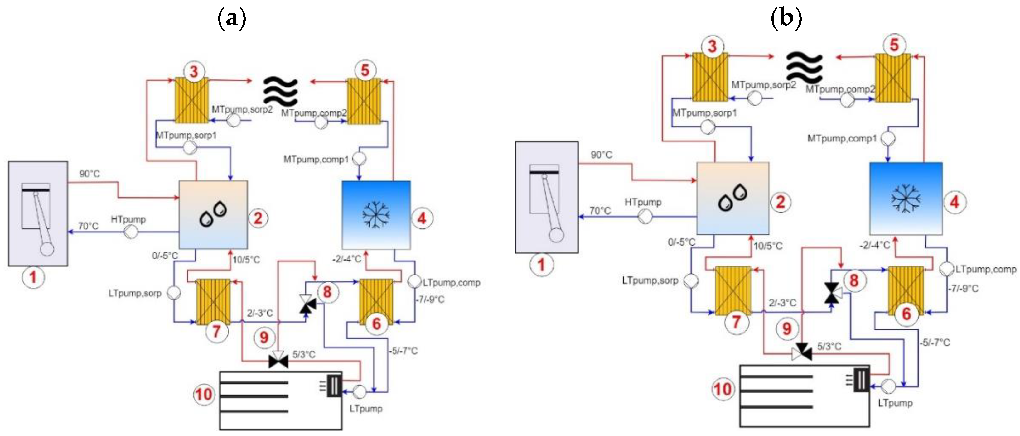
5.3. Series Hybrid System

The application of hybrid systems for covering air conditioning loads is becoming more and more common [36,41,42]. They can be arranged in a cascade way, as for the systems previously described, or working in series and thus exploiting the main advantages of each of the two units in the hybrid chiller. In order to maximize the efficiency in covering the cooling demand, when temperatures slightly below 0 °C are required (i.e., −3/−10 °C), it is possible to combine the two technologies. The possible configuration is shown in Figure 12: a sorption unit is provided for the baseload request, and a vapour compressor one for peaks. When they operate in combination, chilled brine flows, at first, through the evaporator of the sorption chiller and subsequently through the evaporator of the vapour compression chiller. In this way, it is cooled in two steps and the energy demand is shared between the two chillers. Contrary to the hybrid cascade configuration, in this case it is possible to operate the units separately, thanks to the three-way valve shown in the schematics. The temperature levels at which the chiller operates are strongly dependent on the working pair chosen and the demand on-board. Compared to the case of the cascade chiller, the sorption unit might be smaller, thus reducing the overall volume needed for installation. However, the efficiency of the compression unit is lower since it operates with higher temperature lifts, making the system suitable only when peaks in the cooling demand occur less often. In this case, indeed, contrary to the previous one, the compression cycle is not changed, only the cooling load that the compression chiller has to supply is reduced.

5.4. Feasibility Evaluation of Integrated Configurations

The evaluation of a specific solution among the proposed ones is strongly dependent on different constraints. Indeed, the installation of the systems previously described might need additional volume compared to traditional solutions. Furthermore, such systems are usually heavy and therefore might lead to a penalization in the fuel consumption during shipping. As a pre-feasibility screening parameter, the possibility of driving the sorption system totally with the waste heat from engines was evaluated. In order to reduce the penalisations due to the sorption units on-board, it is of paramount importance that there is no need for integration of the driving heat source. For the critical analysis, it was assumed that the system works in steady-state conditions, i.e., the heat source temperature, seawater temperature, and user-side temperature are constant.
The boundary conditions for each configuration, in terms of temperature levels and efficiency of the sorption and compression units, are shown in Table 4 and Table 5.
In the evaluation of the performance of the sorption systems, the following parameters were employed:
-
Thermal COP, the ratio between the cooling energy delivered and the driving heat needed:
C O P = Q c o o l Q h e a t .
-
EER (energy efficiency ratio), the ratio of the cooling energy delivered over the electricity needed to drive auxiliaries:
E E R s o r p t i o n = Q c o o l E .
-
The SCP (specific cooling power), i.e., the normalized cooling power per unit of sorbent that the chiller can deliver:
S C P = Q c o o l m s o r b .
As previously stated, the preliminary condition to be fulfilled by each configuration is the possibility of relying only on waste heat from the engine for driving the sorption cycle. To achieve this, the number of hours, over the total, during which the integrated systems presented can be driven by the waste heat from the engine in each case are presented in Table 6.
As can be seen, due to the low COP of the AC/ethanol system, application on bigger size vessels (vessel B and C) is possible only in the North Sea, where seawater temperatures are lower and the efficiency of the system is higher. On the contrary, the system can be applied in medium size vessels (type A), for all routes worldwide. For fishing vessel D, i.e., the smaller vessel among the examined ones, even though the cooling load is lower, since the engine is also smaller, the amount of waste heat is still insufficient to drive the system. On the contrary, the CaCl2/ammonia system is suitable for all the examined conditions, since it can be run by waste heat in each case.
Considering the outcome of this feasibility analysis, a more detailed energy and environmental analysis will be presented in the following section, based on some typical cases:
  • The use of the AC/ethanol system for fishing vessel A in the Indian Ocean (since this is the most critical condition, due to the higher temperature of the water) and in vessel C in the North Sea for series configuration;
  • The use of the CaCl2/ammonia system for cascade configuration, for all vessels in the North Sea and Indian Ocean conditions.
It is important to note that the activated carbon/ethanol prototype is the very first system presented in the literature of a sorption system with ethanol as refrigerant to work with continuous cooling effect. Its design is therefore far from optimized, in the design of the system itself (for instance, in a real system cylindrical vacuum vessels with much lower weight and exposed surface could be used instead of parallelepipedal ones) and in the size (scaling of weight and volume is not linear with size [20]). A real full-scale system would be characterized by (1) higher COP; (2) higher SCP; (3) much lower need for waste heat. This means that the present analysis can significantly underestimate the benefits arising from the use of such a technology, further stressing that the positive results obtained can be further enhanced.

6. Energy Analysis

6.1. Cascade Configuration

Cascade configuration of sorption chillers presents the great advantage of combining the benefits of a sorption system and a compression system: whereas a sorption system works in a discontinuous way, a compression system has a fast and precise response to load variations [40]. Such an aspect is more important for food refrigeration than in other applications: in order for the fish to be correctly preserved, it needs to reach at least −20 °C in less than 4 h, not only on the surface, but also deep in the core. Therefore, a quick adaptation to the load is of crucial importance. On the other hand, the sorption chiller presents a reduced electricity need—only for the auxiliaries. The cascade system was sized so that the cooling power output of the sorption chiller matches the condensation power for the compression chiller:
Q ˙ e v s o r p = Q ˙ c o n d c o m p .
Considering the heat balance on a compression chiller, the condensation heat is equal to the cooling power and the energy input for the compressor:
P e l c o m p = Q ˙ e v c o m p E E R c o m p r e s s i o n .
It follows:
Q ˙ e v s o r p = Q ˙ e v c o m p ( 1 + 1 E E R c o m p r e s s i o n ) .
For vessel A, the size for the North Sea and Indian Ocean was 20 kW and 22 kW, respectively; for vessel B, the size of the sorption system needed was 36 kW in the North Sea and 40 kW in the Indian Ocean; for vessel C it was 38 kW and 45 kW for the North Sea and Indian Ocean; whereas for vessel D it was 22 kW in the North Sea and 26 kW in the Indian Ocean.
The overall utilization of the waste heat from the engine, i.e., the fraction of waste heat needed to drive the cascade system is shown in Figure 13. As can be seen, only a small fraction of the overall heat from exhaust gases at 200 °C was used: for vessel D, where the amount of waste heat needed was the lowest, the maximum utilized fraction was 50%, whereas for the bigger vessels B and C, no more than 22% of waste heat was needed.
The energy savings EES with respect to the reference system, i.e., the R744 chiller that covers the whole cooling demand, can be calculated as:
E E S = E r e f e r e n c e E c a s c a d e .
The electricity consumption of the reference system can be calculated as:
E r e f e r e n c e = E c o m p r e s s o r + E L T p u m p + E M T p u m p 1 + E M T p u m p 2 .
This includes the electricity consumption for the operation of the compressor and the auxiliaries, i.e., the pump in the chilled brine (evaporator, LTpump) circuit and the pumps of the cooling (condenser, MTpump1 and MTpump2) circuit.
The electricity consumption of the cascade system includes not only the electricity consumption of the compressor and the pumps of the compression unit, but also the pumps of the sorption unit, for the heat source (HTpump) circuit, cooling seawater (MTpump1 and MTpump2) circuit, and chilled brine (LTpump) circuit:
E c a s c a d e = E c o m p r e s s o r + E L T p u m p + E M T p u m p 1 + E M T p u m p 2 + E H T p u m p .
In order to define the electricity consumption of the auxiliaries, the outcomes of the experimental activity on different sorption and cascade systems at CNR were used [40,43], by defining suitable scaling factors for the electricity consumption of the auxiliaries, reported in Table 7 [20].
In addition, the fuel savings due to the operation of the cascade system can be calculated considering that electricity generation on-board is obtained through a generator connected to the main engine:
F S = E E S η g e n L H V f u e l ,
where the efficiency of the generator considered is 50% and the low heating value (LHV) of the fuel is 0.004878 kWh/g [20].
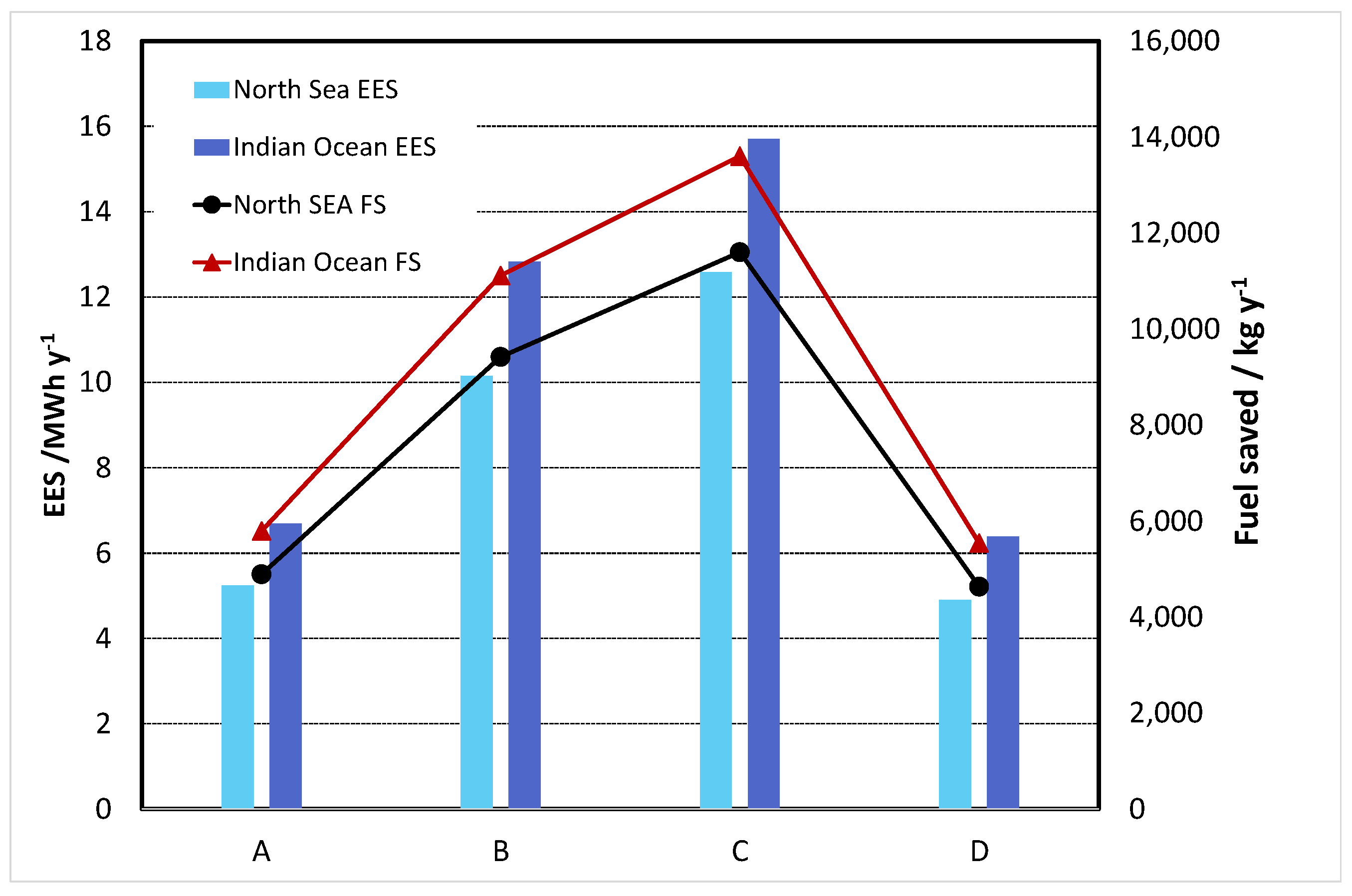
The results are shown in Figure 14, where both energy savings and fuel saved for the various cases are reported. The energy savings were more consistent in the Indian Ocean, due to the higher seawater temperature and therefore the greater advantage in employing cascade configuration over the reference system. They varied between 6.8 MWh/y for vessels A and D and 13 MWh/y for vessel B, up to a maximum of 15.7 MWh/y for vessel C. For the North Sea, the energy savings were around 15% lower. For all cases, the energy saved amounted to 33 to 35% of the overall energy consumption of the reference system. Fuel saved varied correspondingly between 5000 kg/y up to 14,000 kg/y for vessel C in the North Sea and 8500 kg/y for vessel C in the Indian Ocean. It is worth stating that the lower energy required from the main generator, due to the reduction in the consumption for refrigeration, can be used for other auxiliaries, thus eliminating—or limiting—the need for secondary generators, without reducing the PLR of the engine.
The energy savings, and therefore fuel savings, were normalised with respect to the energy (and fuel) requested for the reference system. The results of the calculations are reported in Table 8. As can be seen, an energy reduction of more than 70% for the refrigeration system was obtained by replacing the system with the combined sorption–compression one. Such savings correspond to a reduction of 4–6% of the overall energy consumption of the engine, thus representing an important contribution towards the overall efficiency of the ship.
The volume needed for the installation of the overall system (sorption + compression) for the different cases was calculated as well and is shown in Table 9. For the smaller vessels (A and D), the volume needed for the installation was between 1.2 m3 and 1.5 m3, whereas for the bigger ones (B and C) a volume from 2.4 m3 up to 3.4 m3 was needed. For comparison, Table 9 reports also the volume needed for the installation in case of the use of a CO2 compression chiller to cover the whole load. As can be seen, the penalisation, in terms of volume needed for the installation, is quite high, from 500% up to 700%, and therefore it represents an issue to be carefully addressed. It is, however, worth noticing that the system considered is still an unoptimized lab-scale prototype and scaling it up for real installation might significantly reduce the dead volume and therefore increase the volumetric cooling power. The volume needed for the sorption system was calculated, starting from the volumetric cooling power of the two systems, in kW/m3, reported in the literature references [16] and [19], while the volume needed for the R744 chiller was taken from the volumetric cooling power of the compression chiller reported in reference [37].
There is another penalisation due to the utilization of the sorption cascade system over the reference one: the overall weight of the cascade system and waste heat recovery exchanger is higher than the reference system and this could negatively affect the fuel consumption of the fishing vessel. To estimate such an effect, the approach described in [22] and already applied in [20] was followed: the extra power needed from the engine for the transportation of the extra weight was calculated as:
P c a s c a d e P r e f e r e n c e = ( 1 + Δ c a s c a d e Δ r e f e r e n c e Δ r e f e r e n c e ) 2 / 3 ,
where Δ c a s c a d e and Δ r e f e r e n c e are the mass displacement in metric tons, which includes the tonnage of the ship and the refrigeration system.
The different mass displacement of the vessel with the cascade was calculated by taking into account the specific weight of the sorption system, taken from [16], as well as for the auxiliaries and the waste heat recovery system, taken from [20]. For the fishing vessel and its engine, data in Table 1 were used. Once the extra power needed was calculated, the extra fuel was calculated, considering a fuel consumption of 205 g/kWh [16]. The results for the Indian Ocean and North Sea were the same, since the term Δ c a s c a d e Δ r e f e r e n c e Δ r e f e r e n c e was equal in both cases, and were as follows: for vessel A, the extra fuel needed was 280 kg/y, for vessels B and C 305 kg/y, and for vessel D 301 kg/y. Considering the results of Figure 14, it is evident that the extra penalisation was lower than 10% of the overall fuel savings, and therefore less than 1% on the overall fuel consumption of the vessel, thus highlighting the benefits of the use of the waste-heat powered system.

6.2. Series Configuration

The second configuration considered was series configuration, for two different temperatures and fishing vessels tonnage, i.e., the small fishing vessel A in the North Sea and the bigger fishing vessel C in the Indian Ocean, which represents the worst case, in terms of temperatures and cooling load. One of the parameters that can be optimized in the series configuration is the amount of cooling load that each unit can provide. For the present case, according to the temperature levels and schematics presented in Figure 12, the AC carbon/ethanol prototype was sized to cover 70% of the overall cooling load, i.e., the base load needed to bring the fish to a temperature of 2/3 °C, while the remaining load was provided by the compression chiller. The overall system was a water/water system, meaning that the heat transfer fluid in all circuits was brine (i.e., water/glycol mixture), different from the cascade configuration previously analysed. Indeed, it is intended for refrigeration and storage of fish that require higher temperatures, i.e., −5 °C to −10 °C.
At first, the fraction of waste heat used was calculated: for fishing vessel A in the Indian Ocean it was about 90% of the overall heat from the cooling circuit of the engine, whereas for vessel C in the North Sea it was 70% of the overall heat available from exhaust gases. In the latter case, indeed, the heat from the cooling circuit of the prime mover was too low to power the sorption system and therefore the installation of a waste heat recovery heat exchanger was considered.
The results of the energy analysis on the series configuration are reported in Table 10. Compared to the case of cascade configuration, the energy savings were significantly higher, i.e., 71–73% against 33%. This is due to different features linked to the operation of the system: on the one hand, a relevant fraction of the load was covered by the sorption system, with a reduced electricity consumption due to the auxiliaries only; on the other hand, the temperature lifts for the units were quite different. It can be seen that, for the examined cases, the fuel savings were double the ones reported in Figure 14. On the contrary, as previously discussed, there are some limitations in the installation of such a sorption system, since it is not suitable for all conditions due to the higher evaporation temperatures for the proper operation. Moreover, when considering the activated carbon/ethanol working pair, due to the high amount of heat needed, not all the examined conditions are feasible. Such a restriction, instead, does not apply for the CaCl2/ammonia system.
The volume needed for the installation was calculated as well: 0.8 m3 was needed for vessel A in Indian Ocean conditions and 1.6 m3 for vessel C in North Sea conditions. The reference system, i.e., the R744 compression chiller that covered the whole load, required instead 0.3 m3 in vessel A the for Indian Ocean and 0.7 m3 for vessel C in the North Sea. Compared to the previous case, the difference between the waste-heat powered system and the reference one was lower, due to the fact that, in this case, the sorption system was undersized compared to the overall load (which was, in turn, lower, due to the higher storage temperatures). On the contrary, in the cascade system, the sorption chiller was sized to cover the condensation heat of the compression system and was then sized for about 130% of the cooling demand.
Finally, the payload analysis to calculate the incidence of the extra weight of the system was carried out, using the approach described in the previous section. The results are similar to those reported for the cascade configuration, i.e., an extra amount of fuel of 420 kg/y for the vessel A in the Indian Ocean and 470 kg/y for vessel C in the North Sea. Such an amount is about 5% of the overall fuel savings, thus not altering the convenience in the installation of such a system.

7. Environmental Analysis

The CO2 emissions avoided were calculated, taking into account lower electricity consumption of the waste-heat powered system, as:
Δ C O 2 = C O 2 , reference C O 2 , c a s c a d e = E E S η C O 2 .
The CO2 emission factor η C O 2 was considered equal to 1.3 tCO2/tfuel [20].
The results are reported in Table 11. The CO2 emissions avoided were higher for the series configuration, due to the reduced size of the compression chiller, and varied between 4 and 11 t/y for the cascade configuration, with higher emissions avoided in the Indian Ocean, where the operation of the reference system was penalised by the higher water temperatures.
From the results reported in this section and the previous one, it is possible to state that both systems analysed have potential. They are meant for different applications, since the cascade configuration is intended for cases where sub-zero refrigeration, with expansion systems as cold distribution systems in the cold room, is required. On the contrary, the series configuration is intended for fresh fish storage at temperatures in the range of +2–5 °C. The aim of the analysis was to confirm the possibility of using hybrid sorption–compression systems in on-board conditions for different applications and showed the feasibility of both. Indeed, considering also the great amount of waste heat available on-board, especially in bigger trawlers, and the low penalisation in terms of extra fuel to transport the heavier hybrid system, a combined application of both systems analysed can be foreseen, in the case of contemporary cold demand at sub-zero and above zero.

8. Future Trends and Alternatives

The results reported in the previous sections highlight the good potential of the solution described, which allows a significant reduction in the fuel consumption of fishing vessels, with a clear benefit in terms of the sustainability of the shipping sector. This is a crucial point, especially considering the stringent international laws in terms of energy efficiency in the shipping sector [44] and the legally-binding measures adopted within MARPOL Annex VI for the reduction of greenhouse gas (GHG) emissions from international shipping [3], which set a 10% reduction with progressive tightening of the target every five years. The introduction of alternative refrigeration systems can then represent an important step forward, considering that refrigeration demand represents more than 40% of the energy demand in long-distance non-touristic shipping [22,45]. However, further optimization is possible, for example, combining the waste-heat powered system with other alternative systems for air-conditioning and domestic hot water production or the extension of such systems also to cruise ships. For instance, in [5], the energy and exergy analysis for a cruise ship in the Baltic Sea indicated that around 30% of the energy demand of the ship is due to space heating, with several inefficiencies in the boilers used for providing such a demand. The authors also suggested that an even higher share of energy demand could be encountered in cruise ships operating in warm climates, due to the electricity needed for the chillers that cover cooling demand. It is clear that the solutions proposed could be even more beneficial in these cases, thanks to the intrinsically higher efficiency of the sorption system at higher evaporation temperatures (+5 °C to +15 °C for air conditioning purposes). For example, for the system proposed in [21], a volumetric cooling power up to 275 kW/m3 was measured, which would also significantly reduce the space needed for installation, without any limitation due to the volume of the technical rooms. For the case of a chemical tank, waste heat recovery for covering heating demand could lower the fuel consumption up to 18% [46]. In this case, the application of a sorption system is even more interesting, due to the efficiency higher than 1 when operating as a heat pump.
Further improvements of the system, however, do not only rely on a sorption system for heating and cooling. As reported in the previous analysis, even using sorption or hybrid sorption–compression systems, there is a significant amount of waste heat still potentially unused that can be recovered from exhaust gases. A promising application could be the integration of an ORC system for the production of electricity needed for the ancillary systems or for the chillers and auxiliaries of the heating, cooling, and refrigeration system. An analysis of a cruise ship in the North Sea indicated that up to 22% of the electricity demand could be covered by waste heat [46]. Moreover, the comparative analysis of different power cycles in [46] indicated the ORC solution as a promising alternative due to the simplicity in the layout and the possibility of using non-toxic refrigerants. For example, for the cases examined, considering the waste heat available that is not used by the refrigeration system and an efficiency of the ORC of 5% (which can instead be significantly improved), up to 20 kW of electricity might be produced, even higher than the electricity demand needed for the refrigeration system itself, which could be then totally sustainable with waste heat.
Another aspect to be considered is the time mismatch and oscillations in the heat source and cooling load. An efficient way to cover this issue is the development of thermal energy storages with high density. Up to now, there are no reports on the use of such systems, i.e., thermal energy storages with Phase Change Materials (PCMs) or thermochemical systems on-board, but a prototype specifically developed for application on cruise ships is presented in [47], highlighting the challenges and promising possibilities even under severe ambient and operating conditions.
From such an analysis it is clear that the challenge for a sustainable shipping sector might also be addressed and implemented successfully in the existing fleet. It must certainly be acknowledged that, due to the wide variability of operating conditions, energy demand and heterogeneous routes of the ships, the evaluation and optimization should take into account the peculiarity of each ship. Nonetheless, the critical analysis presented can improve the exploitation of all the energy flows for efficient generation, conversion, and storage on-board, toward a less energy-intensive shipping sector for the coming years.

Author Contributions

Conceptualization, V.P. and G.E.D.; Data curation, V.P. and G.E.D.; Formal analysis, C.M.; Funding acquisition, A.F.; Supervision, R.G. and A.F.; Writing—original draft, V.P.; Writing—review and editing, G.E.D., R.G., C.M. and A.F.

Funding

This work was carried out in the frame of a joint bilateral Malta-Italy project of the University of Malta and the CNR (CUP: B46C18000400001).

Conflicts of Interest

The authors declare no conflict of interest.

References and Note

  1. IMO Third IMO GHG Study. Available online: http://www.imo.org/en/OurWork/Environment/PollutionPrevention/AirPollution/Pages/Greenhouse-Gas-Studies-2014.aspx (accessed on 19 September 2019).
  2. Thomas, G.; O’Doherty, D.; Sterling, D.; Chin, C. Energy audit of fishing vessels. Proc. Inst. Mech. Eng. Part M J. Eng. Marit. Environ. 2010, 224, 87–101. [Google Scholar] [CrossRef]
  3. IMO Energy Efficiency Measures. Available online: http://www.imo.org/en/OurWork/Environment/PollutionPrevention/AirPollution/Pages/Technical-and-Operational-Measures.aspx (accessed on 19 September 2019).
  4. Bouman, E.A.; Lindstad, E.; Rialland, A.I.; Strømman, A.H. State-of-the-art technologies, measures, and potential for reducing GHG emissions from shipping—A review. Transp. Res. Part D Transp. Environ. 2017, 52, 408–421. [Google Scholar] [CrossRef]
  5. Baldi, F.; Ahlgren, F.; Nguyen, T.-V.; Thern, M.; Andersson, K. Energy and Exergy Analysis of a Cruise Ship. Energies 2018, 11, 2508. [Google Scholar] [CrossRef]
  6. Ancona, M.A.; Baldi, F.; Bianchi, M.; Branchini, L.; Melino, F.; Peretto, A.; Rosati, J. Efficiency improvement on a cruise ship: Load allocation optimization. Energy Convers. Manag. 2018, 164, 42–58. [Google Scholar] [CrossRef]
  7. Larsen, U.; Sigthorsson, O.; Haglind, F. A comparison of advanced heat recovery power cycles in a combined cycle for large ships. Energy 2014, 74, 260–268. [Google Scholar] [CrossRef]
  8. Shu, G.; Liang, Y.; Wei, H.; Tian, H.; Zhao, J.; Liu, L. A review of waste heat recovery on two-stroke IC engine aboard ships. Renew. Sustain. Energy Rev. 2013, 19, 385–401. [Google Scholar] [CrossRef]
  9. Parker, R.W.R.; Tyedmers, P.H. Fuel consumption of global fishing fleets: Current understanding and knowledge gaps. Fish Fish. 2015, 16, 684–696. [Google Scholar] [CrossRef]
  10. Xu, X.; Li, Y.; Yang, S.; Chen, G. A review of fishing vessel refrigeration systems driven by exhaust heat from engines. Appl. Energy 2017, 203, 657–676. [Google Scholar] [CrossRef]
  11. Wang, R.Z. Efficient adsorption refrigerators integrated with heat pipes. Appl. Therm. Eng. 2008, 28, 317–326. [Google Scholar] [CrossRef]
  12. Gullì, G.; Sapienza, A.; Caprì, A.; Costa, F.; La Rosa, D.; Palomba, V.; Freni, A. Innovative adsorption chiller for marine applications: Design and building. Energy Procedia 2015, 82, 432–438. [Google Scholar] [CrossRef]
  13. Ge, Z.; Li, J.; Duan, Y.; Yang, Z.; Xie, Z. Thermodynamic Performance Analyses and Optimization of Dual-Loop Organic Rankine Cycles for Internal Combustion Engine Waste Heat Recovery. Appl. Sci. 2019, 9, 680. [Google Scholar] [CrossRef]
  14. Cao, T.; Lee, H.; Hwang, Y.; Radermacher, R.; Chun, H.-H. Performance investigation of engine waste heat powered absorption cycle cooling system for shipboard applications. Appl. Therm. Eng. 2015, 90, 820–830. [Google Scholar] [CrossRef]
  15. Palomba, V.; Dawoud, B.; Sapienza, A.; Vasta, S.; Frazzica, A. On the impact of different management strategies on the performance of a two-bed activated carbon/ethanol refrigerator: An experimental study. Energy Convers. Manag. 2017, 142, 322–333. [Google Scholar] [CrossRef]
  16. Lu, Z.; Wang, R. Experimental performance study of sorption refrigerators driven by waste gases from fishing vessels diesel engine. Appl. Energy 2016, 174, 224–231. [Google Scholar] [CrossRef]
  17. Salmi, W.; Vanttola, J.; Elg, M.; Kuosa, M.; Lahdelma, R. Using waste heat of ship as energy source for an absorption refrigeration system. Appl. Therm. Eng. 2017, 115, 501–516. [Google Scholar] [CrossRef]
  18. Sapienza, A.; Gullì, G.; Calabrese, L.; Palomba, V.; Frazzica, A.; Brancato, V.; La Rosa, D.; Vasta, S.; Freni, A.; Bonaccorsi, L.; et al. An innovative adsorptive chiller prototype based on 3 hybrid coated/granular adsorbers. Appl. Energy 2016, 179, 929–938. [Google Scholar] [CrossRef]
  19. Frazzica, A.; Palomba, V.; Dawoud, B.; Gullì, G.; Brancato, V.; Sapienza, A.; Vasta, S.; Freni, A.; Costa, F.; Restuccia, G. Design, realization and testing of an adsorption refrigerator based on activated carbon/ethanol working pair. Appl. Energy 2016, 174, 15–24. [Google Scholar] [CrossRef]
  20. Palomba, V.; Aprile, M.; Motta, M.; Vasta, S. Study of sorption systems for application on low-emission fishing vessels. Energy 2017, 134, 554–565. [Google Scholar] [CrossRef]
  21. Sapienza, A.; Palomba, V.; Gullì, G.; Frazzica, A.; Vasta, S. A new management strategy based on the reallocation of ads-/desorption times: Experimental operation of a full-scale 3 beds adsorption chiller. Appl. Energy 2017, 205, 1081–1090. [Google Scholar] [CrossRef]
  22. Cao, T.; Lee, H.; Hwang, Y.; Radermacher, R.; Chun, H.-H. Modeling of waste heat powered energy system for container ships. Energy 2016, 106, 408–421. [Google Scholar] [CrossRef]
  23. Palomba, V.; Aprile, M.; Vasta, S.; Gullì, G.; Freni, A.; Motta, M. Study and Evaluation of Two Innovative Waste-heat Driven Refrigeration Systems for Fishing Vessels Applications. Energy Procedia 2016, 101, 838–845. [Google Scholar] [CrossRef]
  24. Maeda, S.; Thu, K.; Maruyama, T.; Miyazaki, T. Critical Review on the Developments and Future Aspects of Adsorption Heat Pumps for Automobile Air Conditioning. Appl. Sci. 2018, 8, 2061. [Google Scholar] [CrossRef]
  25. Prasath, K.; Wimalasiri, W.K. Development of Multi Multi-Day Boat Day Designs with Mechanical Refrigeration Facility; Final Report; Project Funded by National Aquatic Resource and Development Agency (NARA): Colombo, Sri Lanka, 2017. [Google Scholar]
  26. Johnston, W.A. Freezing and Refrigerated Storage in Fisheries; Food and Agriculture Organization of the United Nations: Rome, Italy, 1994; ISBN 9251035792. [Google Scholar]
  27. Torquati, N. Lettura Statistica Della Pesca Italiana; Technical Report; San Benedetto del Tronto: Tronto, Italy, 2013. [Google Scholar]
  28. CIEM, I. Greater North Sea Ecoregion—Fisheries Overview; ICES: Copenhagen, Denmark, 2018. [Google Scholar]
  29. De Young, C.; Food and Agriculture Organization of the United Nations. Review of the State of World Marine Capture Fisheries Management: Indian Ocean; Food and Agriculture Organization of the United Nations: Rome, Italy, 2006; ISBN 9251054991. [Google Scholar]
  30. MODIS Water Surface Temperature. Available online: https://neo.sci.gsfc.nasa.gov/view.php?datasetId=MYD28M (accessed on 21 May 2019).
  31. Galbraith, P.S.; Larouche, P.; Chassé, J.; Petrie, B. Sea-surface temperature in relation to air temperature in the Gulf of St. Lawrence: Interdecadal variability and long term trends. Deep Sea Res. Part II Top. Stud. Oceanogr. 2012, 77–80, 10–20. [Google Scholar] [CrossRef]
  32. Elg, M.; Kuosa, M.; Tammi, K.; Mäkipeska, P.; Kinnunen, A.; Rahkola, P. Supporting the energy efficient ship design with energy flow simulations: Case efficient cooling water system. In Proceedings of the Energy Efficient Ships 2015, Rotterdamn, The Netherlands, 3–6 November 2015. [Google Scholar]
  33. Fernández-Seara, J.; Vales, A.; Vázquez, M. Heat recovery system to power an onboard NH3-H2O absorption refrigeration plant in trawler chiller fishing vessels. Appl. Therm. Eng. 1998, 18, 1189–1205. [Google Scholar] [CrossRef]
  34. De Larminat, P. Cold Chain Brief on Transport Refrigeration. In Proceedings of the MOP-27 Side Event, Dubai, United Arab Emirates, 1 November 2015. [Google Scholar]
  35. Bellos, E.; Tzivanidis, C. CO2 Transcritical Refrigeration Cycle with Dedicated Subcooling: Mechanical Compression vs. Absorption Chiller. Appl. Sci. 2019, 9, 1605. [Google Scholar] [CrossRef]
  36. Gibelhaus, A.; Fidorra, N.; Lanzerath, F.; Bau, U.; Köhler, J.; Bardow, A. Hybrid refrigeration by CO2 vapour compression cycle and water-based adsorption chiller: An efficient combination of natural working fluids Froid hybride par cycle à compression de vapeur au CO2 et refroidisseur à adsorption d’eau: Une combinaison ef. Int. J. Refrig. 2019, 103, 204–214. [Google Scholar] [CrossRef]
  37. Pearson, A.B. CO2 as a Refrigerant; International Institute of Refrigeration: Paris, France, 2014; ISBN 9782362150050. [Google Scholar]
  38. Loss Prevention Briefing; North Service, Strenght, Quality, The North of England P&I Association. The Quayside, Newcastle upon Tyne, NE1 3DU, UK. (file:///C:/Users/Frazzica/Downloads/Fishing-Vessels-Refrigeration-Jan-2016-LP-Briefing.pdf.pdf) 2016.
  39. Dwyer, T. Going transcritical with CO2. CIBSE J. 2012. Available online: https://www.cibsejournal.com/cpd/modules/2012-12/ (accessed on 27 November 2019).
  40. Vasta, S.; Palomba, V.; La Rosa, D.; Mittelbach, W. Adsorption-compression cascade cycles: An experimental study. Energy Convers. Manag. 2018, 156, 365–375. [Google Scholar] [CrossRef]
  41. Cyklis, P. Two stage ecological hybrid sorption–compression refrigeration cycle. Int. J. Refrig. 2014, 48, 121–131. [Google Scholar] [CrossRef]
  42. Palomba, V.; Varvagiannis, E.; Karellas, S.; Frazzica, A. Hybrid Adsorption-Compression Systems for Air Conditioning in Efficient Buildings: Design through Validated Dynamic Models. Energies 2019, 12, 1161. [Google Scholar] [CrossRef]
  43. Palomba, V.; Wittstadt, U.; Bonanno, A.; Tanne, M.; Harborth, N.; Vasta, S. Components and design guidelines for solar cooling systems: The experience of ZEOSOL. Renew. Energy 2019, 141, 678–692. [Google Scholar] [CrossRef]
  44. IMO. RESOLUTION MEPC. 282(70) (Adopted on 28 October 2016) GUIDELINES FOR THE DEVELOPMENT OF A SHIP ENERGY EFFICIENCY MANAGEMENT PLAN (SEEMP); IMO: London, UK, 2016.
  45. International Energy Agency. The Future of Cooling: Opportunities for Energy-Efficient Air Conditioning; International Energy Agency: Paris, France, 2018. [Google Scholar]
  46. Baldi, F.; Johnson, H.; Gabrielii, C.; Andersson, K. Energy and exergy analysis of ship energy systems—the case study of a chemical tanker. Int. J. Thermodyn. 2015, 18, 82. [Google Scholar] [CrossRef] [Green Version]
  47. Frazica, A.; Palomba, V.; Brancato, V.; Freni, A.; Manzan, M. Numerical simulation and experimental analysis of a latent thermal energy storage for naval applications. In Proceedings of the Eurotherm Seminar 112—Advances in Thermal Energy Storage 2019, Lleida, Spain, 15–17 May 2019. [Google Scholar]
Figure 1. The methodology followed in the analysis.
Applsci 09 05143 g001
Figure 2. Temperature of seawater temperature in the chosen locations.
Applsci 09 05143 g002
Figure 3. Cooling demand for different fishing vessels, from A to D (see Table 1), and seawater temperatures.
Applsci 09 05143 g003
Figure 4. Share of cooling demand for cold room and fish refrigeration in the Mediterranean Sea, for different fishing vessels from A to D (see Table 1).
Applsci 09 05143 g004
Figure 5. Exhaust temperature and flow rate for a typical route.
Applsci 09 05143 g005
Figure 6. Waste heat available calculated.
Applsci 09 05143 g006
Figure 7. The activated carbon/ethanol prototype.
Applsci 09 05143 g007
Figure 8. The CaCl2/ammonia prototype [16].
Applsci 09 05143 g008
Figure 9. Configuration. 1—engine; 2—sorption chiller; 3—seawater condensing heat exchanger; 4—vapour compression chiller; 5—freezing room with expansion unit. Both possible thermal levels for the operation on the heat source side are shown.
Applsci 09 05143 g009
Figure 10. Thermodynamic cycle for R744. Dashed line: reference stand-alone compression cycle; solid line: cascade cycle. saturated liquid curve (in blue) and saturation vapor curve (in red).
Applsci 09 05143 g010
Figure 11. With pre-conditioning configuration. 1—engine; 2—sorption chiller; 3—seawater condensing heat exchanger; 4—vapour compression chiller; 5—freezing room with expansion unit; 6—pre-conditioning unit. Both possible thermal levels for the operation on the heat source side are shown.
Applsci 09 05143 g011
Figure 12. Series cooling system configuration. 1—engine; 2—sorption chiller; 3—seawater condensing heat exchanger for sorption chiller; 4—vapour compression chiller; 5—seawater condensing heat exchanger for compression chiller; 6—brine heat exchanger for compression chiller; 7—brine heat exchanger for sorption chiller; 8–9—three way valves for series operation; 10—cold room. (a) operation of the sorption chiller only for baseload; (b) series operation with combined cooling effect from the sorption and compression chillers.
Applsci 09 05143 g012
Figure 13. Waste heat used for cascade configuration for different fishing vessels from A to D (see Table 1).
Applsci 09 05143 g013
Figure 14. Results of energy analysis for the cascade system for different fishing vessels from A to D (see Table 1).
Applsci 09 05143 g014
Table 1. Main features of the fishing vessels considered.
CaseABCD
Loa × B × Dm15 × 4.5 × 1.618 × 6.0 × 2.020 × 6.9 × 2.5-
Fish hold capacity (m3)20406010
Engine power (kW)250425500190
Fish stowing rate (kg/m3)500
Fish amount max (t)1020305
Days of operation20202510
Fish caught daily (kg/d)50010001200500
Displacement4008001000300
Incidence of refrigeration on engine consumption6%7%9%7%
Table 2. Seawater temperatures selected for calculations.
Mediterranean SeaNorth SeaAtlantic OceanIndian Ocean
Summer26 °C18 °C28 °C29 °C
Winter14 °C5 °C25 °C25 °C
Table 3. Main features of the activated carbon/ethanol prototype.
Type of adsorbentActivated carbon SRD 1352/3 (0.425–0.71 mm)
Total adsorbent mass4.8 kg
Adsorbers4 aluminium finned flat tubes heat exchangers connected in parallel for each adsorber
Total weight of adsorbers heat exchangers8 × 1.5 kg
Total weight of adsorber chambers36.3 kg each
Total volume of the adsorber chambers58 dm3 each
Condenser/Evaporator1 × finned tube Cu/SS heat exchanger
Total weight of cond/evap heat exchanger3.9 kg
Total weight of condenser/evaporator chambers13.9 kg each
Total volume of condenser/evaporator chamber13 dm3 each
Total weight of the prototype120 kg
Total volume of the prototype142 dm3
Table 4. Temperature levels for each configuration.
ConfigurationEvaporation Inlet SorptionCooling Water Inlet SorptionEvaporation Inlet CompressionCondenser CompressionHeat Source Sorption
Cascade (CAS)5seawater−20090/200
Cascade with pre-conditioning (CAS-PRE)5seawater−20090/200
Direct expansion double effect (DIR-DOU)−20seawater--200
Series hybrid (SER)5seawater−2seawater90/200
Table 5. Performance of the sorption systems under the evaluated boundaries.
ConfigurationSorption SystemCOPSCP (kW/kg)Compression RefrigerantEER
CASAC/ethanol0.0675 (condenser inlet = 15 °C),
50 (condenser inlet = 22 °C),
35 (condenser inlet = 30 °C)
R7443.6 (condenser inlet = 15 °C),
3.2 (condenser inlet = 22 °C),
2.5 (condenser inlet = 30 °C)
CAS-PREAC/ethanol0.06R7443.2 (condenser inlet = 22 °C),
2.5 (condenser inlet = 30 °C)
SERAC/ethanol0.08R7442.5
CASCaCl2/ammonia0.615R7443.2 (condenser inlet = 22 °C),
2.5 (condenser inlet = 30 °C)
CAS-PRECaCl2/ammonia0.615R7443.2 (condenser inlet = 22 °C),
2.5 (condenser inlet = 30 °C)
DIR-DOUCaCl2/ammonia0.32R744-
SERCaCl2/ammonia0.615R7442.5
Table 6. Feasibility evaluation of different configurations.
ConfigurationSeaSorption SystemFishing
Vessel A
Fishing
Vessel B
Fishing
Vessel C
Fishing
Vessel D
CASMediterraneanAC/ethanol<20%<20%<20%<20%
CAS-PREMediterraneanAC/ethanol<20%<20%<20%<20%
SERMediterraneanAC/ethanol100%80%80%30%
CASNorth SeaAC/ethanol<20%<20%<20%<20%
CAS-PRENorth SeaAC/ethanol<20%<20%<20%<20%
SERNorth SeaAC/ethanol100%100%100%35%
CASIndian OceanAC/ethanol<20%<20%<20%<20%
CAS-PREIndian OceanAC/ethanol<20%<20%<20%<20%
SERIndian OceanAC/ethanol100%80%80%30%
CASMediterraneanCaCl2/ammonia100%100%100%100%
CAS-PREMediterraneanCaCl2/ammonia100%100%100%100%
DIR-DOUMediterraneanCaCl2/ammonia100%100%100%100%
SERMediterraneanCaCl2/ammonia100%100%100%100%
CASNorth SeaCaCl2/ammonia100%100%100%100%
CAS-PRENorth SeaCaCl2/ammonia100%100%100%100%
DIR-DOUNorth SeaCaCl2/ammonia100%100%100%100%
SERNorth SeaCaCl2/ammonia100%100%100%100%
CASIndian OceanCaCl2/ammonia100%100%100%100%
CAS-PREIndian OceanCaCl2/ammonia100%100%100%100%
DIR-DOUIndian OceanCaCl2/ammonia100%100%100%100%
SERIndian OceanCaCl2/ammonia100%100%100%100%
Table 7. Specific electricity consumption of auxiliaries of the cascade and reference systems.
MTpump rated power consumption20 W/kWf
LT pump rated power cosumption23 W/kWf
HT pump rated power consumption27.3 W/kWf
MTsorp pump rated power consumption20 W/kWf
LTsorp pump rated power consumption10 W/kWf
Table 8. Normalised energy savings.
EES %North Sea71%71%71%71%
Indian73%73%73%73%
Table 9. Volume needed for the installation of the cascade in different fishing vessels and seawater conditions.
SystemABCD
North SeaCascade1.3 m32.4 m33.0 m31.2 m3
Indian OceanCascade1.5 m32.8 m33.4 m31.4 m3
North SeaCompression0.2 m30.4 m30.5 m30.2 m3
Indian OceanCompression0.3 m30.5 m30.6 m30.3 m3
Table 10. Results of the energy analysis for the series configuration.
VesselSeaEES (MWh/y)EES %FS (kg/y)
AIndian Ocean3173%7872
CNorth Sea5971%15,021
Table 11. Results of the environmental analysis.
ConfigurationSeaAvoided CO2 Emissions (t/y)
ABCD
CascadeNorth Sea4.07.79.43.8
Indian4.79.011.14.5
SeriesNorth Sea--19.5-
Indian Ocean10.2---