Abstract
Most of the previously-tried prototype systems of digital holographic display are of front viewing flat panel-type systems having narrow viewing angle, which do not meet expectations towards holographic displays having more volumetric and realistic 3-dimensional image rendering capability. We have developed a tabletop holographic display system which is capable of 360° rendering of volumetric color hologram moving image, looking much like a real object. Multiple viewers around the display can see the image and perceive very natural binocular as well as motion parallax. We have previously published implementation details of a mono color version of the system, which was the first prototype. In this work, we present requirements, design methods, and the implementation result of a full parallax color tabletop holographic display system, with some recapitulation of motivation and a high-level design concept. We also address the important issue of performance measure and evaluation of a holographic display system and image, with initial results of experiments on our system.
1. Introduction
Digital electroholographic display technology has been believed to be an ultimate solution for 3-dimensional displays due to its theoretically perfect 3-dimensional visual cue support without any conflict among them. There has been active research and development of many prototype systems, though most suffer from critical performance limitations such as small image size or narrow viewing angle. We can categorize the realization of electronic dynamic holographic displays into two groups: one is a flat panel-based direct front viewing type and the other is tabletop type which renders volumetric 3D images floating on or above the display. The former type can render extruding 3-dimensional images in front of or behind the display, which is not much different from conventional stereoscopic or multiview 3D displays. Almost all displays, including TVs, PC monitors, information kiosk, and smartphones, are of the former type and it is natural trying to make a 3-dimensonal display of the same type. However, holograms and holographic displays are expected to have more powerful 3D rendering capability with volumetric 3D images looking much like a real object. This expectation is universally depicted in many SF movies including old classic Star Wars or the very recent Avatar. Moreover, current prototype systems of the former type reported so far have a very narrow viewing angle, so that even the basic requirements, such as supporting motion parallax or binocular parallax, are hardly satisfied.
In the authors’ opinion, a tabletop display is the more desirable type of electronic holographic display realization. Tabletop display can show full perspective views of an object or scene from 360 degree around, so that it gives viewers much better perception of the whole shape, volume, and relation among parts of the scene or objects. Miniaturized scene or moving objects on a tabletop display, rendered by holographic principle, will surely give excellent realism that cannot be achieved by front-viewing displays. In this regard, we believe that the tabletop holographic display has much wider application areas.
We have successfully implemented several versions of tabletop holographic display system with commercially available DMD (Digital Micromirror Device) for SLM (Spatial Light Modulator) device. We have previously reported on the first version of the system, which is monocolor one [1]. We have upgraded the system to a full color version, and the system can, for the first time, render color holographic video, which can be watched by multiple viewers at the same time, freely from 360 degrees around the display. In this article, we report on the enhanced version of the system, which is full-color, full parallax with extended vertical viewing range, and address initial experimental result of performance measurement and evaluation of the system. In Section 2, the prior art of the holographic display implementation is briefly reviewed. In Section 3, the overall design concept and methodologies of the target system are capitulated, followed by implementation details of the enhanced parts and experimental results including the system configuration and rendered images are given in Section 4. In Section 5, we address on the performance evaluation issues including definition of metrics, measurements, and evaluation regarding each metric, followed by conclusions and discussions on further issues.
2. Prior Art of Holographic Display Implementation
Since Prof. Benton of MIT Spatial Media Group introduced the first prototype system of electronic holographic display [2], called Mark-1, there have been several different approaches with different SLM device [3,4,5,6,7,8,9,10,11]. The basic challenge is overcoming the Space Bandwidth Product (SBP) limitation of the SLM device used, by using spatiotemporal multiplexing techniques for wider viewing angle and bigger image size. Table 1 shows the most prominent systems reported so far with their characteristics and specifications.

Table 1.
Electronic holographic display systems.
P: Parallax (HPO or Full Parallax (FP)), C: Color (Monocolor(MC) or Full color (FC)), ISD: Image Size Diagonal, VA: Viewing Angle, FR: Frame Rate, DT: Data Throughput, NA: Not Available, MIT: Massachusetts Institute of Technology, SNU: Seoul National University, NICT: National Institute of Information and Communications Technology, TUAT: Tokyo University of Agriculture and Technology,
They used almost all different types of SLMs, including acousto-optic modulator (AOM), liquid crystal display (LCD), digital micromirror device (DMD), liquid crystal on silicon (LCoS), and rewritable photorefractive photopolymer, which reflects that none of them has satisfactory capability to build a high quality holographic display system; for an extensive review and analysis of these systems and similar approaches, please refer to [12].
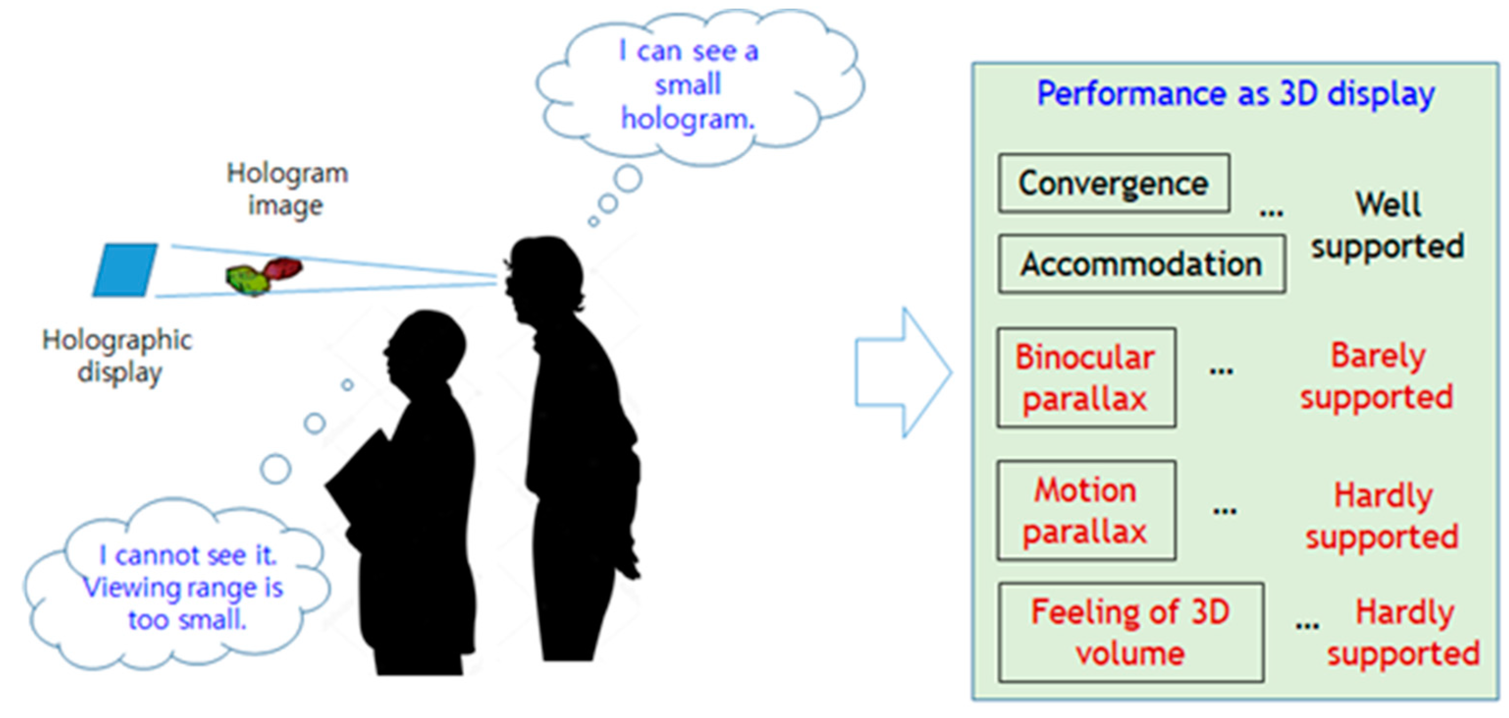
All of these holographic display systems are of the ‘front-viewing’ type implementations. Holographic 3-dimensional images are seen in front or behind the display depending on the content to be rendered. Since the viewing angle is small, it can hardly give any volumetric feeling or perception different from conventional multiview displays, while image size and quality is much inferior to them. So, even though the theory tells strength of the holographic display, practical implementations do not yet realize desired superiority of the technology. This situation is depicted in Figure 1. Recently, there have been several other approaches for different type of holographic displays trying to render more volumetric holographic images, either floating in the air [13] or seen from 360 degrees around [14,15]. In reference [13], only one viewer can see the image, and in reference [15], one can see only side views, while the display in reference [14] can show top side views, thus neither one is fulfilling the capability of rendering true volumetric image. On the other hand, there have also been several tabletop display systems demonstrated their quite impressive capability of volumetric 3-dimensional image rendering in the free air, which easily enables some manipulations and interactions with the content [16,17,18]. These displays shows the usefulness of the tabletop displays, but crucial weakness remains regarding human factor issue, since it cannot support visual accommodation cue of the human 3D vision. This can only be achieved by holographic technology, though super-multiview or integral imaging has also been claimed to have a very similar property [19,20,21]. In summary, the tabletop holographic display system with rendering capability of more realistic volumetric 3D images is yet to be developed, which is far better than typical ‘front-viewing’ type ones.
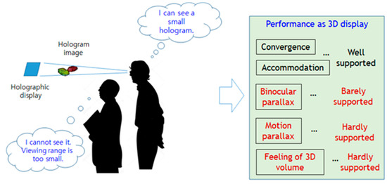
Figure 1.
Current status of state-of-the-art holographic displays.
3. Design Concept and Methodologies
In the following are our design goals of tabletop holographic display implementation. What we had in mind from the start is that the system should be designed to evolve eventually to a commercially viable system.
- (1)
- The size of the hologram image should be reasonably big enough so that viewers can perceive the 3-dimentional volume and some details of the image.
- (2)
- The hologram image should be seen by multiple viewers at the same time, and freely from different positions and perspectives so that each viewer can easily perceive the whole shape of rendered objects and all viewers can share the whole scene information in order to discuss about, or collaboratively manipulate, on it.
- (3)
- The image should be rendered in such a way that binocular disparity and motion parallax is perceived to a satisfactory level. In other words, the image should deliver the perception of real objects being there, showing all around perspective views of the object with full parallax.
- (4)
- No physical apparatus of the display should occupy the image space, so that the hologram image is shown in free air, enabling manipulation or interaction with the image as if we do with real objects.
- (5)
- High quality color hologram image with dynamic content, i.e., the hologram video should be presented.
Also note that vergence-accommodation conflict-free property should basically be supported since the system is real holographic display. Performance specification of the display system to be realized is drawn from these requirements, which is summarized in Table 2.

Table 2.
Performance specification of the system.
A drawing of the system design goal and schematic diagram of the main system specifications are shown in Figure 2.

Figure 2.
(a) Conceptual drawing of the design goal. (b) Schematics of system specifications.
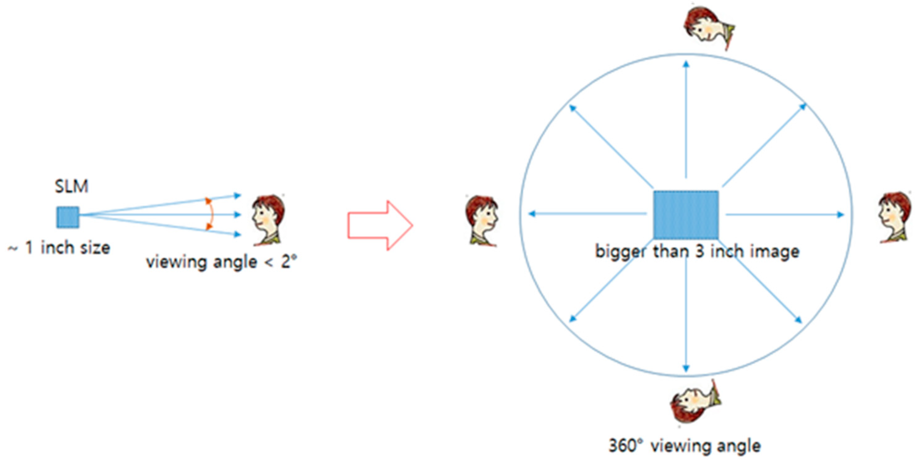
It is quite challenging to realize these requirements into working display system with currently available commercial SLM devices, since most of them have a physical size of modulation area less than one inch and diffraction angle less than 2 degrees. Figure 3 shows this issue in a schematic diagram. We need to enlarge virtual modulation device to bigger than three inches and also enlarge the field of view to cover 360 degrees.
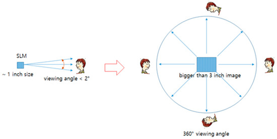
Figure 3.
Basic challenge of the system design.
Viewing angle of 360 degrees can only be achieved by either temporally scanning or spatially tiling a small viewing angle of native SLM device. The former method needs temporal multiplexing with fast SLM and the latter one needs spatial tiling with multiple SLMs. The very first thing to do in the system design is to decide on the basic architecture with the selection of appropriate SLM device. We decided to adopt the temporal multiplexing scheme and fast SLM, based on the comparison of expected system complexity and maximum data throughput of SLMs. Usually the performance of an SLM device is denoted by SBP, which is cited most often to compare different SLM devices. SBP simply represents the total pixel numbers of an SLM device, while total data throughput of a device comes from the combination of pixel count and frame rate. Total data throughput actually determines whole system performance in terms of hologram image rendering, thus is more appropriate to judge the performance of an SLM. This quantity is named extended SBP(eSBP), which is defined in Equation (1):
eSBP = SBP ∗ frame rate (or refresh rate) = (pixel resolution) ∗ (frame rate)
Some of typical SLM devices are compared in terms of SBP and eSBP in Table 3. From the table, we see that although the SBP of DMD is smaller than LCD or LCoS, the eSBP value is much larger.

Table 3.
Comparison of SBP and eSBP for different SLM devices.
We utilize the large eSBP value of a DMD device to spatially distribute fast refreshing hologram images by temporal multiplexing, thus achieving very wide viewing angle. The following details the basic methods that we applied to the display system design for the required specifications.
- (1)
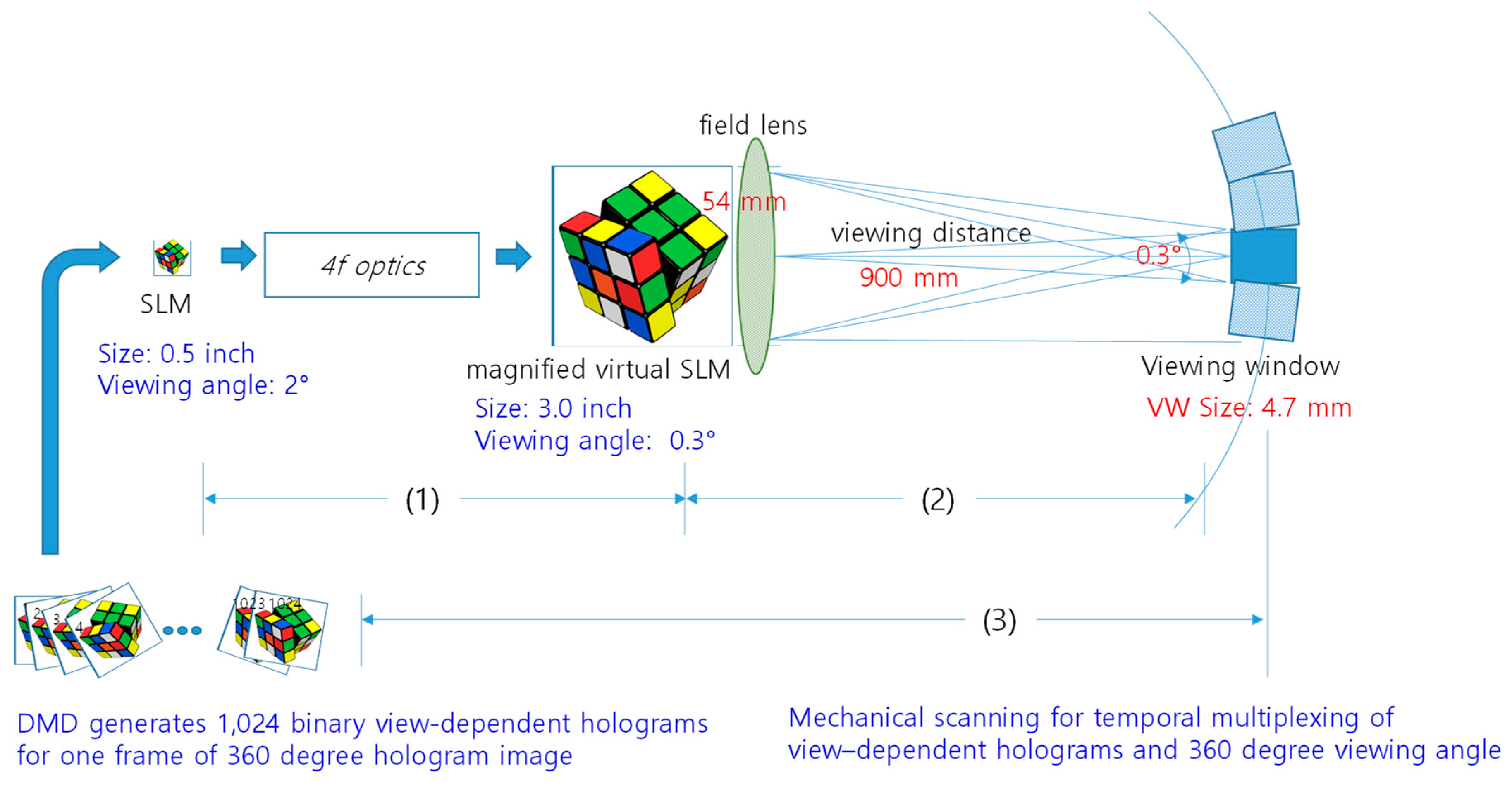
- Image size is first enlarged by simple optical magnification using 4-f optics, which results in enlarged virtual SLM (from 1.27 cm to 7.62 cm). The price of this image enlargement is reduced diffraction angle of the virtual enlarged SLM (from 2° to 0.3°).
- (2)
- We make a viewing window at viewing distance of 900 mm by adding a field lens in the position of virtual SLM plane, forming the size of 4.7 mm × 4.7 mm rectangular viewing window.
- (3)
- Seamless horizontal viewing zone is made by circularly tiling the viewing windows of the appropriate number of viewpoint-dependent hologram images. In our system, the viewing zone has a circumferential length of ~4000 mm, which can be covered by tiling more than 851 viewing windows. In actual implementation, 1024 viewing windows are tiled with some overlap between adjacent ones. This is achieved by temporal multiplexing with mechanical scanning optics.
Steps (1)–(3) are shown in Figure 4.
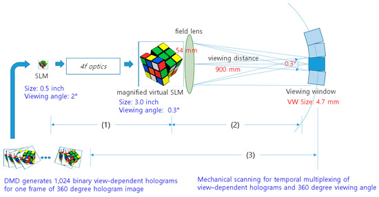
Figure 4.
Schematic diagram of the design (1), (2), and (3) denotes the corresponding step in the text.
- (4)
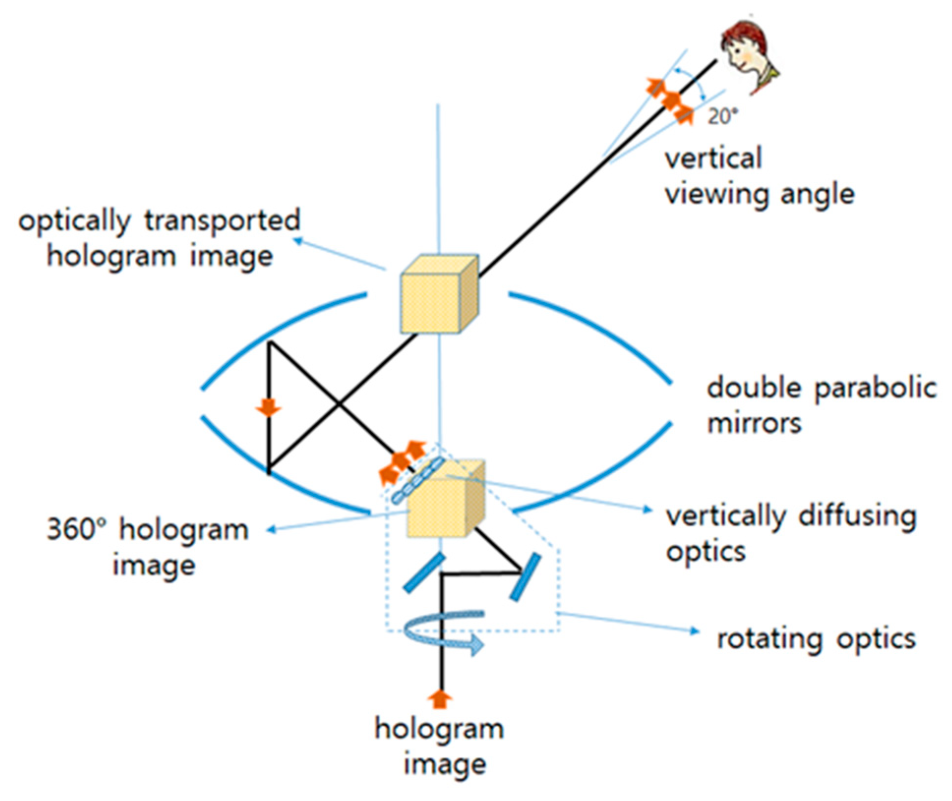
- The viewpoint-dependent hologram images are designed to be seen at the center of the tabletop display, so that coalition of them makes a volumetric 3-dimentional image floating in the air. This is achieved by two stages of optics. In the first stage, the light path of the hologram image is guided by a combination of flat mirrors into 45-degree slanted direction and in a way to overlap at the axial area of the system. In the second stage, these virtual SLM planes are transported to the top center area of the tabletop display (final hologram image plane in the air above the tabletop of the display) by image transportation function of double parabolic mirrors from one focal area to another. This is shown in Figure 5.
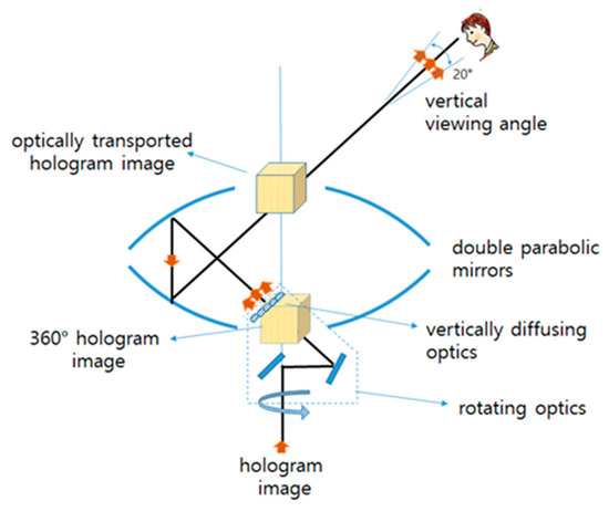 Figure 5. 360-degree volumetric image floating on tabletop display.
Based on this principal design method, we have successfully implemented the first monocolor version of tabletop holographic display systems, which has been reported in the previous publication [22]. In the first prototype system, four DMDs are spatially tiled to make a 2 × 2 multivision style SLM module for enhanced resolution (from 768 × 768 to 1,536 × 1536) and size (1.27 to 2.54 cm). This still small size of SLM is enlarged by a cascade of two 4-f optics, with the magnification factor of 1.67 and 1.65 each, overall resulting in 2.76 times of magnification effect. For rejection of DC and high order noise, a single-sideband (SSB) filter is inserted in the Fourier plane of the first 4-f optics. It is monocolor system with a green (wavelength of 632 nm) laser as a light source. For the detail specifications of optical components used in the display system, please refer to [1]. In the second and later implementations of our system, the following are added as well as the enhanced functions.
- (1)
- The SLM module for color hologram generation is designed using three DMDs for each monocolor (R, G, and B) hologram, combining optics consisting of two prisms (one is trichroic and the other is TIR (total internal reflection) type), and three laser light sources with collimated beam output. In this way we preserve the image resolution of the monocolor display in color holographic display. Refer to [22] for some implementation details.
- (2)
- We have thus far a vertically narrow (4.7 mm) viewing stripe around and over the display. A vertical viewing angle of 20° is also required in order to permit the viewers’ free position or posture (sitting on a chair, standing, or somewhere in between, as shown in Figure 2b) to view the hologram image, and this is achieved by adding vertical diffuser optics (a lenticular sheet, which is schematically shown in Figure 5) at the virtual SLM plane. Since diffusing optics degrades the spatial focusing capability of hologram somewhat, there is a tradeoff in this regard.
- (3)
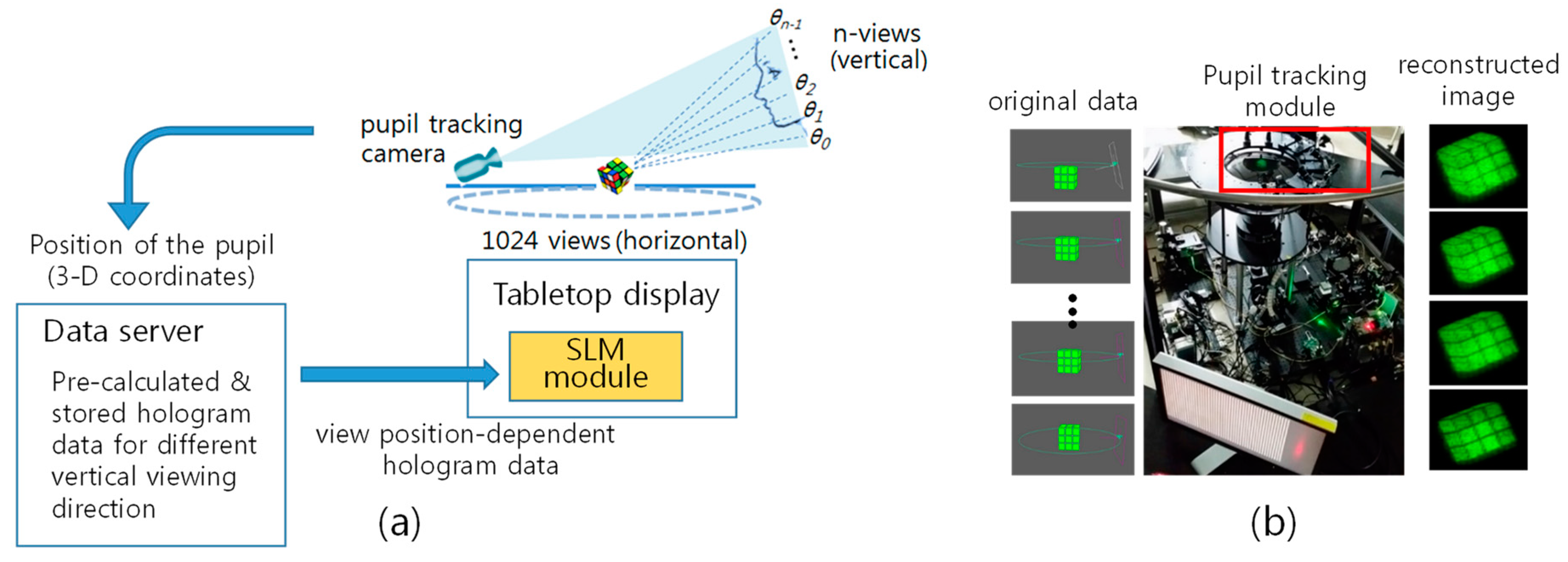
- Vertical parallax is added inside this 20° of vertical viewing range (between 35° and 55° from the tabletop). For this, precise and fast pupil tracking of viewers with a dynamic update of the hologram images is implemented for a limited number of viewers. Pupil tracking module consists of multiple IR illuminator and cameras. Two cameras working as a stereo camera covers a viewer in 90° range, and four camera sets are used for 360° coverage, while supporting four viewers simultaneously. Figure 6 shows the working concept of the module and experimental setup for 180° coverage with reconstructed image at four different vertical positions. Currently, update of pupil position is limited to 10 times per second, which is not sufficient for smooth update of hologram images following viewer’s motion.
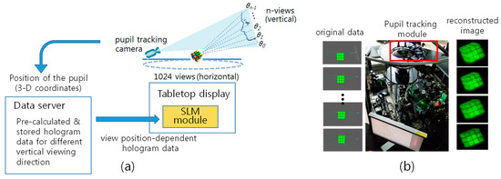 Figure 6. Vertical parallax support by using pupil tracking and dynamic hologram update. (a) Conceptual model and (b) 180° pupil tracking module and hologram images seen at four different vertical viewing position.
 - (4)
- Capture of 3D information from moving real objects and the 360-degree perspective hologram CGH is implemented, and thus the signal chain from capture-CGH to display is demonstrated.
4. Implementation and Experimental Result
The basic system we implemented is a vertically diffused horizontal parallax only (VD-HPO) hologram system. This system is the one without pupil tracking module, having a 20° vertical viewing angle and a nonsupported vertical parallax, which is similar to rainbow hologram. With pupil tracking module added, the system becomes a full parallax hologram system.
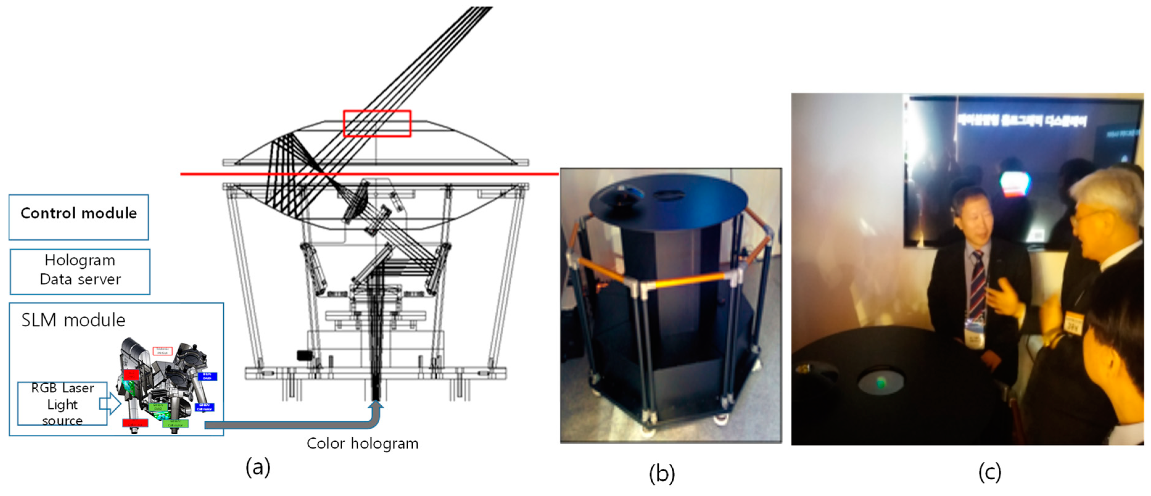
Schematic diagram of the basic display system and photo of the final system shape are shown in Figure 7. The system consists of an SLM module consisting of laser light source and three DMDs, 4-f relay optics for image magnification and noise filtering, temporal multiplexing module consisting of a scanning motor and light path redirecting optics, and volumetric image floating optics consisting of double parabolic mirrors or equivalent optics.
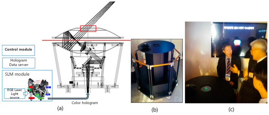
Figure 7.
(a) Schematic configuration. (b) Photo of the implemented system. (c) Demonstration.
Three-hundred-and-sixty-degree viewable volumetric color hologram image is rendered in the display by coalition of 1024 view-dependent holograms, which are generated from 3D data consisting of color and depth image for each viewpoint from a CG model or scanning real objects. Figure 8 shows the whole signal chain from 360° 3D data capture from real moving or static objects, possibly including humans, CGH computation, and real-time hologram data transmission via data server with high speed interface up to display system. There are several highly complicated signal processing tasks involved in the chain. The 360° data capture part has two alternative setups: one consists of a single depth sensing camera with a turntable for a static object and the other, for moving objects, consists of multiple synchronized depth sensing cameras arranged 120 degrees apart. Image registration and stitching, smoothing, and hole-filling algorithms are applied to get point cloud data which is optionally converted to 3D mesh model. Finally RGB and depth image data are extracted via virtual camera setting for required number of viewpoints of the tabletop display. This data is input to the CGH computation module, algorithm of which is calculating wave propagation model of the display optics, outputting hologram fringe patterns. Details of this CGH are presented in reference [23]. The hologram data is uploaded to data server and finally transmitted to the SLM module of the display in real time via high speed interface from data server to the display system.

Figure 8.
Signal processing chain of the tabletop holographic display system.
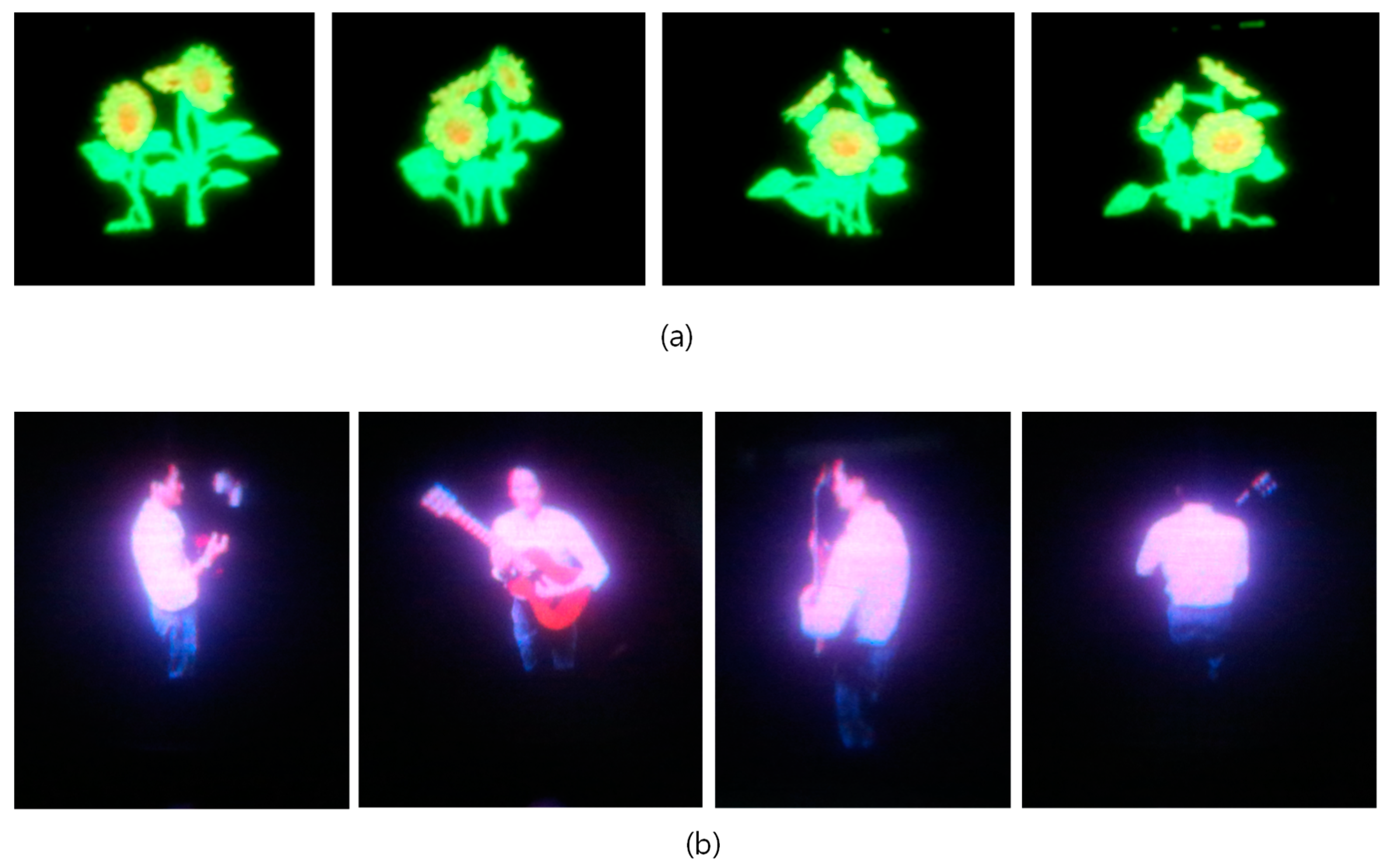
Images of optically reconstructed hologram images from the implemented display system are shown in Figure 9.
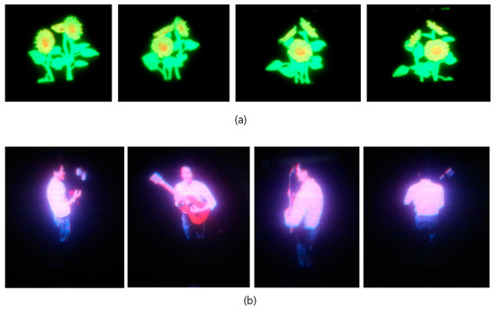
Figure 9.
Optically-reconstructed hologram image captured from different horizontal viewpoints: (a) CG model and (b) real human object.
5. Measurements and Evaluation
It is not less important to measure and evaluate the performance and image qualities of the final holographic displays than system implementation itself. A study of how to define display performance measure or image quality has been carried out by only a few researchers so far [24,25].
In order to evaluate performance of a holographic display and compare with different systems, we need to define appropriate performance metrics. Since holographic displays have different characteristics and behavior, existing performance metrics for conventional 2D displays are not sufficient. In Table 4, some essential performance metrics we defined for holographic 3D displays are listed. For the implemented display system, we measured and evaluated several important properties based on this performance metric.

Table 4.
Metrics and their definitions for holographic performance measure.
5.1. Size of the Image Volume Space
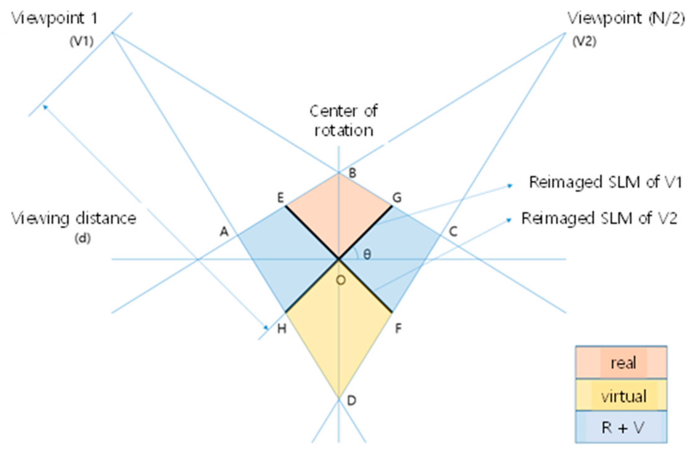
In our tabletop holographic display, a 3-dimensional image is rendered in free space and virtually occupies a volume space, as represented in Figure 10. This image space is made from intersections of adjacent viewing cones, each of which corresponds to a viewpoint and hologram pair. It can be divided into real and virtual image areas, which are seamlessly composing the whole volume space for the hologram image. If we render hologram image inside this image volume, then it is seen much like a real object supporting binocular as well as motion parallax.
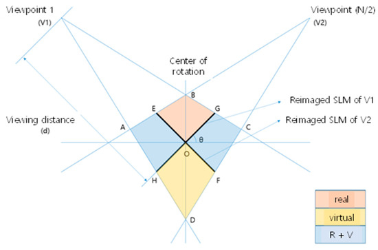
Figure 10.
Image volume space.
5.2. Hologram Image Resolution
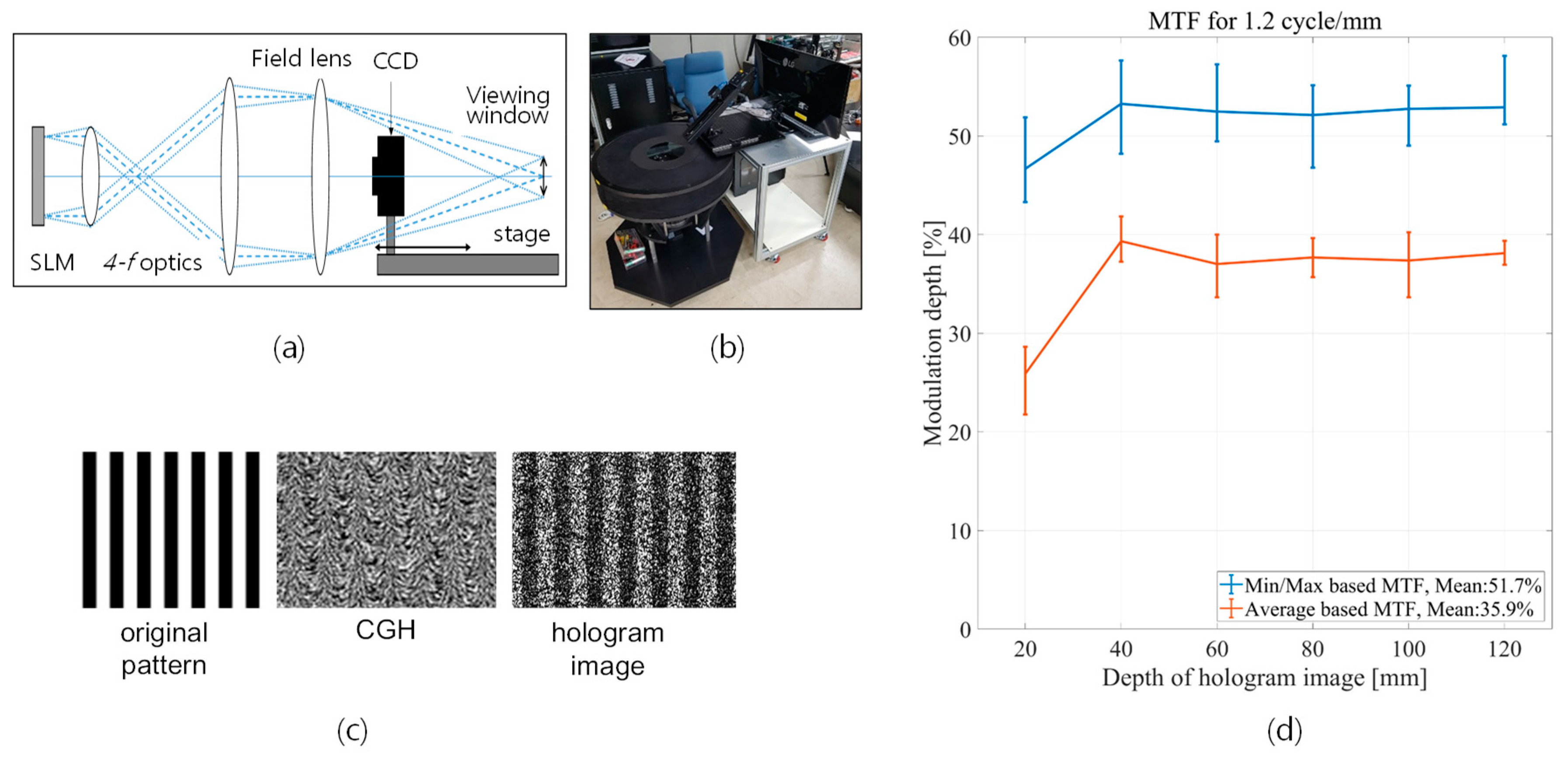
Since the hologram image is rendered in free space as a volumetric image, simple pixel resolution does not properly represent the resolution or quality of optically reconstructed hologram image. We defined a new metric for representing the image resolution, which we named 3D-MTF. The modulation transfer function (MTF) is usually used to measure the performance of an optical device like lens in terms of how well it conveys the contrast of an object to the image. MTF is modulation depth denoted as a function of frequency of the test pattern as shown in Equation (2). A 3D-MTF is defined as an extension of conventional MTF by adding depth as another parameter, which is defined as in Equation (3):
where, M is modulation depth, Imax and Imin are the maximum and minimum signal intensity of signal, respectively, Ma(b) is the modulation depth of a as a function of b, ΔD is depth resolution, and N is the number of depth layers used in the measurement. MTFk is the MTF value measured at the k-th depth plane. Defined as such, 3D-MTF is a collection of conventional MTF measured for images at different depth. We measured 3D-MTF value of the implemented display system as shown in Figure 11. For the purpose of accurate measurement, hologram image is captured directly by CCD (Sony ICX834) placed at different depth plane for a fixed viewpoint (Figure 11a). A linear stage and a green laser with a 532 nm wavelength are used in the experiment. An example black and white stripe pattern used in the measurement is shown in Figure 11c, in the order of original shape, its CGH fringe pattern, and reconstructed hologram image. For each stripe pair of the test pattern, modulation depth value is measured and average value of whole stripe pairs is plotted for each depth in Figure 11d. The ranges of measured values for whole stripe pairs at each depth are denoted by vertical bars. MTF changes with image depth, and the average value of MTF is 35.9%@1.2cycles/mm test pattern. More details of measurement and evaluation are given in Appendix A. In reference [26], a holographic stereogram is analyzed for MTF modeling, showing the effect of phase error arising from approximating the wavefront of a 3D image with a wavefront of a projected image at stereogram plane. While a holographic stereogram can be analyzed as a diffraction-limited imaging system with some aberrations, our display system relies on the diffraction to make a real or virtual image, which requires different analysis. Furthermore, binary encoding of computed fringe pattern results in distortions of frequency spectrum, which should be taken care of. This is remained for further study.
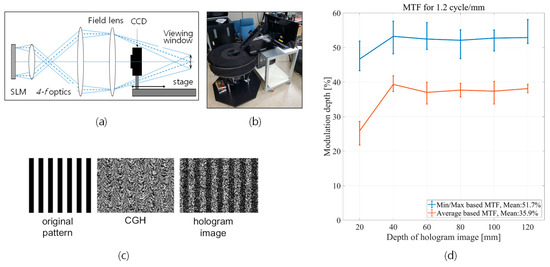
Figure 11.
3D-MTF measurement: (a) design of test method, (b) environment setup for measurement, (c) test pattern, and (d) result of the measurement.
5.3. Color Gamut and Color Reproduction Fidelity
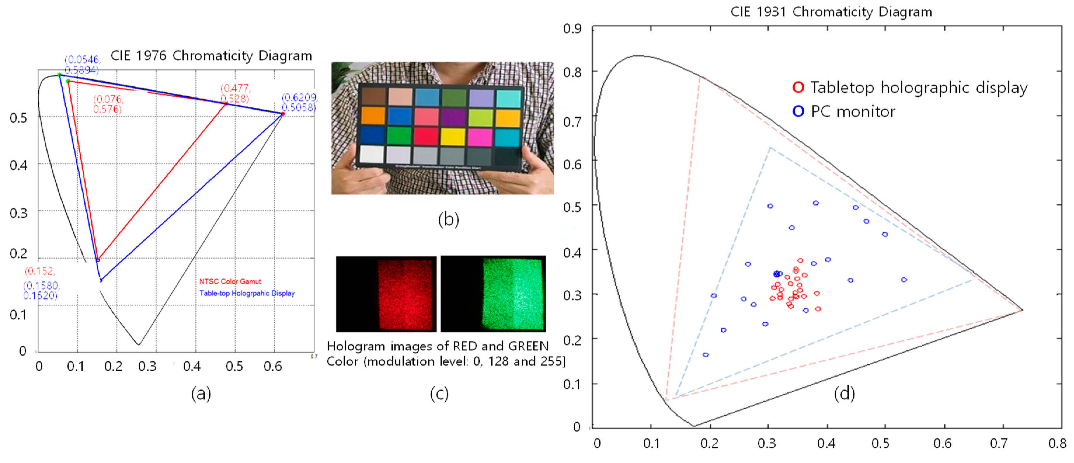
In a full color holographic display, color reproduction fidelity is not actually guaranteed even though color gamut of the display system is wider than conventional ones. Figure 11a shows the measured color gamut of our display, which is ~160% wider than CIE 1976 NTSC standard (1953). On the contrary, Figure 12d shows the measured color fidelity for the 24 colors in a standard Macbeth color chart. Blue dots represent desired values and red dots are measured ones. As shown in Figure 12c, optically reconstructed hologram image is corrupted with speckle and other noise, so that colors corresponding to two modulation levels (125 and 255) are not clearly distinguished. As a result, color separation is very bad. Quantification of this result is under study.
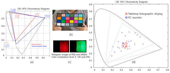
Figure 12.
Color gamut and color fidelity of implemented system, (a) color gamut, (b) 24 color Gretag-Macbeth ColorChecker, (c) hologram image, and (d) measured color fidelity.
5.4. Speckle Noise
Speckle noise in holographic displays mainly comes from the use of coherent light sources like laser, which is one of major sources of quality degradation of hologram image. Measurement and analysis of speckle noise is well-studied, and speckle contrast is the most used metric to judge the severity of the speckle [27]. There has been quite a lot of researches for speckle noise reduction methods [28,29], and most of them is based on the concept of temporal multiplexing and averaging down overall speckle contrast. We developed an angular spectrum interleaving method, which is verified being able to reduce—by 60%—the level of speckle noise of the system down to 10% [30]. We are currently working on the physical realization of this method for our display system.
5.5. Degree of Depth of Focus (DoF)
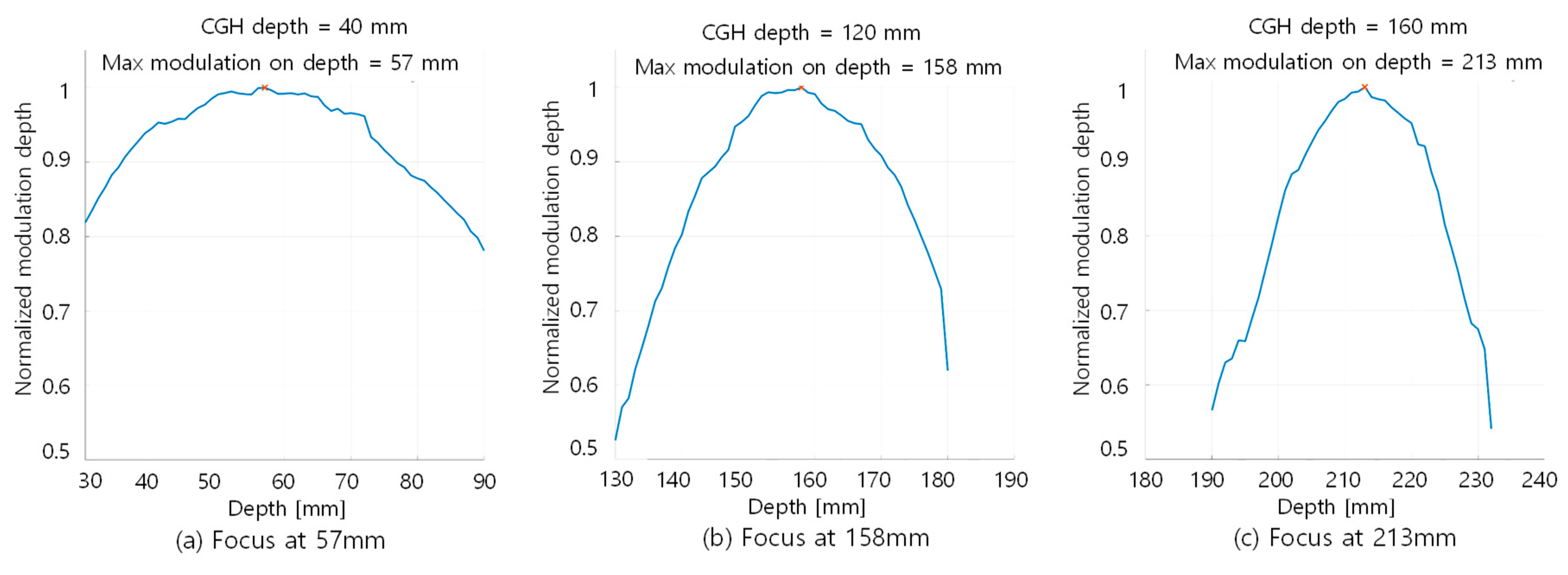
As is always mentioned, the holographic display is most distinguished from other conventional 3D displays in the sense that it has the capability of supporting accommodation of human visual system. This means that holographic display can render an image at a specified depth plane, which can be focused as real objects. In previous studies, this has been simply demonstrated by showing two or more objects rendered at different distance, one of which is focused the others become defocused and blurred when captured by a shallow DoF camera. We can evaluate this capability of a display by using a very similar method to measuring 3D-MTF. For an MTF test pattern imaged at a certain depth plane, measuring MTF around the plane in viewing direction can tell how well the image is focused to the plane and defocused elsewhere. Figure 13a–c shows modulation depth values measured for a test pattern imaged at distances of 57 mm, 158 mm, and 213 mm from the virtual SLM plane, respectively. There are discrepancies between the measured image depth and the intended depth rendered in the CGH algorithm, which are 40 mm, 120 mm, and 160 mm. This is believed to be caused from the slight difference between the dimensions of designed and actual optical signal path of the system. It represents varying depth representation capability of the display through the image rendering volume. These modulation depth curves are obtained using the exact same measurement method as is used for obtaining MTF curves. Since for a real hologram image the spherically converging wavefront is supposed to focus at the image plane, defocusing or blur in front or behind this focal plane should be symmetric. So, deviations more than measurement error from this expected symmetry may come from aberrations of the optics of the system.
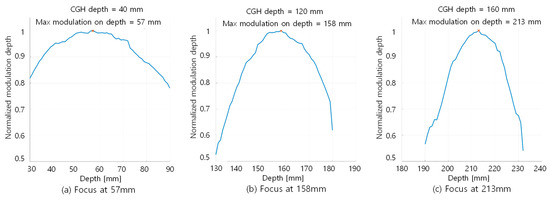
Figure 13.
Degree of DoF at different depths, measured with MTF test patterns.
6. Conclusions
As visual media become pervasive in our daily life and more visual information is used for effective communication among people, new tools for more realistic visual content representation and exchange are required. Digital holographic technology is the most wanted one in this regard, since it can perfectly reproduce the visual experience we do meet every day. Due to the rapid progress in every field of technology, commercialization of digital holographic displays and imaging systems becomes visible. Since the working principle and requirements of holographic display systems are quite different from those of conventional displays, we need to explore diverse ways to realize commercially viable systems. In this paper, we presented design concepts, implementation methods of a new type of tabletop holographic display system, and addressed the important issue of measurement and quantitative evaluation for objective comparison of different systems. Especially important is that the quality and resolution of the reconstructed hologram image is measured and analyzed in terms of 3D-MTF, color reproduction fidelity, and degree of DoF. Though we designed each optical component for minimum aberration [20], the system we developed has several elements which degrade the quality of final image, including binary amplitude encoding of the fringe and mechanical movement during image rendering time. Rigorous analysis of the system regarding this issue remains as a future work. We hope this work gives some hint for future development of commercially acceptable holographic display systems.
Author Contributions
Writing—Original Draft Preparation, J.K.; Writing—Review and Editing, Y.L., K.H., H.K., H.-E.K., J.N., J.P., J.H., and Y.K.
Funding
This work was supported by the cross ministry GigaKorea project (GK18D0100, Development of Telecommunications Terminal with Digital Holographic Table-top Display) grant funded by the Korea government (MSIT).
Acknowledgments
This work is a part of the result of collaboration of ETRI and participating universities, companies and research institutes. Participated organizations: LG display, ASTEL, Aoptics, Yunam Optics, Funzin, SiliconWorks, MVTech, KETI, KIST, Konyang University, Korea University, Inha University, Kyungpook University, Sejong University, Kwangwoon University, and Warsaw University of Technology.
Conflicts of Interest
The authors declare no conflict of interest.
Appendix A
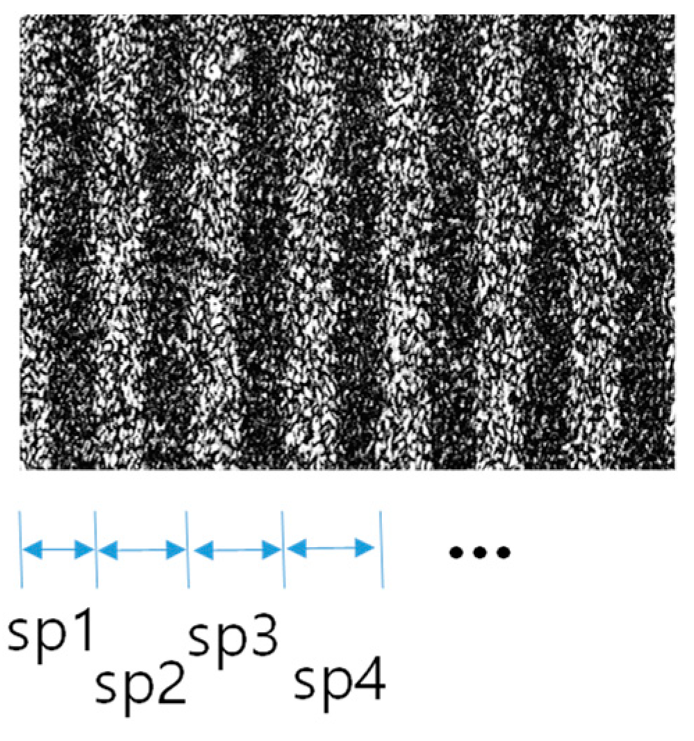
In this appendix, more details of 3D-MTF measurements and result of evaluation are presented. Figure A1 shows an optically reconstructed hologram image for a test pattern. Each stripe pair consists of a black and a white vertical bar of width 416.67 μm (1.2 cycles/mm). The CCD sensor (Sony ICX834) we used in the experiment has pixel size of 3.1 μm, so a black (or white) stripe is captured by about 134 pixels in horizontal direction. For each of horizontal pixel positions of the CCD sensor, pixel values are accumulated in vertical direction, which are the raw data we used for MTF calculation. Minmax-based MTF is calculated using maximum value (among 134 values) of white stripe and minimum value of black stripe. Average-based MTF is calculated using the average value of each black and white stripe. Depending on the depth we measure, twelve to fourteen stripe pairs were used, and the average value (yellow box in Table A1) is represented as the MTF value of corresponding depth in Figure 11d, with the range of values denoted by vertical bars in the graph. Standard deviation is also calculated and shown in the last column with heading of ‘stdev’ in Table A1. The measurement is carried out for a system without the lenticular sheet, which is used for extending vertical viewing angle. Measurements for Figure 13 are done with the same method.
Table A1.
Measured values for MTF calculations.

a.
Minmax_based MTF.
a.
Minmax_based MTF.
| depth | 20 | 40 | 60 | 80 | 100 | 120 |
| max | 0.519 | 0.576 | 0.572 | 0.551 | 0.551 | 0.581 |
| mean | 0.467 | 0.533 | 0.525 | 0.521 | 0.527 | 0.529 |
| min | 0.433 | 0.482 | 0.494 | 0.468 | 0.490 | 0.511 |

b.
| SP# | 1 | 2 | 3 | 4 | 5 | 6 | 7 | 8 | 9 | 10 | 11 | 12 | 13 | 14 | average | Stdev |
| 20 | 0.459 | 0.458 | 0.447 | 0.461 | 0.454 | 0.469 | 0.475 | 0.498 | 0.484 | 0.519 | 0.433 | 0.453 | 0.449 | 0.474 | 0.467 | 0.022 |
| 40 | 0.527 | 0.545 | 0.550 | 0.543 | 0.576 | 0.523 | 0.542 | 0.521 | 0.482 | 0.519 | 0.529 | 0.537 | 0.530 | 0.533 | 0.022 | |
| 60 | 0.518 | 0.507 | 0.532 | 0.526 | 0.529 | 0.504 | 0.572 | 0.528 | 0.494 | 0.528 | 0.531 | 0.505 | 0.561 | 0.509 | 0.525 | 0.022 |
| 80 | 0.497 | 0.551 | 0.523 | 0.533 | 0.516 | 0.536 | 0.541 | 0.546 | 0.484 | 0.518 | 0.468 | 0.542 | 0.521 | 0.026 | ||
| 100 | 0.545 | 0.536 | 0.517 | 0.547 | 0.526 | 0.551 | 0.515 | 0.499 | 0.519 | 0.529 | 0.536 | 0.544 | 0.490 | 0.527 | 0.019 | |
| 120 | 0.520 | 0.521 | 0.524 | 0.541 | 0.517 | 0.524 | 0.527 | 0.523 | 0.581 | 0.511 | 0.532 | 0.526 | 0.529 | 0.018 |

c.
Average_based MTF.
c.
Average_based MTF.
| depth | 20 | 40 | 60 | 80 | 100 | 120 |
| max | 0.286 | 0.418 | 0.400 | 0.396 | 0.402 | 0.393 |
| mean | 0.259 | 0.393 | 0.370 | 0.377 | 0.374 | 0.381 |
| min | 0.217 | 0.372 | 0.336 | 0.357 | 0.336 | 0.369 |

d.
| SP# | 1 | 2 | 3 | 4 | 5 | 6 | 7 | 8 | 9 | 10 | 11 | 12 | 13 | 14 | average | Stdev |
| 20 | 0.286 | 0.260 | 0.276 | 0.247 | 0.284 | 0.271 | 0.243 | 0.262 | 0.279 | 0.252 | 0.251 | 0.260 | 0.217 | 0.231 | 0.259 | 0.020 |
| 40 | 0.405 | 0.418 | 0.400 | 0.413 | 0.400 | 0.393 | 0.394 | 0.380 | 0.378 | 0.382 | 0.372 | 0.383 | 0.391 | 0.393 | 0.014 | |
| 60 | 0.375 | 0.369 | 0.400 | 0.363 | 0.383 | 0.371 | 0.388 | 0.370 | 0.359 | 0.373 | 0.366 | 0.336 | 0.365 | 0.360 | 0.370 | 0.015 |
| 80 | 0.359 | 0.396 | 0.376 | 0.387 | 0.381 | 0.382 | 0.386 | 0.382 | 0.365 | 0.363 | 0.357 | 0.385 | 0.377 | 0.013 | ||
| 100 | 0.388 | 0.370 | 0.378 | 0.402 | 0.380 | 0.368 | 0.392 | 0.361 | 0.383 | 0.368 | 0.363 | 0.368 | 0.336 | 0.374 | 0.017 | |
| 120 | 0.369 | 0.370 | 0.382 | 0.384 | 0.387 | 0.393 | 0.383 | 0.382 | 0.387 | 0.370 | 0.383 | 0.382 | 0.381 | 0.008 |
SP#: stripe pair number.
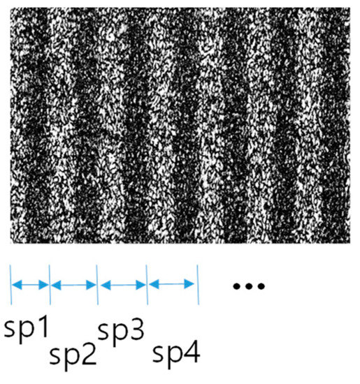
Figure A1.
Reconstructed hologram image at 80 mm depth (brightness level is enhanced for clear presentation).
Figure A1.
Reconstructed hologram image at 80 mm depth (brightness level is enhanced for clear presentation).
References
- Lim, Y.; Hong, K.; Kim, H.; Kim, H.-E.; Chang, E.-Y.; Lee, S.; Kim, T.; Nam, J.; Choo, H.-G.; Kim, J.; et al. 360-degree tabletop electronic holographic display. Opt. Express 2016, 24, 24999–25009. [Google Scholar] [CrossRef] [PubMed]
- St-Hilaire, P.; Benton, S.A.; Lucente, M.E.; Jepsen, M.L.; Kollin, J.; Yoshikawa, H.; Underkoffler, J.S. Electronic display system for computational holography. In Proceedings of the SPIE, Los Angeles, CA, USA, 18–19 January 1990; pp. 174–182. [Google Scholar]
- Smalley, D.E.; Smithwick, Q.Y.J.; Bove, V.M.; Barabas, J.; Jolly, S. Anisotropic leaky-mode modulator for holographic video displays. Nature 2013, 498, 313–317. [Google Scholar] [CrossRef] [PubMed]
- Häussler, R.; Reichelt, S.; Leister, N.; Zschau, E.; Missbach, R.; Schwerdtner, A. Large real-time holographic displays: From prototypes to a consumer product. IS&T/SPIE Electron. Imaging 2009, 7237, 72370. [Google Scholar]
- Hahn, J.; Kim, H.; Lim, Y.; Park, G.; Lee, B. Wide viewing angle dynamic holographic stereogram with a curved array of spatial light modulators. Opt. Express 2008, 16, 12372–12386. [Google Scholar] [CrossRef] [PubMed]
- Senoh, T.; Mishina, T.; Yamamoto, K.; Oi, R.; Kurita, T. Viewing-Zone-Angle-Expanded Color Electronic Holography System Using Ultra-High-Definition Liquid Crystal Displays with Undesirable Light Elimination. J. Display Technol. 2011, 7, 382–390. [Google Scholar] [CrossRef]
- Oi, R.; Sasaki, H.; Wakunami, K.; Ichihashi, Y.; Senoh, T.; Yamamoto, K. Large size three-dimensional video by electronic holography using multiple spatial light modulators. Sci. Rep. 2014, 4, 6177. [Google Scholar]
- Takaki, Y.; Okada, N. Hologram generation by horizontal scanning of a high-speed spatial light modulator. Appl. Opt. 2009, 48, 3255–3260. [Google Scholar] [CrossRef] [PubMed]
- Takaki, Y.; Matsumoto, Y.; Nakajima, T. Color image generation for screen-scanning holographic display. Opt. Express 2015, 23, 26986–26998. [Google Scholar] [CrossRef] [PubMed]
- Blanche, P.-A.; Bablumian, A.; Voorakaranam, R.; Christenson, C.; Lin, W.; Gu, T.; Flores, D.; Wang, P.; Hsieh, W.-Y.; Kathaperumal, M.; et al. Holographic three-dimensional telepresence using large-area photorefractive polymer. Nature 2010, 468, 80–83. [Google Scholar] [CrossRef] [PubMed]
- Park, M.; Chae, B.G.; Kim, H.; Hahn, J.; Moon, K.; Moon, K.; Kim, J. Digital Holographic Display System with Large Screen Based on Viewing Window Movement for 3D Video Service. ETRI J. 2014, 36, 232–241. [Google Scholar] [CrossRef]
- Blinder, D.; Ahar, A.; Bettens, S.; Birnbaum, T.; Symeonidou, A.; Ottevaere, H.; Schretter, C.; Schelkens, P. Signal processing challenges for digital holographic video display systems. Signal Process. Image Commun. 2019, 70, 114–130. [Google Scholar] [CrossRef]
- Kawashima, T.; Kakue, T.; Nishitsuji, T.; Suzuki, K.; Shimobaba, T.; Ito, T. Aerial projection of three-dimensional motion pictures by electro-holography and parabolic mirrors. Sci. Rep. 2015, 5, 11750. [Google Scholar]
- Inoue, T.; Takaki, Y. Table screen 360-degree holographic display using circular viewing-zone scanning. Opt. Express 2015, 23, 6533–6542. [Google Scholar] [CrossRef] [PubMed]
- Sando, Y.; Barada, D.; Yatagai, T. Holographic 3D display observable for multiple simultaneous viewers from all horizontal directions by using a time division method. Opt. Lett. 2014, 39, 5555. [Google Scholar] [CrossRef] [PubMed]
- Jones, A.; McDowall, I.; Yamada, H.; Bolas, M.; Debevec, P. Rendering for an Interactive 360° Light Field Display. ACM Trans. Graph. 2007, 26, 40. [Google Scholar]
- Butler, A.; Hilliges, O.; Izadi, S.; Hodges, S.; Molyneaux, D.; Kim, D.; Kong, D. Vermeer: Direct Interaction with a 360° Viewable 3D Display. In Proceedings of the ACM Symposium on User Interface Software and Technology, Santa Barbara, CA, USA, 16–19 October 2011. [Google Scholar]
- Yoshida, S. fVisiOn: 360-degree viewable glasses-free tabletop 3D display composed of conical screen and modular project arrays. Opt. Express 2016, 24, 13194–13203. [Google Scholar] [CrossRef] [PubMed]
- Takaki, Y. High-Density Directional Display for Generating Natural Three-Dimensional Images. Proc. IEEE 2006, 94, 654–663. [Google Scholar] [CrossRef]
- Takaki, Y.; Nago, N. Multi-projection of lenticular displays to construct a 256-view super multi-view display. Opt. Express 2010, 18, 8824–8835. [Google Scholar] [CrossRef]
- Hua, H.; Javidi, B. A 3D integral imaging optical see-through head-mounted display. Opt. Express 2014, 22, 13484. [Google Scholar] [CrossRef]
- Kim, J.; Hong, K.; Lim, Y.; Kim, J.-H.; Park, M. Design options for 360 degree viewable table-top digital color holographic displays. In Proceedings of the SPIE Commercial + Scientific Sensing and Imaging, Orlando, FL, USA, 15–19 April 2018. [Google Scholar]
- Chang, E.-Y.; Choi, J.; Lee, S.; Kwon, S.; Yoo, J.; Choo, H.-G.; Kim, J. 360-degree Color Hologram Generation for Real 3-D Object. Dig. Holography Three-Dimens. Imaging 2018, 57, A91–A100. [Google Scholar] [CrossRef]
- Seo, W.; Song, H.; An, J.; Seo, J.; Sung, G.; Kim, Y.-T.; Choi, C.-S.; Kim, S.; Kim, H.; Kim, Y.; et al. Image Quality Assessment for Holographic Display. In Proceedings of the IS&T International Symposium on Electronic Imaging 2017, Burlingame, CA, USA, 29–31 January 2017. [Google Scholar]
- Yoshikawa, H.; Yamaguchi, T. Image Quality Evaluation of a Computer-Generated Hologram. In Proceedings of the Digital Holography & 3-D Imaging Meeting, Orlando, FL, USA, 25–28 June 2018. [Google Scholar]
- Hilaire, P.S. Modulation transfer function and optimum sampling of holographic stereograms. Appl. Opt. 1994, 33, 768–774. [Google Scholar] [CrossRef]
- Ong, D.C.; Solanki, S.; Liang, X.; Xu, X. Analysis of laser speckle severity, granularity, and anisotropy using the power spectral density in polar-coordinate representation. Opt. Eng. 2012, 51, 054301. [Google Scholar] [CrossRef]
- Takaki, Y.; Yokouchi, M. Speckle-free and grayscale hologram reconstruction using time-multiplexing technique. Opt. Express 2011, 19, 7567–7579. [Google Scholar] [CrossRef] [PubMed]
- Makowski, M. Minimized speckle noise in lens-less holographic projection by pixel separation. Opt. Express 2013, 21, 29205–29216. [Google Scholar] [CrossRef] [PubMed]
- Lim, Y.; Park, J.; Hahn, J.; Kim, H.; Hong, K.; Kim, J. Reducing speckle artifacts in digital holography by the use of programmable filtration. ETRI J. 2019. [Google Scholar] [CrossRef]
© 2019 by the authors. Licensee MDPI, Basel, Switzerland. This article is an open access article distributed under the terms and conditions of the Creative Commons Attribution (CC BY) license (http://creativecommons.org/licenses/by/4.0/).

