Article

Novel Liquid Transfer Active Balancing System for Hollow Rotors of High-Speed Rotating Machinery

1
Key Laboratory of Engine Health Monitoring-Control and Networking (Ministry of Education), Beijing University of Chemical Technology, Beijing 100029, China
2
Beijing Key Laboratory of Health Monitoring and Self-Recovery for High-End Mechanical Equipment, Beijing University of Chemical Technology, Beijing 100029, China
3
China Special Equipment Inspection and Research Institute, Beijing 100029, China
*
Authors to whom correspondence should be addressed.
Appl. Sci. 2019, 9(5), 833; https://doi.org/10.3390/app9050833
Submission received: 4 January 2019 / Revised: 10 February 2019 / Accepted: 20 February 2019 / Published: 26 February 2019

Abstract

:

Featured Application

The proposed liquid transfer active balancing system can effectively decrease the unbalance vibration of high-speed rotating machinery in operation.

Abstract

With the development of high-speed rotating machinery, the unbalance vibration feature of each rotor system has a greater influence on the work efficiency, bearing life, operational time, etc. Therefore, an active balancing system is necessary to automatically reduce the unbalance vibration in the process of rotor operation. This study introduced a novel liquid transfer active balancing system for the hollow rotors, and compensation mass was performed by balance liquid transmission between two pairs of contra-positioned chambers. The performance of this new balance actuator was analyzed, including balancing velocity, balancing accuracy, and the effect on rotor dynamics. A monitoring and control program was constructed to control the balance actuator. Two extraction methods of synchronic vibration were introduced and quantitatively compared through simulation. A control program was developed and the control accuracy was within 1 ms. Furthermore, the effectiveness of the new balancing system was verified through active balance experiments and the maximum speed was 15,600 rpm. The results indicate that the balancing system could effectively decrease the unbalance vibration of the rotor system within 10 s, and the amount of decrease was more than 80%.

1. Introduction

Mass imbalance is a common fault of rotating machinery. To achieve higher production efficiency, the working speed of these machines has been increased. Higher rotational speed demands higher dynamic balance accuracy, and this demand has led scholars to study better dynamic balancing methods.
In general, there are two categories of research on dynamic balance technology: offline balance technology and online automatic balance technology. Owing to the difference in balancing principles, offline balance research can take several directions, such as the influence coefficient method [1,2,3], modal analysis method [4], field balancing [5,6], and the virtual dynamic balance method [7,8]. These methods can reduce the unbalance vibration of the machinery in the field; however, using this procedure, the rotating machinery needs to stop working and even stop several times, which results in time and economic losses. Online automatic balance technology can automatically decrease the unbalance vibration using a balance actuator that is rotating with the rotor when the vibration amplitude exceeds the limit value in the rotor operation process. This avoids the start and stop process in the offline balance.
Based on the structural features of the balance actuator, there are several types of online automatic balance technology, such as ball-type [9,10], hydraulic type [11], pendulum type [12], magnetic-bearing type [13], electromechanical type [14], electromagnetic-ring type [15,16], and liquid-type [17,18,19,20]. The first three can redistribute mass to automatically compensate for the unbalance based on the self-alignment phenomenon occurring in the planar rotor, and these are called passive balancing devices. The latter four need a control unit to send commands during the balancing operation and are called active balancing devices, which have better balancing accuracy than the passive devices. The magnetic-bearing type actuator reduces the unbalance vibration by means of synchronous electromagnetic force which cannot be removed after balancing, thus its scope of application is limited by the large power consumption [13]. The electromechanical type and the electromagnetic-ring type actuators use the eccentric mass blocks to compensate for the initial unbalance of the rotors [14,15,16], and, to change the mass distribution of the mass blocks, several movable components are needed in the structure design, such as motors, transmission chains, and ball bearings, which are easily deformed and locked under centrifugal force in high-speed applications. The liquid-type actuator compensates for the initial unbalance through the liquid mass distribution, and its commercial product is called liquid-injection type or Hydrokompenser [17]. Given that the construction of the liquid-injection type is simpler and it does not have movable components in the rotating part, it is more suitable than the other three active balancing actuators. Unfortunately, the liquid injecting procedure can cause environmental pollution, restricts the application of the products, and results in the balance capacity decreasing with the balancing number. Therefore, many studies have been done to solve these disadvantages. For example, the liquid injection and dripping type actuator was proposed to solve the problem of losing balancing ability, by possessing a continuous balancing ability [18]; and the liquid transfer type actuator for the grinding machine was proposed to solve the liquid injection problem during balancing by redistributing the liquid in the balancing disc through compressed air [19,20]. However, these studies were conducted in low or medium speed situations, i.e., below 5500 rpm; therefore, the issue of how to solve the disadvantages in high-speed applications over 10,000 rpm has not been studied. Furthermore, at present, these liquid actuators are installed on the shaft or on the end, and there is no solution to the requirement for mounting in the hollow rotor.
A monitoring and control program is also needed to control this balance actuator, which always monitors and extracts the unbalance vibration status of the rotor system during the working operation. When the unbalance vibration amplitude exceeds the set value, it calculates the correction mass and performs the balancing. Many studies have been conducted to improve the accuracy of the feature extraction [21,22,23], but for the active balancing system, the accuracy and speed of the feature extraction should be considered simultaneously. Otherwise, the control unit cannot send the control command in time.
To solve the above problems, this study proposed a novel liquid-transfer active balancing system, which can be installed in the hollow rotors to reduce the unbalance vibration by mass redistribution in four contra-positioned chambers. The performance of the new balance actuator was analyzed. Two extraction methods of synchronic vibration were introduced and quantitatively compared through simulation. An active balancing experiment was conducted and the maximum speed was 15,600 rpm. The results indicated that the balancing system could effectively decrease the unbalance vibration of the rotor system within 10 s.

2. Operating Principle of the Active Balancing System

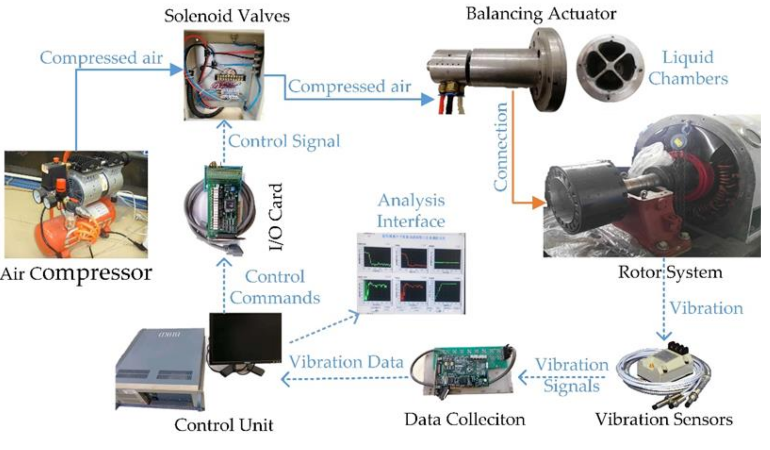
2.1. Balancing System

The liquid transfer balancing system introduced in this paper is driven by compressed air. The system comprises a control subsystem, a balance actuator built in the hollow rotor system, and an air subsystem. A flowchart of the active balancing system is presented in Figure 1. The operating principle can be indicated as follows: several vibration sensors and a data collection system are used to measure the vibration of the hollow rotor system. From these vibration data, the unbalance vibration amplitude and phase are continuously obtained by the control unit, and, when the vibration amplitude exceeds its set value, the control unit will start the balancing operation. Based on the detected unbalance vibration, the control unit determines the compensation mass and transmits control commands to the solenoid valves through the input/output (I/O) card. Compressed air from the air compressor is then led to the balance actuator that is pre-built in the hollow rotor system. Through the gas channels in the actuator, compressed air flows into the required chamber, and then the liquid in the relevant chamber is impressed into the contrary chamber. The mass distribution of the balance disc is altered through the liquid transmission between two contra-positioned chambers, and a compensation mass is generated to decrease the unbalance vibration of the rotor system. The balance actuator stops working and the solenoid valves are closed until the unbalance vibration amplitude increases to its set value again.

2.2. Balance Actuator

The balance actuator, which determines the function of the total system, is the core of the balancing system, and it comprises a liquid disc and an air distributor, as shown in Figure 2. The liquid disc has two pairs of orthogonal liquid chambers, and each pair has two contra-positioned chambers that are pre-filled with balance liquid before installation. Each chamber has a corresponding gas channel along which the compressed air can enter the chamber and transfer the balance liquid, and each pair of contra-positioned chambers is connected by a liquid channel. To process these four gas channels and two liquid channels, the cover plates are divided into four pieces and are welded together with the disc using brazing welding. A strength test is also needed to check the welding quality.
Compressed air is delivered from the standing air tubes to the liquid disc through an air distributor, which comprises a casing, a sleeve, and two bearings. There are four holes on the outer wall of the casing that are used to connect with four air pipelines. To prevent air from escaping, a middle sleeve made from polytetrafluoroethylene is needed to transfer the compressed air. More specifically, the air distributor and the balance disc are connected by a rotary shaft integrated with the cover plates of the liquid disc, and there are also four gas inlet holes on the outer wall of the shaft to form the gas channels. The air distributor and the rotary shaft are separated by a small gap. Accordingly, to guarantee the long-cycle operation of the balance actuator, two bearings are adopted between these two components.

2.3. Balancing Principle

The oscillatory differential equation of a rotor system can be expressed by:
m x ¨ + c x ˙ + k x = F 0 cos ( ω t + φ )
where the mass, the damping, the stiffness, and the rotating speed of the rotor are expressed by m, C, k, and ω, respectively; and F0 is the unbalance force of the rotor system.
By solving the differential Equation, the vibration amplitude of the rotor caused by imbalance is given by the following Equation:
x = F 0 ( k m ω 2 ) 2 + c 2 ω 2
Before balancing the vibration of the rotor system with liquid actuator, a balancing disc rotating synchronously with the rotor should be installed on the rotor in advance. The balancing disc contains four liquid chambers to store the balance liquid. Through adjusting the liquid mass distribution in the balancing disc, a correction mass is formed, and then the active balancing system can on-line balance the rotor system.
When the balancing disc rotates synchronously with the rotor, the balance liquid in the liquid chamber distributes annularly along the outer wall of the chamber under centrifugal force, as shown in Figure 3. Assuming V′ is the liquid volume in one chamber, through an integration calculation, the centrifugal force formed by the liquid in the chamber is derived as follows:
F = 2 3 ρ B ω 2 [ R 3 ( R 2 2 V B θ ) 3 2 ] sin θ 2
where ω is the angular speed of the rotor, ρ is the density of balance liquid, R is the outer radius of the liquid chamber, B is the depth of the liquid chamber, and θ is the central angle of the chamber.
Therefore, the resultant force Fx in the x-axis direction can be derived by:
F x = F A F C = 2 3 ρ B ω 2 [ ( R 2 2 V C B θ ) 3 2   ( R 2 2 V A B θ ) 3 2 ] sin θ 2
For the liquid transfer type actuator, the same amount of balance liquid will be pre-filled into the four liquid chambers before balancing and the amount can by expressed by V′. In the working process, each pair of liquid chambers works at the same time. If the liquid in one chamber increases, then the liquid in the other chamber will inevitably decrease, thus the increase and decrease are equal. Assuming the volume of the transfer liquid is Vx, Equation (4) can be rewritten to
F x = F A F C = 2 3 ρ B ω 2 [ ( R 2 2 ( V V x ) B θ ) 3 2   ( R 2 2 ( V + V x ) B θ ) 3 2 ] sin θ 2
The resultant force Fy in the vertical direction can be obtained in the same way, so the resultant force in the two directions can be orthogonally synthesized to obtain the composite force F1 formed by the actuator, that is F 1 = F x 2 + F y 2 . The direction of the composite force is opposite to that of the unbalanced force.
Therefore, the oscillatory differential equation of a rotor system can be rewritten as follows
( m + m a ) x ¨ + c x ˙ + k x = ( F 0 F 1 ) cos ( ω t + φ )
where ma is the mass of the balancing disc itself. In the design process, to minimize the effect of the additional mass on the dynamic characteristics of the rotor system, the mass of the balancing disc should be far less than the mass of the rotor.
When the control unit of the balancing system drives the liquid transfer in the balancing disc, the compensation force F1 produced by the balancing disc will be approximately equal to the initial unbalance force F0, so the excitation force of the rotor system is minimized and the unbalance vibration amplitude of the system can be reduced to the set value.

3. Performance Analysis of Balance Actuator

3.1. Balancing Velocity

For the liquid-transfer balance actuator, one connecting tube was used to connect two contra-positioned chambers, as shown in Figure 4. Here, we take the contra-positioned chambers A and C, as an example. Point 1 and Point 3 denote the two ends of the connecting tube. Between these two points, the Bernoulli equation is expressed by
g z 1 + p 1 ρ + u 1 2 2 ω 2 2 r 1 2 k u 2 2 = g z 3 + p 3 ρ + u 3 2 2 ω 2 2 r 3 2
where u refers to the flow velocity of the balance liquid, and k stands for the drag coefficient along the transfer path. The radius r1 is identical to that of r3, and the velocity u1 starts from zero. Assuming gravity is neglected, Equation (7) is simplified to
p 1 p 3 ρ = k + 1 2 u 2
The gas pressure in Chamber A is zero, and pressure p3 is equal to the pressure formed by the balance liquid in Chamber A, that is:
p 3 = p 0 + p V A = ρ ω 2 B θ V A
The gas pressure in Chamber C is identical to the pressure of the compressed air flowing into the chamber, and pressure p1 is expressed by
p 1 = p 0 + p V C = p 0 + ρ ω 2 B θ V C
During the liquid transmission procedure, the overall volume of the balance liquid V′AC in the two chambers is constant, so the relationship between them can be derived by
V A = V A C V C
Therefore, the flow velocity or balancing velocity in the connecting tube is obtained by
u = 2 ρ ( k + 1 ) [ p 0 + ρ ω 2 B θ ( 2 V C V A C ) ]
Assuming xc is the variable expressing the relationship between the liquid volume VC and the true volume of Chamber C, Equation (12) is deformed to
u = 2 ρ ( k + 1 ) [ p 0 + ρ ω 2 B θ V ( 2 x c 0.5 ) ]
If the basic parameters of the liquid chamber and the gas pressure are known, the balancing velocity depends on the drag coefficient along the transfer path k, which can be expressed by
k = λ l d + ζ
where λ is the friction coefficient, ζ is the local drag coefficient, and d and l are the equivalent diameter and length of the connecting tube, respectively.
From the experimental results, we can see that the flow condition in the connecting tube is laminar flow, so the friction coefficient can be expressed by λ = 64/Re, and the Reynolds number Re can be obtained by
Re = ρ u d μ = 10 3 u d ν
where ν is the kinematic viscosity of the balance liquid.
Finally, the flow velocity or balancing velocity in the connecting tube is presented by
u = 31.25 d 2 ρ ν l [ p 0 + ρ ω 2 B θ V ( 2 x C 0.5 ) ]
For the balance actuator used in the following experiment, its basic parameters are given in Table 1. Silicone oil was used as the balance liquid, and its kinematic viscosity ν can be chosen from a wide range (10–100, 000 cSt). Figure 5 shows the relationship between the balancing velocity u and xc, with a gas pressure of 0.6 MPa and an operating speed of 15,000 rpm.
The results indicate two conclusions: (1) Under constant gas pressure and working speed, the balancing velocity u was related to the volume and viscosity of the balance liquid. With the decreased volume of the liquid and increased liquid viscosity, the transfer velocity of the balance liquid would decrease. (2) The absolute error of the balancing velocity could be effectively reduced by increased liquid viscosity. For example, when the liquid viscosity increased from 100 cSt to 500 cSt, the absolute error of the balancing velocity could be reduced from 1 m/s to 0.1 m/s, which could be used to change the performance of the balance actuator.

3.2. Balancing Accuracy

During the balancing procedure, the balance actuator could progressively decrease the unbalance vibration of the detected rotor system through the mass distribution. The minimum amount of mass change could be used to express the balancing accuracy of the balance actuator, and smaller amounts indicated a higher balancing accuracy. The minimum amount of mass change can be expressed by
M min = ρ u max s t
where umax is the maximum balancing velocity, s is the section of the connecting tube, and t is the minimum action time. The minimum action time t was mainly determined by the delay time of the controller, the response time of the solenoid valves, and the delay time in the process of gas transmission. The experimental results show that the minimum action time was 0.05 s.
From the linearity analysis of the balance capacity [24], the change of balance capacity and the transfer mass were linearly related, and the linear coefficient dU/dm for the actuator in this paper was about 25 (g.mm)/g. Therefore, the minimum amount of balance capacity can be obtained by
Δ U min = d U d m M min
The results in Figure 5 show that, when the kinematic viscosity of the balance liquid was 100 cSt and 300 cSt, the maximum balancing velocity umax was 3.0 m/s and 1.0 m/s, respectively. Substituting these parameters into Equation (18), the minimum amount of balance capacity ΔUmin was about 7 g.mm and 2.4 g.mm.
According to GB/T 9239.1-2006, the permissible residual imbalance Uper is represented as
U p e r = 1000 m e p e r 9549.3 m G n
where G is the required balance level, m is the effective mass of the rotor system, and n is the working speed. For the actuator used in this experiment, the total mass of the rotor system was about 16.5 kg, and its permissible residual imbalance with different balance levels is shown in Table 2.
According to the criterion ΔUmin < 2Uper, the final balancing accuracy of the experimental setup was G0.4, with the kinematic viscosity of balance liquid higher than 100 cSt.

3.3. Effect on Rotor Dynamics

When a balance actuator is designed, the mass should be far less than the mass of the rotor to minimize the effect of the additional mass on the dynamic characteristics of the rotor system. The actuator used in the following experiment was made from an aluminum alloy, and a finite element analysis was conducted to evaluate its effect on the rotor dynamics, as shown in Figure 6. From the results, we could conclude that the critical speed of the initial rotor system was 20,020 rpm; after installing the actuator, the value was reduced to 19,216 rpm, representing a 4% decrease. The working speed of the rotor system was below 16,000 rpm, so the design was reasonable and did not affect the normal operation of the rotor system.

4. Feature Extraction and Control Methods

4.1. Monitoring and Control Program

For the active balancing system, a control unit was necessary to control the balance actuator, and the control loop is shown in Figure 7. A monitoring and control program was constructed to monitor the vibration status of the rotor system during normal operation. When the unbalance vibration amplitude exceeds its set value, the program makes a calculation of the compensation mass by adopting of the known influence coefficient, and then commands are sent to the solenoid valves. The relevant solenoid valves are opened and compressed air flows into the target chamber via the related air pipeline, and then the balance liquid is transferred. Figure 7 shows a block diagram of the control loop.

4.2. Feature Extraction

The active balancing system operates to reduce the unbalance vibration. If some errors occur in the extraction of the unbalance vibration, then several parameters of the balancing system will go into effect, such as balancing accuracy, balancing speed, and action time. Even when the error is large, the balancing operation will increase the vibration of the rotor and cause a misalignment. Therefore, it is particularly important to accurately extract the phase and amplitude of the unbalance vibration of the rotor system.

4.2.1. Tracking-Filter Method

The tracking filter method is also called the correlation filtering method. Its working principle is mainly based on the orthogonality of the triangular function [24]. The initial vibration signal can be expressed by
x ( t ) = A 0 cos ( 2 π f 0 t φ 0 ) + i = 1 N A i cos ( 2 π f i t φ i )
where f0 is the working frequency of the rotor system.
One sinusoidal signal y1 and one cosine signal y2 are provided, and their frequencies are equal to f0, that is,
y 1 ( t ) = sin ( 2 π f 0 t ) ,   y 2 ( t ) = cos ( 2 π f 0 t )
Multiplying Equation (20) by Equation (21) gives:
x ( t ) y 1 ( t ) = 1 2 A 0 sin φ 0 + 1 2 A 0 sin ( 4 π f 0 t φ 0 ) + 1 2 i = 1 N A i sin [ 2 π ( f 0 + f i ) t φ i ] + 1 2 i = 1 N A i sin [ 2 π ( f 0 + f i ) t + φ i ]
x ( t ) y 2 ( t ) = 1 2 A 0 cos φ 0 + 1 2 A 0 cos ( 4 π f 0 t φ 0 ) + 1 2 i = 1 N A i cos [ 2 π ( f 0 + f i ) t φ i ]   + 1 2 i = 1 N A i cos [ 2 π ( f 0 + f i ) t + φ i ]
DC components in Equations (22) and (23) are extracted with the application of a low-pass filter, and the extraction results can be obtained by:
V x = 1 2 A 0 sin φ 0 , V y = 1 2 A 0 cos φ 0
Multiplying Equation (24) by Equation (21) again, the unbalance vibration of the rotor system is expressed by:
x 0 ( t ) = 2 × ( 1 2 A 0 sin φ 0 sin ( 2 π f 0 t ) + 1 2 A 0 cos φ 0 cos ( 2 π f 0 t ) ) = A 0 ( sin ( 2 π f 0 t ) sin φ 0 + cos ( 2 π f 0 t ) cos φ 0 ) =   A 0 cos ( 2 π f 0 t φ 0 )
where A0 and φ 0 are the amplitude and phase of unbalance vibration, respectively.

4.2.2. Cross-Power Spectrum Method

The method is based on the principle of eliminating noise by a cross-correlation operation. The initial signal and a standard sinusoidal signal are cross-correlated, and the frequency of the sinusoidal signal is identical to the working frequency of the rotor system. The similar frequency component of the initial signal that is equal to the working frequency is strengthened, and the components of noise and other frequencies are effectively suppressed. Then, the amplitude as well as the phase of the same frequency signal are solved by using the cross-power spectral density function [24].
The initial vibration signal and the standard sinusoidal signal are the same as Equations (20) and (21). The cross-correlation between these two signals is calculated by their convolution sum, so the cross-correlation function can be obtained by:
C x y ( τ ) = E [ x ( t ) μ x ] E [ ( y ( t τ ) μ y ) * ]
where μx and μy are the mean values of these two signals.
The cross-power spectral density function refers to the Fourier transform of the cross-correlation function, and it is expressed by:
P x y ( w ) = C x y ( τ ) e i w τ d τ = π A 0 2 e j φ 0 δ ( 2 π f 0 w ) + π A 0 2 e j φ 0 δ ( 2 π f 0 + w )
where δ is the Dirac function. When ω is equal to 2πf0, Equation (27) can be simplified to:
P x y ( w 0 ) = π A 0 2 e j φ 0
Therefore, by computing the modulus and phase angle of the complex number, the amplitude A0 and phase φ 0 of the unbalance vibration can be obtained.

4.2.3. Simulation

According to the principle of these two methods, two simulation programs were developed based on the LabVIEW platform.
The amplitude of the initial signal and phase were set to 4 μm and 140°, respectively. To quantitatively compare the extraction errors between these two methods, a noise signal was introduced to simulate the actual working conditions by adjusting its standard deviation. The comparison results are shown in Table 3.
Two conclusions could be drawn from the results: (1) the extraction error increased gradually with the enhancement of the noise signal; and (2) the extraction error of the tracking-filter method was less than that of the cross-power method, which was limited by the sample rate. Therefore, when it is hard to increase the sample rate as determined by the data collection equipment, it is better to use the tracking-filter method to extract the unbalance vibration.
Additionally, the phase from these two methods is the phase of initial vibration, but in the actual balancing process, the required parameter is the peak phase of the vibration. After using the two methods to extract the vibration phase θ, the value needs to be converted to the peak phase δ, and the relationship between the two phases is shown in Figure 8. The transformation function can be expressed by
δ = { 90 0 ( 0 0 θ < 90 0 ) 450 0 θ ( 90 0 θ < 360 0 )

4.3. Control Program

In the active balancing system, the I/O card named PCI-6172 was used to output the control commands of the control unit and to connect with solenoid valves. The normal state of these channels in the I/O card is open and the control loop is disconnected, so that none of the solenoid valves work. When the control unit outputs a control command, the channel corresponding to the solenoid valve is closed, the control loop is turned on, and the corresponding solenoid valve starts to work. To ensure that the channels opened correctly, the corresponding channels of each solenoid valve were coded binary, that is, 20, 21, 22, and 23. If two solenoid valves needed to be opened at the same time, the output code of the control unit was the sum of the corresponding channel codes. Since only adjacent chambers had the possibility of opening at the same time and the contra-positioned chambers were forbidden to work simultaneously, there were eight codes to control the four solenoid valves: 1, 2, 4, 8, 3, 6, 9, and 12. The first four codes were used to open one solenoid valve, and the last four codes were used to open the two simultaneously. Based on the LabVIEW platform, the control program was developed, and a schematic diagram is shown in Figure 9. After debugging the program, two conclusions could be drawn: (1) when these codes were sent to the I/O card, the corresponding solenoid valve could open correctly; and (2) when the work time of the solenoid valves increased from 100 ms to 2000 ms by 100 ms steps, the control accuracy of each step was within 1 ms. Therefore, the control program could satisfy the need for control accuracy of the balancing system.

5. Balancing Experiments

The effectiveness of the new active balancing system was verified through several active balance experiments, and the experimental devices were constructed as shown in Figure 10.

5.1. Introduction of the Experimental Devices

The high-speed experimental rig in Figure 10 is composed of three parts: the main body, the display cabinet, and the air source control cabinet.
The main body was composed of a liquid balance actuator, an electric spindle, a sensor bracket, a protection cover, and an experimental base. A high-speed spindle was used to install the balance actuator, and the maximum operating speed was 16,000 r/min. A counterweight wheel with the geometrical dimensions 180 mm, 75 mm, and 20 mm was used to simulate the unbalance. The vibration of the rotor system was detected with the use of several sensors. The outer diameter of the balance disc was 48 mm, and the depth was 70 mm. Silicone oil was chosen as the balance liquid, and the maximum balance capacity was approximately to 320 g.mm. Specifications of these experimental devices are indicated in Table 4.
The air source control cabinet consisted of a filter pressure reducing valve, a valve group with four solenoid valves and a display header. The following functions could be realized: (1) air from the air source could be adjusted to the target pressure; (2) when the balance actuator was ordered to work, the solenoid valve group was designed to control the delivery of the compressed air; and (3) the pressure of compressed air was measured and displayed. The required pressure of compressed air was less than 0.6 MPa, so an air compressor with 0.8 MPa was connected to the air source control cabinet. The display cabinet was mainly composed of a vibration display screen, four indicator lights, and an emergency stop button. The vibration display screen was used to show the vibration data of the experimental platform, and the four indicator lights corresponding to the four liquid chambers of the balance disc were used to display the target in the process of gas injection.

5.2. Balancing Experiments and Results

The limiting value of the unbalance vibration was set to 0.4 μm during the balance experiments. When the vibration amplitude exceeded the set value, control commands were sent out and the balance actuator started working. After the vibration amplitude was lower than 0.4 μm again, the actuator stopped working.
Active balancing experiments were conducted at three speeds: 9000 rpm, 12,000 rpm, and 15,600 rpm.
The overall signal and corresponding frequency spectrogram at 9000 rpm are shown in Figure 11. Figure 11a shows that the balance time was within 10 s. Fast Fourier Transformation (FFT) analysis was done, and the frequency spectrogram before and after balancing (Figure 11b) showed that the synchronic vibration was a majority in the overall vibration before balancing, and the balance actuator could efficiently reduce the synchronic vibration to below the limiting value. Through active balancing, the synchronous vibration component decreased from 4.8 μm to 0.32 μm, being a 93% decrease. The mass redistribution had little effect on the other harmonic signals, except for the synchronic signal, so the decreased overall vibration was related to the share of the synchronic vibration.
At the next two speeds, the change in synchronic vibration during the balancing process was as shown in Figure 12. At 12,000 rpm, the initial unbalance vibration was 2.5 μm and it decreased to 0.23 μm through active balancing. The amount decreased by 90.8% and the balance time was no more than 10 s. At 15,600 rpm, the initial unbalance vibration was 1.4 μm and decreased to 0.2 μm through active balancing. The amount decreased by 85.7% and the balance time was also within 10 s.
The experimental results indicate that the novel active balancing system could effectively decrease the unbalance vibration at three speeds. The amount decreased by more than 80% and the balance time was no more than 10 s.

6. Conclusions

A novel liquid-transfer balancing system was developed in this study to decrease the unbalance vibration for the hollow rotors of high-speed rotating machinery. The performance of the new balance actuator was analyzed, including balancing velocity, balancing accuracy, and the effect on rotor dynamics. Under constant gas pressure and working speed, the balancing velocity was related to the volume and viscosity of the balance liquid, and the absolute error of balancing velocity could be effectively reduced by increased liquid viscosity. For the experimental setup, the final balancing accuracy of the balancing system was G0.4, with a less than 4% effect on the rotor system. Two extraction methods of synchronic vibration were introduced and quantitatively compared through simulation. One control program based on digital I/O card was developed and the control accuracy was within 1 ms. In addition, the effectiveness of the proposed balancing system was verified through several balancing experiments at three speeds: 9000 rpm, 12,000 rpm and 15,600 rpm. At these speeds, the new balancing system effectively decreased the unbalance vibration of the rotor system within 10 s, and the amount of the decrease was more than 80%.

7. Patents

According to the results of the work in this manuscript, the authors applied for a national invention patent (CN201610516188.4) from the Chinese Patent Office, and the patent was authorized in September 2018.

Author Contributions

Conceptualization, X.P. and H.W.; Data curation, X.P. and Z.X.; Formal analysis, J.L.; Methodology, X.P. and H.W.; Project administration, Z.J.; Software, Z.X.; Supervision, J.G.; Writing—original draft, X.P. and Z.X.; and Writing—review and editing, J.G. and Z.J.

Funding

This work was supported by the National Natural Science Foundation of China (Grant No. 51875031), the Youth Backbone Personal Project of Beijing (Grant No. 2017000020124G018) and the Fundamental Research Funds for Central Universities (Grant Nos. ZY1618 and JD1813).

Conflicts of Interest

The authors declare no conflict of interest.

Abbreviations

List of Symbols
x(t)initial vibration signalBdepth of liquid chamber
f0working frequency of the rotorllength of connecting tube
ω0angular speed of the rotordequivalent diameter of connecting tube
A0amplitude of unbalance vibrationρdensity of balance liquid
φ0phase of unbalance vibrationνkinematic viscosity of balance liquid
Cxycross-correlation functionVvolume of liquid chamber
Pxycross power spectral functionMminminimum amount of mass change
ubalancing velocitydU/dmlinear coefficient of mass change
p0pressure of compressed airΔUminminimum amount of balance capacity
kdrag coefficient in connecting tubeUperpermissible residual imbalance

References

  1. Zhang, S.; Wang, Y.; Zhang, Z. Online Dynamic Balance Technology for High Speed Spindle Based on Gain Parameter Adaption and Scheduling Control. Appl. Sci. 2018, 8, 917. [Google Scholar] [CrossRef]
  2. Levecque, N.; Mahfoud, J.; Violette, D.; Ferraris, G.; Dufour, R. Vibration reduction of a single cylinder reciprocating compressor based on multi-stage balancing. Mech. Mach. Theory 2011, 46, 1–9. [Google Scholar] [CrossRef]
  3. Kang, Y.; Lin, T.W.; Chang, Y.J. Optimal balancing of flexible rotors by minimizing the condition number of influence coefficients. Mech. Mach. Theory 2008, 43, 891–908. [Google Scholar] [CrossRef]
  4. Deepthikumar, M.B.; Sekhar, A.S.; Srikanthan, M.R. Modal balancing of flexible rotors with bow and distributed unbalance. J. Sound Vib. 2013, 24, 6216–6233. [Google Scholar] [CrossRef]
  5. Fang, J.C.; Wang, Y.G.; Han, B.C.; Zheng, S.Q. Field Balancing of Magnetically Levitated Rotors without Trial Weights. Sensors 2013, 13, 16000–16022. [Google Scholar] [CrossRef]
  6. Xu, X.B.; Chen, S. Field Balancing and Harmonic Vibration Suppression in Rigid AMB-Rotor Systems with Rotor Imbalances and Sensor Runout. Sensors 2015, 15, 21876–21897. [Google Scholar] [CrossRef] [PubMed]
  7. Li, X.; Zheng, L.; Liu, Z. Balancing of flexible rotors without trial weights based on finite element modal analysis. J. Vib. Control 2013, 19, 461–470. [Google Scholar] [CrossRef]
  8. Bin, G.F.; Li, X.J.; Shen, Y.P.; Wang, W.M. Development of whole-machine high speed balance approach for turbomachinery shaft system with N+ 1 supports. Measurement 2018, 122, 368–379. [Google Scholar] [CrossRef]
  9. Rodrigues, D.J.; Champneys, A.R.; Friswell, M.I. Experimental investigation of a single-plane automatic balancing mechanism for a rigid rotor. J. Sound Vib. 2011, 330, 385–403. [Google Scholar] [CrossRef]
  10. Ishida, Y.; Matsuura, T.; Zhang, X.L. Efficiency Improvement of an Automatic Ball Balancer. ASME J. Vib. Acoust. 2012, 134, 021012. [Google Scholar] [CrossRef]
  11. Cho, J.; Jeong, H.; Kong, K. Analysis of Dynamic Model of a Top Loading Laundry Machine with a Hydraulic Balancer. Int. J. Precis. Eng. Manuf. 2014, 15, 1615–1623. [Google Scholar] [CrossRef]
  12. Mayr, J.; Spanlang, F.; Gattringer, H. Mechatronic Design of a Self-Balancing Three-Dimensional Inertia Wheel Pendulum. Mechatronics 2015, 30, 1–10. [Google Scholar] [CrossRef]
  13. Xu, X.B.; Chen, S.; Zhang, Y. Automatic balancing of AMB systems using plural notch filter and adptive synchronous compensation. J. Sound Vib. 2016, 374, 29–42. [Google Scholar] [CrossRef]
  14. Hredzak, B.; Guo, G.X. New Electromechanical Balancing Device for Active Imbalance Compensation. J. Sound Vib. 2006, 294, 737–751. [Google Scholar] [CrossRef]
  15. Dyer, S.W.; Ni, J.; Shi, J.J. Robust optimal influence-coefficient control of multiple-plane active rotor balancing systems. ASME J. Dyn. Syst. Meas. Control 2002, 124, 41–46. [Google Scholar] [CrossRef]
  16. Fan, H.; Jing, M.; Wang, R.; Liu, H.; Zhi, J. New electromagnetic ring balancer for active imbalance compensation of rotating machinery. J. Sound Vib. 2014, 333, 3837–3858. [Google Scholar] [CrossRef]
  17. Schmitt Company. SBS Automatic Balancing System. Available online: http://www.schmitteurope.com/Balancers/SBS-automatic.html (accessed on 20 June 2018).
  18. Zhang, X.N.; Liu, X.; Zhao, H. New Active Online Balancing Method for Grinding Wheel Using Liquid Injection and Free Dripping. ASME J. Vib. Acoust. 2018, 140, 031001. [Google Scholar] [CrossRef]
  19. Pan, X.; Wu, H.Q.; Gao, J.J.; Wang, W.M. New Liquid Transfer Active Balancing System Using Compressed Air for Grinding Machine. ASME J. Vib. Acoust. 2015, 137, 011002. [Google Scholar] [CrossRef]
  20. Pan, X.; Wu, H.Q.; Gao, J.J. Rotating Machinery Targeting Self-recovery Regulation System for Imbalance Vibration Fault with Liquid-transfer Active Balancing Device. Chin. J. Mech. Eng. 2015, 51, 146–152. [Google Scholar] [CrossRef]
  21. Jiang, Z.N.; Hu, M.H.; Feng, K.; He, Y. Weak Fault Feature Extraction Scheme for Intershaft Bearings Based on Linear Prediction and Order Tracking in the Rotation Speed Difference Domain. Appl. Sci. 2017, 7, 937. [Google Scholar] [CrossRef]
  22. Hao, Y.S.; Song, L.Y.; Ke, Y.L.; Wang, H.Q.; Chen, P. Diagnosis of Compound Fault Using Sparsity Promoted-Based Sparse Component Analysis. Sensors 2017, 17, 1307. [Google Scholar] [CrossRef] [PubMed]
  23. Qin, Y.; Mao, Y.; Tang, B. Multicomponent decomposition by wavelet modulus maxima and synchronous detection. Mech. Syst. Signal Process. 2017, 91, 57–80. [Google Scholar] [CrossRef]
  24. Pan, X. Research on Priciple and Methods of Pneumatic Liquid Type and Electromagnetic Ring Type Auto-Balancing Systems for High-End Machine Tools. Ph.D. Thesis, Beijing University of Chemical Technology, Beijing, China, 2015. [Google Scholar]
Figure 1. Flowchart of the balancing system.
Applsci 09 00833 g001
Figure 2. Structure of the balance actuator.
Applsci 09 00833 g002
Figure 3. Balancing principle of the actuator.
Applsci 09 00833 g003
Figure 4. Flow procedure of the balance liquid.
Applsci 09 00833 g004
Figure 5. Balancing velocity of the balance actuator.
Applsci 09 00833 g005
Figure 6. Rotor dynamics analysis of the rotor system: (a) initial rotor system mode; (b) rotor system model with actuator; (c) analysis result of initial rotor system; and (d) analysis result of final rotor system.
Applsci 09 00833 g006
Figure 7. Block diagram of the control loop.
Applsci 09 00833 g007
Figure 8. Relationship between the initial phase and peak phase.
Applsci 09 00833 g008
Figure 9. Diagram of the control program.
Applsci 09 00833 g009
Figure 10. Test rig of the active balancing experiment. (a) overall experimental devices; (b) front view of the balance actuator; (c) vertical view of the balance actuator; and (d) control cabinet of the balancing system.
Applsci 09 00833 g010
Figure 11. Balancing results at 9000 rpm: (a) overall vibration amplitude; and (b) FFT analysis.
Applsci 09 00833 g011
Figure 12. Balancing results at: (a) 12,000 rpm; and (b) 15,600 rpm.
Applsci 09 00833 g012
Table 1. Parameters of balance actuator.
ItemsValuesItemsValues
Density of balance liquid950 kg/m3Central angle of each liquid chamber90°
Volume of each liquid chamber16 mLLength of connecting tube116 mm
Depth of each liquid chamber70 mmEquivalent diameter of connecting tube1.5 mm
Table 2. Permissible residual unbalance of the rotor system.
Working SpeedRequired Balance Level
G0.4G1.0G2.5G6.3
n(r/min)Permissible residual imbalance Uper(g.mm)
15,0004.20 10.50 26.26 66.18
Table 3. Measurement error analysis of the vibration signal.
Standard Deviation (μm)Phase Error (°)Amplitude Error (μm)
Tracking-FilterCross-PowerTracking-FilterCross-Power
0.20.270.340.0260.029
0.50.731.020.0440.044
1.01.482.030.1100.146
Table 4. Specifications of the experimental devices.
ItemMakerModel
Data acquisition cardNIPCI-6280
Digital I/O cardADVANTECHPCI-6172
Spindle motorZYS170MD18Z16
Control unitBHKDIndustrial controlling computer
Displacement sensorBently3300 XL11 mm
Speed sensorOmronE2E-X2ME1
Electromagnetic valveSMCTwo-position solenoid valve
Air sourceEluanAir compressor

