Article

Experimental Investigations on the Progressive Failure Characteristics of a Sandwiched Coal-Rock System Under Uniaxial Compression

1
College of Mining Technology, Taiyuan University of Technology, Taiyuan 030024, China
2
Research Center of Green Mining Engineering Technology in Shanxi Province, Taiyuan 030024, China
3
Priority Research Centre for Geotechnical Science & Engineering, The University of Newcastle, Callaghan, NSW 2308, Australia
*
Author to whom correspondence should be addressed.
Appl. Sci. 2019, 9(6), 1195; https://doi.org/10.3390/app9061195
Submission received: 26 February 2019 / Revised: 17 March 2019 / Accepted: 18 March 2019 / Published: 21 March 2019
(This article belongs to the Special Issue Application of Acoustic Emission (AE) on Rock Samples)

Abstract

:
Overlapped residual coal pillars, together with the surrounding rock strata, play a combined bearing role in ultra-close multiple seam mining. Global stability of the whole bearing system is significant for the mining design, construction, and operation. Laboratory uniaxial compressive experiments for different kinds of sandwiched coal-rock specimens are carried out to investigate the progressive failure characteristics and mechanisms. Results show that: (1) The mechanical behavior of the sandwiched coal-rock specimen is mainly divided into four stages during the failure process. The response of the electrical resistivity and the evolution of acoustic emission (AE) energy are in good agreement with the mechanical behaviors at different stages, which are a reflection of the global failure characteristics of sandwiched specimens. (2) The distribution of AE events and the development of local strain can provide further insight into the local failure characteristics of coal elements or rock elements in sandwiched specimens. AE events are more likely to be generated in coal elements, which can propagate across coal-rock interfaces and induce damage to rock elements in a certain area. Similarly, the unbalanced deformation characteristics of coal elements and rock elements are apparently revealed in the progressive failure process. (3) Progressive failure of a sandwiched coal-rock specimen is closely associated with the interactions between the coal elements and rock elements. Initial failure usually appears in the coal elements. At this process, the recovery of elastic deformation and the output of strain energy are observed in the rock elements, which can accelerate the rupture of coal elements. In turn, the dynamic fracture energy generated in the rupture process of coal elements can propagate into rock elements and induce damage to rock elements a certain area. (4) The experimental results are helpful for maintaining the long-term stability of a sandwiched coal-rock system in ultra-close multiple seam mining.

Graphical Abstract

1. Introduction

Abandoned coal mines are widely distributed in China [1]. Several residual coal pillars are arranged and left permanently in abandoned coal mines to support the weight of overburdened strata [2]. Dynamic failure of residual coal pillars in abandoned coal mines is usually powerful, destructive, and dangerous [3]. The long-term stability of residual coal pillars in abandoned coal mines urgently needs to be investigated.
Experiments have been performed to study the mechanical behaviors and failure characteristics of pure coal specimens. The experimental results obtained from the uniaxial loading tests, triaxial loading tests, and cyclic loading tests provide a deeper understanding about the failure evolution of pure coal pillars [4]. However, the associated mechanical parameters obtained from these experiments either underestimated or overestimated the instability tendency of residual coal pillars [5]. Due to the influence of the surrounding rock strata above or below the coal pillar, the existing research does not accurately reflect the failure mechanism of residual coal pillars in abandoned coal mines [6].
In fact, residual coal pillars, together with roof strata and floor strata, play a combined bearing role in underground engineering [7,8]. A distinctive roof-pillar-floor system is usually formed in abandoned coal mines [9]. The failure of a roof-pillar-floor system can easily induce the occurrence of dynamic disasters, such as a rock burst, coal bump, roof collapse, floor heave, and coal-gas compound outburst [10]. Therefore, the long-term stability of a roof-pillar-floor system is very significant for mining design, construction, and operation, and is also helpful for the investigation of the mechanisms of dynamic disasters.
Extensive tests and simulations have been performed to investigate the failure characteristics of combined coal and rock specimens. The instability mechanism of a roof-pillar-floor system could be well revealed. With a set of uniaxial and triaxial compression tests, Chen et al. [10] applied the acoustic emission monitoring method and X-ray computed tomography (CT) technology to observe the internal damage characteristics of a combined rock and coal specimen. Du et al. [11] analyzed the seepage characteristics of a gas-bearing coal-rock body subjected to different loadings. Liu et al. [12] simulated the hydraulic fracture propagation of a combined coal and artificial roof/floor. Yin et al. [13] numerically carried out lateral pressure unloading numerical tests of composite coal–rock models with PFC2D to study energy evolution and burst behavior. Both the experimental and numerical results showed that the failure characteristics of a combined coal and rock body were significantly different from those of a pure coal or rock specimen, which illustrates that residual coal pillars and the surrounding rock strata need to be studied as a whole.
In view of this theoretical analysis, Chen et al. [10] proposed a new nonlinear constitutive model with the concept of natural volumetric strain to describe the deformation of a combined rock and coal body. Zhao et al. [14] established an equivalent homogeneous model of a coal–rock body based on the strain energy equivalency principle. The proposed compression–shear model could be used to reflect the strength behavior of a coal-rock body containing the structural plane. Liu et al. [15] developed a damage constitutive model of coal with a cascade system of a damaged body and Newton body to investigate the stress-strain curves of coal in the combined coal-rock specimen. The accuracy of these constitutive models was also verified by the results of laboratory tests or numerical simulations. The failure mechanism of the roof-pillar-floor system was explored to some extent.
The influencing factors associated with the mechanical properties of a combined coal and rock specimen were further investigated by many scholars. Huang et al. [5] found that the strength and deformation of a combined coal and rock body were strongly dependent on the loading rate. Liu et al. [12] believed that the peak strain of a composite rock-coal-rock sample decreased with an increase of the rock strength. Zhao et al. [16] explored the effect of the interface angle on the failure characteristics of combined coal and rock specimens. The coupled effects of the height ratio and loading rate on the failure modes of composite samples were also examined by using granular dynamic models [17]. The factors in these researches were diverse, and contained not only the internal material parameters of a combined coal and rock body, but also involved the external loading parameters of a combined coal and rock body. The instability characteristics and mechanisms of a combined coal and rock body in specific geological conditions were well reflected by these valuable researches.
In the existing researches, the combined rock-coal specimen represents the roof-pillar system. The combined coal-rock specimen represents the pillar-floor system. Additionally, the rock-coal-rock specimen is a reflection of the overall roof-pillar-floor system. The failure characteristics of the rock-coal specimen, coal-rock specimen, and the rock-coal-rock specimen offer a deeper insight into the occurrence mechanisms of dynamic disasters in single seam mining. However, it is difficult to use the obtained results to directly guide the safety of ultra-close multiple seam mining.
Generally, ultra-close multiple seam mining is widely conducted in China [18] and other famous coal-mining countries [19,20]. Various multi-seam mining configurations are defined based on the mining methods at the upper and lower levels. Multi-seam pillar mining is one of the main configurations in practice [
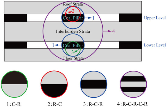
21]. In this situation, the overlapped residual coal pillars are designed at different mining levels [22]. The roof strata, upper pillar, interburden strata, lower pillar, and the floor strata, shown in Figure 1, form a whole bearing system in the underground space. That is, different kinds of sandwiched coal-rock systems exist in ultra-close multiple seam mining. It includes not only the C-R, R-C, and R-C-R sandwiched system, but also the R-C-R-C-R sandwiched system. The safety of ultra-close multiple seam mining is closely associated with the stability of the sandwiched coal-rock system.
With the coupled effects of environmental weathering, mining-induced stress, and other unfavorable factors, catastrophic collapse of sandwiched coal-rock systems in ultra-close multiple seam mining may be induced [23]. A famous collapsing case, which occurred in the Shigetai coal mine of China, was described by Zhu et al [24]. The roof strata-upper pillar-interburden-lower pillar-floor strata system simultaneously collapsed, which induced an abnormal response of strata behaviors. Therefore, further observations about the sandwiched coal-rock system are necessary to provide thorough insights into the progressive failure characteristics and mechanisms. They are significant for revealing the occurrence mechanism of dynamic disasters in ultra-close multiple seam mining.
In this study, the description of the sandwiched coal-rock system is first presented. Four groups of uniaxial compression tests are designed and conducted for different kinds of sandwiched coal-rock specimens (C-R, R-C, R-C-R, and R-C-R-C-R). The mechanical behaviors, electrical resistivity responses, acoustic emission features, and local strain evolutions are observed simultaneously during the loading process to reveal the progressive failure characteristics of the sandwiched coal-rock system. Furthermore, the progressive failure mechanism of the sandwiched coal-rock system is investigated.

2. Description of the Sandwiched Coal- Rock System

The sandwiched coal-rock system is proposed to reveal the interactions between coal pillars and the surrounding strata in ultra-close multiple seam mining. It consisted of multiple coal elements and rock elements. In this section, the experimental coal element, rock element, and sandwiched coal-rock specimen are introduced in detail.

2.1. Coal Element and Rock Element

The testing elements were taken from massive coal and rock blocks in Datong coal basins, Shanxi Province, China. Coal blocks were selected from the No.9 and No.10 coal seams. Rock blocks were obtained from the roof strata, floor strata, and the interburden strata. The lithology was sandstone. To maintain the original state as much as possible, the natural coal and rock blocks were wrapped with plastic film before the preparation of the testing elements. Three different sizes of cylindrical coal and rock elements were mainly prepared for the uniaxial compression tests. The diameter of all the testing elements was 50 mm. The heights of the testing elements were 20mm, 33.33 mm, and 50 mm, respectively. The ratios of the height to the diameter for the testing elements were 0.4, 0.67, and 1, respectively.
According to the methods suggested by the International Society for Rock Mechanics [25], the coal and rock elements were firstly cored along the same orientation to maintain homogeneity. No visible cracks and damages were distributed on the surface of the testing elements. Then, the elements were shaped and polished carefully to satisfy the standards of flatness, verticality, and parallelism. Figure 2 shows a photograph of the experimental coal and rock elements with different heights. For further details of the sizes, coal and rock elements with a height of 25 mm and 100 mm are also presented in Figure 2.
After the preparation of the testing elements, a series of tests was performed to obtain the basic physical and mechanical parameters. As presented in Table 1, the relevant parameters of the experimental elements were determined averagely from three series of tests. The strength of the rock element (H = 100 mm) was 21.7 MPa, while it was 10.4 MPa for the coal element (H = 100 mm).

2.2. Sandwiched Coal-Rock Specimen

A standard sandwiched coal-rock specimen was designed and prepared in this study to perform the uniaxial compressive tests. It was composited together by overlapping the coal elements and rock elements. The number of coal elements and rock elements was m and n, respectively. The total number of the coal elements and rock elements was m + n in the sandwiched specimen.
The diameter of the cylindrical sandwiched coal-rock specimen was 50 mm, in which the height of the coal elements and rock elements was designed to be same. Special super glue was selected as the adhesive material to prepare the sandwiched coal-rock specimen [15]. The thickness of the adhesive material between the interface of the coal element and rock element was very small. Therefore, the height of the cylindrical sandwiched coal-rock specimen was approximately 100 mm. The ratio of the height to the diameter for the sandwiched coal-rock specimen was 2. Before conducting the uniaxial compressive experiments, the prepared sandwiched coal-rock specimens were stored in an incubator with a constant temperature and humidity. As shown in Figure 3, four groups of sandwiched coal-rock specimens were prepared in this uniaxial compressive test, which are described in detail as follows:
(1) The sandwiched coal-rock specimen comprising of an upper coal element (H = 50 mm) and a lower rock element (H = 50 m) was designed to represent the pillar-floor system (Figure 3a), which was termed as C-R. The total number of coal elements and rock elements in the C-R specimen was m + n = 2.
(2) The sandwiched coal-rock specimen comprising of an upper rock element (H = 50 mm) and a lower coal element (H = 50 m) was designed to represent the roof-pillar system (Figure 3b), which was named R-C. The total number of coal elements and rock elements in the R-C specimen was m + n = 2.
(3) The sandwiched coal-rock specimen comprising of an upper rock element (H = 33.33 mm), a interburden coal element (H = 33.3 mm), and a lower rock element (H = 33.33 m) was designed to reveal the roof-pillar-floor system (Figure 3c), which was defined as R-C-R. The total number of coal elements and rock elements in the R-C-R specimen was m + n = 3.
(4) The sandwiched coal-rock specimen comprising of three rock elements (H = 20 mm) and two coal elements (H = 20 m) were designed to express the roof-upper pillar-interburden-lower pillar-floor system in ultra-close multiple seam mining (Figure 3d), which was described as R-C-R-C-R. The total number of coal elements and rock elements in the R-C-R-C-R specimen was m + n = 5.
At least three testing samples were composited and prepared for each group of sandwiched coal-rock specimens. The basic physical parameters and composition forms of the experimental sandwiched coal-rock specimens are shown in Table 2.

3. Experimental Methods

The mechanical behaviors, electrical resistivity responses, acoustic emission features, and local strain evolutions of the sandwiched coal-rock specimens were designed to be monitored. The related experimental methods in this study mainly included the experimental system and procedures.

3.1. Experimental System

The experimental system is shown in Figure 4, which mainly includes the uniaxial loading system, electrical resistance testing system, AE monitoring system, and strain testing system. During the failure process of the sandwiched coal-rock specimens, the mechanical behaviors, electrical resistivity responses, AE features, and local strain evolutions were monitored simultaneously by this experimental system.

3.1.1. Uniaxial Loading System

An electro-hydraulic testing machine servo-controlled by a microcomputer was applied to conduct the uniaxial compression experiment in this study. It was composed of a control system, a loading system, and an automatic data acquisition system. The maximum loading capacity was 1000 kN. As shown in Figure 4, two rigid steel loading plates were placed between the loading frame and experimental sandwiched coal-rock specimen. The displacement loading mode was adopted with a strain rate of 0.002 mm/s in the present study. Moreover, the load and deformation of the sandwiched coal-rock specimen was monitored continuously over the whole loading process.

3.1.2. Electrical Resistance Testing System

Electrical resistivity is one of the inherent physical parameters that defines the resistance characteristics of a testing specimen [26]. The electrical resistivity at different loading stages could reveal the failure characteristics of a coal/rock specimen. It is significant for predicting the collapse of dynamic disasters. In the current experiments, sandwiched coal-rock specimens as a whole were viewed as an electrical resistance body.
Generally, the electrical resistivity of a single coal/rock body is determined [27] by Equation (1):
ρ = R · S H = R · π r 2 H
where ρ is the electrical resistivity of a single coal/rock body (Ω·m); R is the electrical resistance of a single coal/rock body (Ω); S is the effective cross-sectional area of a single coal/rock body (m2); H is the height of a single coal/rock body (m); and r is the radius of a single coal/rock body (m).
Meanwhile, the electrical resistivity is usually regarded as being equal for coal/rock elements with the same diameter and height [28]. Therefore, the electrical resistivity of a sandwiched coal-rock specimen can be calculated by the following equation:
ρ h = R h · S h H h = ( m R c + n R r ) · S h m H c + n H r = ( m R c + n R r ) · π r 2 m H c + n H r
where ρh is the electrical resistivity of a sandwiched coal-rock specimen (Ω·m); Rh is the electrical resistance of a sandwiched coal-rock specimen (Ω); Sh is the effective cross-sectional area of a sandwiched coal-rock specimen (m2); Hh is the height of a sandwiched coal-rock specimen (m); Rc is the electrical resistance of the coal element (Ω); Rr is the electrical resistance of the rock element (Ω); Hc is the height of the coal element (m); Hr is the height of the rock element (m); m is the number of coal elements in the sandwiched coal-rock specimen; n is the number of rock elements in the sandwiched coal-rock specimen; and r is the diameter of the sandwiched coal-rock specimen (m).
To measure the electrical resistance of sandwiched coal-rock specimens, a two-electrode insulation resistance testing system was adopted in this experimental system. It was mainly composed of resistance testing holders, copper electrodes, insulation boards, a data acquisition instrument, and an analysis software. As shown in Figure 4, copper electrodes were fixed symmetrically at the upper and lower ends of the sandwiched coal-rock system. They were sandwiched between the insulation boards and the testing coal-rock specimen. Resistance testing holders were connected with the upper and lower copper electrodes, which were also linked with the data acquisition instrument. The measuring deviation was within 1%. The maximum testing resistance was 1012Ω and the data acquisition frequency was 5 Hz.

3.1.3. AE Monitoring System

An 8-channel AE monitoring system was utilized to capture the real-time evolution of AE energy and the spatial location of AE events. As shown in Figure 4 and Figure 5, it consisted of AE sensors, AE pre-amplifiers, an AE data acquisition instrument, and an AE analysis software.
In this experiment, four cylindrical AE sensors with a diameter of 18 mm were mounted slightly on the surface of the sandwiched coal-rock specimen with tape to acquire the AE signals and parameters. According to the method suggested by International Society for Rock Mechanics for laboratory AE monitoring [28], the arrangement position of AE sensors was shown in Figure 5. The linking line of sensor 1 and sensor 2 was vertical mutually to that of sensor 3 and sensor 4. To enhance the connections and improve signal transmission, silicon grease was applied as the coupling agent between the AE sensors and the sandwiched coal-rock specimen. The data acquisition frequency and amplitude threshold were set at values of 2.5 MHz and 40 dB, respectively.

3.1.4. Strain Testing System

Although only local deformation can be measured by strain gauge rosettes due to space limitations, they are still able to reflect the failure characteristics of a sandwiched coal-rock specimen under compressive loading [29]. A strain testing system was applied throughout the experiments to reveal the local strain characteristics of sandwiched coal-rock specimens. It consisted of a data acquisition system, bi-channel strain gauge rosettes, lead wires, and data analysis software. In the uniaxial experiments, each bi-channel strain gauge rosette was composed of a horizontal strain gauge and a longitudinal strain gauge. The size of the strain gauge was 10 mm in length and 2.5 mm in width. The sensitivity was 10−6 ε. Prior to the experiment, one pair of strain gauge rosettes was attached by silastic glue at the central position of each coal and rock element. During the failure process, the axial and lateral strains of each coal/rock element were observed continuously.

3.2. Experimental Procedures

The procedures of the uniaxial compression test are described in the following steps: (1) The coal and rock elements with different size were prepared firstly. (2) The coal and rock elements were composited to form the standard sandwiched coal-rock specimen. (3) The AE sensors, preamplifiers, data acquisition instrument, and analysis software were connected. The AE sensors together with silicon grease were attached slightly on the surface of the polished sandwiched coal-rock specimen. (4) The resistance testing holders, data acquisition instrument, and analysis software were subsequently linked. The insulation board and copper electrode were positioned successively in the center of the lower loading plate. (5) The data acquisition system, strain gauge rosettes, and lead wires were linked. Afterwards, the strain gauge rosettes were fixed by silastic glue on the surface of each coal and rock element. (6) The test sandwiched coal-rock specimen with AE sensors and strain gauge rosettes was put on the surface of the lower copper electrode. The upper copper electrode and insulation board were placed on the top surface of the sandwiched coal-rock system. (7) Then, the upper loading plate was moved downwards to slightly touch the upper insulation board. Additionally, resistance testing holders were linked with the upper and lower copper electrodes. (8) The uniaxial loading system, resistance testing system, AE monitoring system, and strain testing system were turned on simultaneously to collect the stress-strain curve, electrical resistance data, AE parameters, and local strains until the overall failure of the sandwiched coal-rock specimen.

4. Experimental Results

In this section, the experimental results for different kinds of sandwiched coal-rock specimens are presented. The mechanical behaviors, AE features, electrical resistivity responses, and local strain evolution are analyzed in detail to reveal the progressive failure characteristics.

4.1. Mechanical Behaviors

During the whole loading process, the stress-time relations for different kinds of sandwiched coal-rock specimens are shown by the dark curves in Figure 6. According to the bearing characteristics, the overall tendency of the mechanical behaviors was basically similar. It can be divided into four stages. Stage I was the nonlinear growth stage of the bearing capacity. Stage II was the linear growth stage of the bearing capacity. Stage III was the yielding growth stage of the bearing capacity. Stage IV was the weakening stage of the bearing capacity. A thorough description of the mechanical behaviors is presented as follows (see Figure 6):
(1) The axial stress of C-R, R-C, R-C-R, and R-C-R-C-R grew during stage I in an up-concaved form (see Figure 6a–d). Original pores and cracks inside the testing specimen, especially in the coal elements, were enclosed gradually with the rising stress. The compaction deformation was dominant at stage I. As a result, the nonlinear growth of the bearing capacity was presented for different kinds of sandwiched coal-rock specimens.
(2) As presented in Figure 6, the bearing stress of the sandwiched coal-rock specimen increased linearly during stage II. The sandwiched coal-rock specimens mainly experienced elastic deformation. The duration of stage II was approximately 460 s, 440 s, 300 s, and 360 s for C-R, R-C, R-C-R, and R-C-R-C-R, respectively.
(3) For different kinds of sandwiched coal-rock specimens, the bearing capacity began to depart from the linear growth. As shown in Figure 6, weakening growth of the bearing stress was monitored for different kinds of sandwiched coal-rock specimens. It indicated the arrival of the yielding growth stage. Plastic deformation was dominant at stage III. It was noted that a little stress fluctuation was observed for C-R and R-C-R-C-R (see Figure 6a,d). However, the overall yielding growth of the bearing load was not influenced. Stage III proceeded until the appearance of peak stress. It was the arrival of the limit bearing capacity for sandwiched coal-rock specimens. As shown in Figure 6a,b, the peak stress was 26.24 MPa and 27.88 MPa, respectively. Apparently, the limit bearing capacity for C-R and R-C was almost equivalent in value. The limit bearing stress of R-C-R, shown in Figure 6c, was approximately 17.15 MPa. It was 12.98 MPa for R-C-R-C-R, as shown in Figure 6d.
(4) After the peak stress, the bearing load of the sandwiched coal-rock specimens tended to decrease as a whole. At the initial period of stage IV, the weakening rate of the bearing capacity was relatively small. Subsequently, a large drop of the bearing stress occurred within a short time. It indicated that the sandwiched coal-rock specimens experienced intense damage. The continuity and integrity were seriously destructed. It was worth noting that stage IV for C-R, R-C-R, and R-C-R-C-R was relatively longer than that of R-C. The bearing stress of R-C specimen declined within a very short time during stage IV, which could be explained by the earlier instability of the coal element at the lower position. The bearing capacity of R-C was lost sharply as soon as the coal element failed.

4.2. Electrical Resistivity Responses

Real-time electrical resistance for different kinds of sandwiched coal-rock specimens was monitored throughout the unaxial compressive experiments. Then, the electrical resistivity was calculated based on Equation (1). The green curves in Figure 6 represent the response of the electrical resistivity for C-R, R-C, R-C-R, and R-C-R-C-R, respectively.
Before loading, the initial electrical resistivity for C-R, R-C, R-C-R, and R-C-R-C-R was 1.67 MΩ·m, 1.67 MΩ·m, 1.42 MΩ·m, and 1.55 MΩ·m, respectively. With the development of compaction deformation, the electrical resistivity of the sandwiched coal-rock specimens decreased gradually although a slight fluctuation was observed during stage I (see Figure 6). The enclosure of natural micro-pores and cracks could explain this phenomenon, which resulted in the generation of new electrical channels [10]. Under the coupled effects of the original and newborn electrical channels, the overall conductive capability of the sandwiched coal-rock specimens was improved.
At stage II, the declining tendency of the electrical resistivity continued to be monitored for different kinds of sandwiched coal-rock specimens. However, the declining rate weakened gradually. It indicated that the conductive channels in the defective areas were damaged locally during the elastic deformation process.
The electrical resistivity of the sandwiched coal-rock specimens was maintained at a relatively small value during stage III. An overall decreasing tendency was shown along with the yielding growth of the bearing capacity. A remarkable increase of the electrical resistivity appeared at the end of stage III when the peak bearing stress was captured. This was attributed to the generation of macro-cracks, which further induce serious damage to the electrical conductive channels.
When the axial stress evolved into stage IV, the electrical resistivity of the sandwiched coal-rock specimens seemed to be chaotic due to the uncertainty of crack propagation and the diversity of the failure mode. As presented in Figure 6a, sudden drops and growth of the electrical resistivity were captured at stage IV for C-R. A general increasing tendency of the electrical resistivity is shown in Figure 6b,c for R-C and R-C-R. As shown in Figure 6d, the electrical resistivity for R-C-R-C-R declined initially with some fluctuations, while it tended to grow at the end of stage IV.

4.3. AE Characteristics

AE features are not only described by the evolution of AE energy quantitatively [30], but are also revealed by the distribution of AE events qualitatively [31]. The red and blue curves in Figure 6 represent the AE energy and accumulative AE energy of the sandwiched coal-rock specimens at different loading times. The AE events distributions are also shown in Figure 7, Figure 8, Figure 9 and Figure 10 for different kinds of sandwiched coal-rock specimens during the loading process. The letters shown in Figure 7, Figure 8, Figure 9 and Figure 10 correspond to the purple markers and time slices sown in Figure 6.

4.3.1. Evolution of AE Energy

The overall evolution of the AE energy and accumulated AE energy for different kinds of sandwiched coal-rock specimens is presented in Figure 6. Detailed descriptions of the AE energy and accumulated AE energy at different load times are as follows.
During stage I, the AE energy of the sandwiched coal-rock specimens was maintained at relatively small values with little fluctuation (see Figure 6). It was primarily released due to the closure effect of the initial pores and cracks. With the increase of loading time, the AE energy was accumulated slightly at a very slow rate.
The output of AE energy at stage II was mainly attributed to the generation and expanding of micro-cracks in the sandwiched coal-rock specimens. It was activated gradually along with the linear growth of the bearing capacity. Correspondingly, the accumulated AE energy also presented a gentle smooth rising tendency.
The AE behavior of sandwiched coal-rock specimens became more intense at stage III. Massive AE energies were released at this stage. It resulted in the fast growth of accumulated AE energy. The exacerbation of internal damage and the acceleration of the micro-cracks’ expansion provides an explanation for this phenomenon. It is worth noting that the sudden growth of AE energy was observed along with stress drops in Figure 6a,d. As soon as the appearance of the maximum bearing stress, peak AE energy was recorded. As presented in Figure 6, the maximum values of AE energy for C-R, R-C, R-C-R, and R-C-R-C-R were approximately 35.45 × 10⁴ mV·mS, 41.68 × 10⁴ mV·mS, 25.31 × 10⁴ mV·mS, and 36.74 × 10⁴ mV·mS, respectively. The fastest growth rate of accumulated AE energy at this point was also captured for different kinds of sandwiched coal-rock specimens.
Due to the exacerbation of internal damage and the generation of macro-cracks, the release of AE energy for the sandwiched coal-rock specimens was still active during stage IV. However, it tended to be chaotic as a whole. As shown Figure 6, the increasing tendency of accumulated AE energy was continuously monitored during stage IV.

4.3.2. Distribution of AE Events

AE energy reflects the global acoustic information about different kinds of sandwiched coal-rock specimens. However, it cannot be applied to describe the local acoustic characteristics of coal elements and rock elements. To provide deeper insight into the progressive failure characteristics of sandwiched coal-rock specimens, the three-dimensional (3D) distribution of AE events was also investigated in detail. This reflects the spatial evolution of micro-cracks and internal damages inside the coal elements and rock elements at different heights [10].
Figure 7 shows the 3D distribution of accumulated AE events inside the C-R specimen during the loading process. Under the compaction effects at stage I (see Figure 7a,c), earlier AE events appeared randomly on both the coal element (50–100 mm) and rock element (0–50 mm). The number of AE events inside the C-R specimen increased slightly during the elastic deformation process at stage II, which were mainly caused by the initiation and propagation of micro-cracks at the height of 50–100 mm. As shown Figure 7d–g, AE events were mostly inside the coal element. The distribution space of AE events in this area also expanded progressively from the top section to the bottom section. Furthermore, the number and density of AE events inside the coal element (50–100 mm) were apparently more than those in the rock element (0–50 mm). That is, the coal element in the C-R specimen primarily experienced the micro-damage at stage II due to its lower strength. In terms of the rock element in the C-R specimen, little internal damage appeared and AE events were random at this stage. It is worth noting that several AE events were spread across the interface of the coal element and rock element at the later period of stage II (see Figure 7g). However, most of them were located at the left-top corner of the rock element. This indicates that local damage of the rock element was induced by the damage to the coal element. At stage III, the number of AE events in Figure 7h,i grew significantly inside the C-R specimen. Corresponding to the intensive release of accumulated energy in Figure 6a, the AE events were almost distributed throughout the coal element. This indicates that the internal damage inside the coal element was exacerbated during stage III. Furthermore, the AE events scattered at the top corner of the rock element also increased in number. Both the distribution area and density were enlarged. When it turned into stage IV, the number of AE events inside the C-R sandwiched coal-rock specimen continued to grow (see Figure 7i,j). This was attributed to the connection of macro-cracks, the formation of the sliding plane, and the dislocation of material particles. AE events inside the coal element were greater than those in the rock element. The distribution space of AE events in the rock element was still centralized near the top corner, which demonstrated the induced damage was not spread across the entire rock element at stage IV.
The 3D distribution of the accumulated AE events inside the R-C specimen at different loading times is presented in Figure 8. As a whole, AE events in Figure 8a–d started to generate both on the coal element (0–50 mm) and the rock element (50–100 mm) at stage I. This was attributed to the closure of natural pores and cracks inside the specimen. With the increase of the loading time, a more rapid increase of AE events was monitored inside the coal element. The distribution space of AE events also expanded progressively inside the coal element. As shown in Figure 8e–h, primary AE events were located at the height of 0–50 mm (coal element) during the elastic deformation stage. The total number of AE events inside the rock element also increased. However, the growth rate was obviously less than that in the coal element. At stage III, a drastic increase of AE events was observed inside the coal element, which quickly distributed throughout the whole coal element (see Figure 8h,i). This is evidence of the exacerbated damage inside the coal element. Moreover, the micro-damage at this stage propagated across the interface between the rock element and the coal element. Many AE events were also found at the bottom corner of the rock element. After the peak stress in Figure 8j, the AE events maintained the increasing tendency inside the R-C specimen. The growth rate was fast at the height of 0–50 mm, while it was relatively weak at the height of 50–100 mm. It should be noted that dense AE events at stage IV were still scattered inside the coal element. Only rare AE events were distributed at the local areas of the rock element.
For the R-C-R specimen, the 3D distribution of AE events during the compressive process is displayed in Figure 9. The AE events first appeared at the height of 33.33–66.67mm. As shown in Figure 9a–c, they were almost located inside the coal element during stage I. No AE events were captured inside the upper and lower rock elements. At stage II, the number of AE events was mainly accumulated inside the coal element, as shown in Figure 9d–h. The distribution space also propagated gradually at the height of 33.33–66.67 mm. At this stage, a few AE events also appeared near the top and bottom coal-rock interfaces. This demonstrates that the micro-damage that stemmed from the coal element had interconnected and spread into the rock element. Afterwards, AE events increased continuously at a height of 33.33–66.67 mm, as shown in Figure 9i,j. The coal element experienced the most damage at the yielding stage. The distribution density of AE events inside the rock elements also gathered slightly at stage III. Ultimately, a weak increasing tendency of AE events inside the R-C-R specimen was presented at stage IV. This can be seen in Figure 9k–n. Massive AE events were concentrated on the coal element. However, the damage was rarely scattered inside the rock element without the formation of a distinct nucleation belt.
The distribution of AE events in the R-C-R-C-R specimen during the loading process is revealed in Figure 10. Apparently, the AE events first originated at a height of 20–40 mm at stage I (see Figure 10a,b). Then, sporadic AE events were captured at a height of 60–80 mm. At stage II, the AE events, as shown in Figure 10c,d, were dominantly gathered and generated inside the coal elements. A small amount of AE events also appeared randomly at a height of 40–60 mm, which indicates that the released damage energy spread to the rock element. Subsequently, the number of AE events at stage III not only gathered inside the coal elements, but also in the rock elements (see Figure 10e,f). The growth rate in the coal elements was continuously greater than that in the rock elements. Consequently, the distribution area and density of AE events in the coal elements further thrived at stage IV. The concentration of AE events in the interburden rock element is shown in Figure 10g–j. This provides evidence that damage occurred to the rock element at a height of 40–60 mm.

4.4. Local Strain Development

The local stain development for different kinds of sandwiched coal-rock specimens is presented in Figure 11a–d. To gain a deeper understanding of the local strain, the time-stress curves of sandwiched specimens are also shown by the black curves. A positive value of local strain means the lateral strain measured by the longitudinal gauge, while a negative value of local strain means the axial strain measured by the horizontal gauge.
The local strain of the coal element (50–100 mm) and rock element (0–50 mm) in the C-R specimen at different loading times is shown in Figure 11a. The axial strain of the coal element and rock element increased at stage I and II. As a whole, the growing rate of the coal element was more rapid than that of the rock element. It is obvious that the axial strain value of the rock element was smaller than that of the coal element. The lateral strain of the coal element was basically close to that of the rock element during the initial loading process. A significant difference between the lateral strains of the coal element and rock element gradually appeared at the later period of stage II. The lateral strain of the coal element was almost twice that of rock element at the end of stage II. When the axial stress yielded at stage III, the growth rate of the local strain was enhanced for the coal element. When the peak stress of the C-R specimen was observed, the axial strain of the coal element and rock element was −11.94 × 10⁻³ and −3.34 × 10⁻³, respectively. The lateral strain of the coal element and rock element was +6.78 × 10⁻³ and +2.98 × 10⁻³, respectively. At the beginning of stage IV, the axial strain of the coal element accelerated. Then, it tended to decrease from 800 s. The lateral strain of the coal element increased apparently throughout stage IV. For the rock element, both the axial strain and lateral strain started to decrease after the peak stress. The declining rate was almost opposite to the growth rate at stage II and stage III. It suggested that the rock element caused a partial recovery of strain at stage IV, which was induced by the collapse of the coal element.
A similar evolution tendency of the local strain was presented for the R-C sandwiched specimen, which is shown in Figure 11b. The axial strain of the coal element (0–50 mm) was always larger than that of the rock element (50–100 mm) from stage I to stage III. Continuous growth of the axial strain was observed on the coal element after peak stress. With the sudden decrease of the bearing stress, a sharp decrease of the axial strain also appeared on the coal element. When the axial stress evolved into stage IV, the axial strain of the rock element tended to decrease slightly. Moreover, the lateral strains of the coal element and rock element were nearly synchronous at stage I and the initial period of stage II. After, the coal element generated a larger lateral strain than the rock element. The growth of the lateral strain continued throughout stage III and stage IV for the coal element. A turning point of the lateral strain was captured on the rock element as soon as the appearance of the peak stress. Then, a recovery of the lateral strain appeared on the rock element.
For the R-C-R specimen, the axial strain of the coal element (33.33–66.67 mm) was obviously larger than that of the rock element (0–33.33 mm and 66.67–100 mm) from stage I to stage III (see Figure 11c). The lateral strain of the coal element and rock elements was nearly coincident at stage I. The difference was gradually highlighted when the axial stress turned into stage II. The lateral strain of the coal element was significantly more than that of the rock elements at stage II and stage III. It should be noted that the local strain of the upper and lower rock elements was not consistent after stage II. It was attributed to the heterogeneity of the rock elements. The original defects in the different rock elements were not exactly same. At stage IV, the earlier decreasing of the local strain appeared slightly in the rock elements, which indicates the recovery of the local strain. At this moment, the local strain on the coal element was still increasing. When the loading time was about 725 s, there was a sudden decrease in the local strain for the coal elements. It predicted the rupture of the coal element. Ultimately, a little fluctuation of the local strain was apparent in the coal element.
Figure 11d shows the local strain of the coal elements and rock elements at different heights in the R-C-R-C-R specimen. With the increase of the loading time, the local strains of the coal elements and rock elements presented a gradual increasing tendency from stage I to stage III. As shown in Figure 11d, the axial strain and lateral strain of the rock elements (0–20 mm, 40–60 mm, and 80–100 mm) were almost the same from stage I to stage III. Additionally, little differences were also observed for the coal element at the height of 20–40 mm and 60–80 mm. As a whole, the growth rate of the local strain on the coal elements was faster than that of the rock elements. Consequently, the local strains generated on the coal elements were also larger than those of the rock elements. After the peak stress of the R-C-R-C-R specimen, the rebounding of local strains was observed on the rock elements at the height of 0–20 mm and 80–100 mm. However, the rock element (40–60 mm) was an exception. The lateral strain was still increasing at stage IV. Although several chaotic jumps and drops were found, the overall growth of the axial strain was also presented for the rock element (40–60 mm) at stage IV. Coal elements at the height of 20–40 mm and 60–80 mm experienced further damage at stage IV. The growth of the lateral strain was maintained at stage IV. The axial strain of the coal elements was not stable as a whole. Initially, it increased gradually. With the sudden decrease of the bearing stress, a decrease of the axial strain for the coal elements (20–40 mm and 60–80 mm) successively appeared at 1100 s and 1250 s.
Based on the mechanical behaviors, electrical resistivity responses, AE characteristics, and local strain evolution, the failure characteristics for different kinds of sandwiched coal-rock specimens can be summarized as follows: (1) Four stages were observed during the progressive failure process of sandwiched coal-rock specimens, i.e., stage I: Nonlinear growth stage of the bearing capacity; stage II: Linear growth stage of the bearing capacity; stage III: Yielding growth stage of the bearing capacity; and stage IV: Weakening stage of the bearing capacity. (2) The response of the electrical resistivity and the evolution of AE energy were in good agreement with the mechanical behaviors at different stages, which could be used to reveal the global failure characteristics of sandwiched coal-rock specimens. The distribution of AE events and the development of local strain provide further insight into the local failure characteristics of coal or rock elements in the sandwiched specimens. (3) AE events generated earlier in coal elements, which expanded along with the increase of the loading time. Until the failure of sandwiched coal-rock specimens, almost all areas of coal elements were distributed with AE events. AE events also propagated across the coal-rock interfaces, thus local damage of rock elements was induced. For the C-R, R-C and R-C-R specimens, the AE events were distributed in the local areas of rock elements. For the R-C-R-C-R specimen, the upper and lower rock elements experienced local damage. However, the AE events were scattered throughout the whole interburden rock elements. (4) Local strain of coal elements and rock elements in the sandwiched specimen were not always coordinated during the whole failure process. Unbalanced deformation characteristics were apparently revealed. Compared with the rock element, the growth rate of the axial strain and lateral strain in the coal elements was much faster before the peak stress, which accelerated intense deformation of the coal elements. During the weakening stage of the bearing stress, the local strain of coal elements was continuously stable, while a certain recovery of the local strain was observed on the rock elements.

5. Discussions

A mechanical model of the sandwiched coal-rock specimen is established in this section. Moreover, the progressive failure mechanism of the sandwiched coal-rock specimen is also investigated according to the progressive failure characteristics.

5.1. Unbalanced Deformation Characteristics of Coal Elements and Rock Elements

During the loading process, the axial stress loaded on the coal elements and rock elements is same [2,15]. Due to differences in the elastic modulus (E), a completely different deformation pattern is exhibited by the coal elements and rock elements in sandwiched specimens [14,15]. In the present study, the elastic modulus of coal elements was less than that of rock elements. As a result, the axial strain of coal elements was more than that of rock elements.
Apparently, the unbalanced deformation characteristics of coal elements and rock elements are shown. The local strain of coal elements and rock elements from the laboratory experiments in Figure 11 can be illustrated by the above relationship. Therefore, the progressive failure mechanism of coal elements and rock elements in the sandwiched coal-rock system is significantly different, which is investigated deeply in the following section.

5.2. Progressive Failure Mechanism of the Sandwiched Coal-Rock System

In this section, the initial rupture mechanism of coal elements and the induced damage mechanism of rock elements is investigated in detail. Then, a comprehensive understanding of the progressive failure mechanism of sandwiched coal-rock system is provided.

5.2.1. Initial Rupture Mechanism of Coal Elements

Before the peak axial stress, the local strain of coal elements was much larger than that of rock elements. As a result, micro-cracks and micro-damage were more likely to emerge in the coal elements. Along with the growth of the bearing stress, a great amount of strain energy also accumulated in the coal elements, which was obviously more than that in the rock elements.
Due to the lower UCS, the ultimate bearing stress of coal elements was more easily reached. Softening behaviors were significantly exhibited in the coal elements after the peak stress [8]. The generation and connection of macro-cracks tended to be exacerbated. Progressive dissipation of strain energy stored in the coal elements was induced [32]. Then, the initial rupture of coal elements was observed. During the evolution process, a substantial elastic recovery of deformation was also monitored in the rock elements [33]. The release of the absorbed strain energy in the rock elements was promoted. It could transfer across the coal-rock interfaces and penetrate to the coal elements. Therefore, further rupture of the coal elements appeared due to the compensation of strain energy from the rock elements. That is, the recovery of elastic deformation in the rock elements exacerbated the rupture of the coal elements [10]. After, the structural failure of the coal elements occurred.

5.2.2. Induced Damage Mechanism of Rock Elements

Previous studies showed that coal elements are usually the main rupture damage elements, while rock elements are rarely damaged [14,17]. This is because the UCS of rock elements in these literatures was significantly more than that of coal elements. In some cases, the UCS of rock elements was even three times more the strength of the coal elements [18]. The current research found that not only were the coal elements ruptured, but the rock elements were also damaged in the sandwiched coal-rock system. The following section explains the induced damage mechanism of rock elements in detail.
Dynamic fracture energy was generated along with the development of macro-ruptures in the coal elements [34]. It could propagate from the coal elements into the rock elements within a short time. Then, a certain degree of damage appeared in the rock elements. Due to the higher UCS and E, the propagation speed of the dynamic fracture energy weakened gradually in the rock elements. Correspondingly, the damage degree at different heights of the rock elements was not same. The closer to the coal-rock interface, the more serious the damage was [35]. In contrast, the induced damage in the rock elements was relatively weak in the area far from the coal-rock interface. These associated descriptions could provide an explanation for the damage mechanism of rock elements in the sandwiched coal-rock system. It could also be illustrated by the distribution of AE events in Section 4.3.2.
It is worth noting that whether the rock element is completely damaged also depends on its own height [36]. When the maximum propagation distance of the dynamic fracture energy exceeded the height of the rock element, the damage was distributed throughout the rock elements. Contrarily, the damage was scattered just at the partial area of the rock elements.
For the C-R or R-C specimen, the height of the rock element (50 mm) was obviously more than the maximum propagation distance of the dynamic fracture energy. That is, the transferred dynamic fracture energy was not enough to destroy the entire rock element. The induced damage in the rock elements was mostly distributed near the coal-rock interface. As shown in Figure 7 and Figure 8, the damage in the rock element was gathered primarily at a height of 30–50 mm in the C-R specimen, while it was distributed mainly at a height of 50–70 mm in the R-C specimen.
For the R-C-R specimen, the dynamic fracture energy could not only spread into the upper rock element (66.67–100 mm), but could also propagate into the lower rock element (0–33.33 mm). The maximum propagation distance of the dynamic fracture energy was less than the height of the rock element (33.33 mm). Therefore, the damage of the rock elements was relatively small. The AE events in the rock elements were mainly distributed near the upper and lower coal-rock interfaces (see Figure 9).
For the R-C-R-C-R specimen, the dynamic fracture energy generated by the coal element (20–40 mm) expanded into the rock elements at the heights of 0–20 mm and 40–60 mm. The dynamic fracture energy generated by the coal element (60–80 mm) developed into the rock elements at the heights of 40–60 mm and 80–100 mm. That is, the interburden rock element (40–60 mm) received the dynamic fracture energy from the upper and lower coal elements. In this situation, the height of the sandwiched rock elements was just 20 mm. It was less than the total propagation distances of the upper and lower dynamic fracture energy. Therefore, the damage was distributed all over the interburden rock elements (40–60 mm). As shown in Figure 10, massive AE events were also observed at the height of 40–60 mm in the R-C-R-R-R specimen. For rock elements at the heights of 0–20 mm and 80–100 mm, the received dynamic fracture energy was only generated from the adjacent coal element, which was relatively smaller in value. Therefore, the rock elements at the heights of 0–20 mm and 80–100 mm were not scattered fully within the induced damage. Correspondingly, the number of AE events in the upper and lower rock elements (0–20 mm and 80–100 mm) were obviously less than those in the interburden rock element (40–60 mm).

5.2.3. Progressive Failure Mechanism of the Sandwiched Coal-Rock System

The coal elements and rock elements played significant roles in maintaining the long-term stability of the sandwiched system. The progressive failure of the sandwiched coal-rock system was closely associated with the interactions between the coal elements and the rock elements (see Figure 12).
Due to the lower UCS and E, the initial failure usually appeared in the coal elements. With the damage accumulation of coal elements, the recovery of the elastic deformation and the output of the strain energy were also observed in the rock elements. The released strain energy could accelerate the rupture of coal elements. In turn, a large amount of dynamic fracture energy was generated during the rupture process of coal elements, which could propagate into the rock elements. The induced damage then emerged in a certain area of the rock elements. Consequently, the sudden collapsing of sandwiched coal-rock system occurred.

5.3. Implications for Ultra-Close Multiple Seam Mining

The progressive failure characteristics of sandwiched coal-rock specimens are a reflection of the catastrophic collapse of the roof strata-upper pillar-interburden-lower pillar-floor strata system in the ultra-close multiple seam mining. The experimental results are helpful for predicting the long-term stability of overlapped residual coal pillars and the surrounding strata. Some valuable implications can be concluded from this study to guide the safety of ultra-close multiple seam mining, which are presented as follows:
(1) Coal pillars, possessing lower UCS and E values, are damaged much earlier in the sandwiched coal-rock systems. In ultra-close multiple seam mining, overlapped coal pillars should firstly be designed with a proper size to support overburdened strata. Furthermore, the stability of residual coal pillars gradually deteriorates due to the coupled effects of environmental weathering, mining-induced stress, and other unfavorable factors. Additional measures should also be implemented to maintain the long-term stability of residual coal pillars. Backfilling along the coal pillars is one of the potential methods [37]. The backfilling body can not only share the overburdened strata’s weight with the coal pillars, but can also generate a lateral constraint for the coal pillars. Therefore, the backfilling method along the coal pillars is proposed to enhance the overall stability of the sandwiched coal-rock system in ultra-close multiple seam mining.
(2) Surrounding rock strata, with higher UCS and E values, can promote the failure of coal pillars. It provides a further explanation of the mechanisms of coal pillar rupture. In ultra-close multiple seam mining, the stored strain energy in the surrounding rock strata begin to be released when the bearing load of the coal pillar weakens. It can spread from the surrounding rock strata into the coal pillars and accelerate further rupturing of the coal pillars. The more the released strain energy, the more serious the damage to the coal pillar. Therefore, the strain energy of the surrounding rock strata should be eliminated or transferred with related measurements. The pre-cracking technique is an alternative technology to mitigate the propagation of stored strain energy in the surrounding rock strata [38]. Then, the failure of coal pillars can be delayed, and the overall stability of the sandwiched coal-rock system can be maintained for a long time.
(3) Dynamic fracture energy can propagate from the residual coal pillars into the surrounding rock strata. The induced damage then appears in the surrounding rock strata. A certain distance of damage occurs when the dynamic fracture energy spreads into the roof strata or floor strata. That is, the rupture of residual coal pillars can lead to failure of the surrounding rock strata. For the interburden rock strata, it can receive the dynamic fracture energy from the upper coal pillar and lower coal pillar. Therefore, the damage may distribute throughout the interburden rock strata when the total maximum distances of the dynamic fracture energy are more than the heights of the interburden rock strata. In this situation, the stability of interburden strata should be paid much more attention in ultra-close multiple seam mining.

6. Conclusions

In this paper, the sandwiched coal-rock specimen was proposed to investigate the stability of overlapped residual coal pillars and the surrounding rock strata in ultra-close multiple seam mining. A series of uniaxial compression tests were designed and conducted for different kinds of sandwiched coal-rock specimens. The progressive failure characteristics and mechanisms of sandwiched coal-rock specimens were investigated. The following conclusions can be drawn:
(1) The roof strata, upper pillar, interburden strata, lower pillar, and floor strata form a whole bearing system in ultra-close multiple seam mining. The sandwiched coal-rock specimen was firstly proposed to study the stability of overlapped coal pillars and the surrounding rock strata.
(2) The mechanical behavior of the sandwiched coal-rock specimen is mainly divided into four stages during the progressive failure process: Nonlinear growth stage of the bearing capacity, linear growth stage of the bearing capacity, yielding growth stage of the bearing capacity, and weakening stage of the bearing capacity. The response of the electrical resistivity and the evolution of AE energy were in good agreement with the mechanical behaviors at different stages, which can be used to reveal the global failure characteristics of sandwiched coal-rock specimens.
(3) The distribution of AE events and the development of local strain can provide further insight into the local failure characteristics of coal elements or rock elements in sandwiched system. AE events are more likely to generate in coal elements, which can propagate across the coal-rock interfaces and induce the damage of rock elements in a certain area. Similarly, the unbalanced deformation characteristics of coal elements and rock elements were apparently revealed during the progressive failure process of sandwiched coal-rock specimens. The growth rate of local strain on coal elements was much faster than that on rock elements in the initial loading process. A certain recovery of the local strain was observed on the rock elements after the peak stress.
(4) The progressive failure of sandwiched coal-rock specimen was closely associated with the interactions between the coal elements and rock elements. Initial failure usually appeared in the coal elements. In this process, the recovery of the elastic deformation and the output of the strain energy were observed in the rock elements, which can accelerate the rupture of coal elements. In turn, the dynamic fracture energy generated in the rupture process of coal elements can propagate into the rock elements and induce damage of rock elements in a certain area. Consequently, sudden collapse of the sandwiched coal-rock specimen occurred.
(5) The experimental results are helpful for maintaining the long-term stability of sandwiched coal-rock systems in ultra-close multiple seam mining. Overlapped coal pillars should firstly be designed with proper sizes. The backfilling method should be implemented to share the overburdening weight and generate a lateral constraint for the residual coal pillars. Once coal pillars begin to rupture, the pre-cracking technique should be applied to mitigate the propagation of stored strain energy in the surrounding rock strata. Moreover, the interburden rock strata can receive the dynamic fracture energy from the upper coal pillars and lower coal pillars. The stability of interburden rock strata should be given more attention in ultra -close multiple seam mining.

Author Contributions

J.B. carried out the experiments, analyzed the results, conducted the theoretical explanations as well as wrote the manuscript. G.F. conceived and designed the framework. Z.W. assisted to conduct the experiments. S.W. assisted to analyzed the AE data. T.Q. provided some help about the response mechanism of electrical resistivity. P.W. contributed in language polish.

Funding

This research was funded by the Joint Funds of the National Natural Science Foundation of China (U1710258), the National Natural Science Foundation of China (51574172), the Opening Project Fund of State Key Laboratory of Mining Disaster Prevention and Control Co-founded by Shandong Province and the Ministry of Science and Technology (MDPC201701). This work was also funded by the Postgraduate Innovation Project of Shanxi Province (2018BY042). Thanks for all the supporting for this basic research.

Acknowledgments

The authors are very grateful to the editors and reviewers for their kind and invaluable comments. Jinwen Bai also would like to thank the Chinese Scholarship Council for financial support toward his joint Ph.D. at the University of Newcastle, Australia.

Conflicts of Interest

The authors declare no conflict of interest.

References

  1. Feng, G.R.; Zhang, A.; Hu, S.Y.; Cheng, J.W.; Miu, X.Y.; Hao, G.C.; Han, D.D.; Guan, S.W.; Zhao, G.Z. A methodology for determining the methane flow space in abandoned mine gobs and its application in methane drainage. Fuel 2018, 227, 208–217. [Google Scholar] [CrossRef]
  2. Wang, S.Y.; Sloan, S.W.; Huang, M.L.; Tang, C.A. Numerical study of failure mechanism of serial and parallel rock pillars. Rock Mech. Rock Eng. 2011, 44, 179–198. [Google Scholar] [CrossRef]
  3. Jiang, L.S.; Zhang, P.P.; Chen, L.J.; Hao, Z.; Sainoki, A.; Mitri, H.S.; Wang, Q.B. Numerical approach for goaf-side entry layout and yield pillar design in fractured ground conditions. Rock Mech. Rock Eng. 2017, 50, 3049–3071. [Google Scholar] [CrossRef]
  4. Kong, X.G.; Wang, E.Y.; He, X.Q.; Li, D.X.; Liu, Q.L. Time-varying multifractal of acoustic emission about coal samples subjected to uniaxial compression. Chaos Soliton. Fract. 2017, 103, 571–577. [Google Scholar] [CrossRef]
  5. Huang, B.X.; Liu, J.W. The effect of loading rate on the behavior of samples composed of coal and rock. Int. J. Rock Mech. Min. 2013, 61, 23–30. [Google Scholar] [CrossRef]
  6. Yoginder P, C.; Chen, G.; Yu, Z. Effects of the immediate roof-coal pillar-immediate weak floor interaction on coal mine ground control: Laboratory and field characterization studies-Part I. In ISRM 2nd International Specialized Conference on Soft Rocks; International Society for Rock Mechanics and Rock Engineering: Cartagena, Colombia, 2016; pp. 6–7. [Google Scholar]
  7. Hauquin, T.; Gunzburger, Y.; Deck, O. Predicting pillar burst by an explicit modelling of kinetic energy. Int. J. Rock Mech. Min. 2018, 107, 159–171. [Google Scholar] [CrossRef]
  8. Galvin, J.M. Ground Engineering-Principles and Practices for Underground Coal Mining; Springer: Berlin, Germany, 2016; pp. 121–179. [Google Scholar]
  9. Poulsen, B.A.; Shen, B.T.; Williams, D.J.; Huddlestone-Holmes, C.; Erarslan, N.; Qin, J. Strength reduction on saturation of coal and coal measures rocks with implications for coal pillar strength. Int. J. Rock Mech. Min. 2014, 71, 41–52. [Google Scholar] [CrossRef]
  10. Chen, Y.L.; Zuo, J.P.; Liu, D.J.; Wang, Z.B. Deformation failure characteristics of coal–rock combined body under uniaxial compression: Experimental and numerical investigations. Bull. Eng. Geol. Environ. 2018. [Google Scholar] [CrossRef]
  11. Du, F.; Wang, K.; Wang, G.D.; Jiang, Y.F.; Xin, C.P.; Zhang, X. Investigation on acoustic emission characteristics during deformation and failure of gas-bearing coal-rock combined bodies. J. Loss Prevent. Proc. 2018, 55, 253–266. [Google Scholar] [CrossRef]
  12. Liu, J.; Wang, E.Y.; Song, D.Z.; Wang, S.H.; Niu, Y. Effect of rock strength on failure mode and mechanical behavior of composite samples. Arab. J. Geosci. 2015, 8, 4527–4539. [Google Scholar] [CrossRef]
  13. Yin, Y.C.; Tan, Y.L.; Lu, Y.W.; Zhang, Y.B. Numerical research on energy evolution and burst behavior of unloading coal–rock composite structures. Geotech. Geol. Eng. 2018, 27, 295–303. [Google Scholar] [CrossRef]
  14. Zhao, Z.H.; Wang, W.M.; Wang, L.H.; Dai, C.Q. Compression–shear strength criterion of coal–rock combination model considering interface effect. Tunn. Undergr. Sp. Technol. 2015, 47, 193–199. [Google Scholar] [CrossRef]
  15. Liu, X.S.; Tan, Y.L.; Ning, J.G.; Lu, Y.W.; Gu, Q.H. Mechanical properties and damage constitutive model of coal in coal-rock combined body. Int. J. Rock Mech. Min. 2018, 110, 140–150. [Google Scholar] [CrossRef]
  16. Zhao, T.B.; Guo, W.Y.; Lu, C.P.; Zhao, G.M. Failure characteristics of combined coal-rock with different interfacial angles. Geomech. Eng. 2016, 11, 345–359. [Google Scholar] [CrossRef]
  17. Zhang, H.W.; Elsworth, D.; Wan, Z.J. Failure response of composite rock-coal samples. Geomech. Geophysics. Geo-Energy. Geo-Resources. 2018, 4, 175–192. [Google Scholar] [CrossRef]
  18. Guo, H.; Yuan, L.; Shen, B.T.; Qu, Q.D.; Xue, J.H. Mining-induced strata stress changes, fractures and gas flow dynamics in multi-seam longwall mining. Int. J. Rock Mech. Min. 2012, 54, 129–139. [Google Scholar] [CrossRef]
  19. Singh, R.; Singh, S.K.; Kushwaha, A.; Sinha, A. Stability of the parting between coal pillar workings in level contiguous seams during depillaring. Int. J. Rock Mech. Min. 2012, 55, 1–14. [Google Scholar] [CrossRef]
  20. Deutsch, C.V.; Wilde, B.J. Modeling multiple coal seams using signed distance functions and global kriging. Int. J. Coal Geol. 2013, 112, 87–93. [Google Scholar] [CrossRef]
  21. Singh, R.; Ram, S.; Singh, A.K.; Prasad, S.; Buragohai, J. Underground extraction of contiguous coal seams/sections consisting thin parting: A case study. J. S. Afr. Inst. Min. Metall. 2004, 104, 17–27. [Google Scholar]
  22. Wang, J.A.; Shang, X.C.; Ma, H.T. Investigation of catastrophic ground collapse in Xingtai gypsum mines in China. Int. J. Rock Mech. Min. 2008, 45, 1480–1499. [Google Scholar] [CrossRef]
  23. Salmi, E.F.; Nazem, M.; Karakus, M. The effect of rock mass gradual deterioration on the mechanism of post-mining subsidence over shallow abandoned coal mines. Int. J. Rock Mech. Min. 2017, 91, 59–71. [Google Scholar] [CrossRef]
  24. Zhu, D.F.; Tu, S.H. Mechanisms of support failure induced by repeated mining under gobs created by two-seam room mining and prevention measures. Eng. Fail. Anal. 2017, 82, 161–178. [Google Scholar] [CrossRef]
  25. Ulusay, R. The ISRM Suggested Methods for Rock Characterization, Testing and Monitoring: 2007–2014; Springer: Berlin, Germany, 2015. [Google Scholar]
  26. Lü, C.; Sun, Q. Electrical resistivity evolution and brittle failure of sandstone after exposure to different temperatures. Rock Mech. Rock Eng. 2018, 51, 639–645. [Google Scholar] [CrossRef]
  27. Chen, G.Y.; Lin, Y.M. Stress–strain–electrical resistance effects and associated state equations for uniaxial rock compression. Int. J. Rock Mech. Min. 2004, 41, 223–236. [Google Scholar] [CrossRef]
  28. Ishida, T.; Labuz, J.F.; Manthei, G.; Meredith, P.G.; Nasseri, M.H.B.; Shin, K.; Yokoyama, T.; Zang, A. ISRM suggested method for laboratory acoustic emission monitoring. Rock Mech. Rock Eng. 2017, 50, 665–674. [Google Scholar] [CrossRef]
  29. Zhao, Y.L.; Zhang, L.Y.; Wang, W.J.; Pu, C.Z.; Wan, W.; Tang, J.Z. Cracking and stress–strain behavior of rock-like material containing two flaws under uniaxial compression. Rock Mech. Rock Eng. 2016, 49, 2665–2687. [Google Scholar] [CrossRef]
  30. Lin, Q.B.; Cao, P.; Cao, R.H.; Fan, X. Acoustic emission characteristics during rock fragmentation processes induced by disc cutter under different water content conditions. Appl. Sci.-Basel 2019, 9, 194. [Google Scholar] [CrossRef]
  31. Zhang, R.; Dai, F.; Gao, M.Z.; Xu, N.W.; Zhang, C.P. Fractal analysis of acoustic emission during uniaxial and triaxial loading of rock. Int. J. Rock Mech. Min. 2015, 79, 241–249. [Google Scholar] [CrossRef]
  32. Zhang, C.G.; Canbulat, I.; Tahmasebinia, F.; Bruce, H. Assessment of energy release mechanisms contributing to coal burst. Int. J. Min. Sci. Tech. 2017, 27, 43–47. [Google Scholar] [CrossRef]
  33. Wang, J.C.; Wang, Z.H.; Yang, S.L. A coupled macro-and meso-mechanical model for heterogeneous coal. Int. J. Rock Mech. Min. 2017, 94, 64–81. [Google Scholar] [CrossRef]
  34. Buehler, M.J.; Abraham, F.F.; Gao, H.J. Hyperelasticity governs dynamic fracture at a critical length scale. Nature 2003, 426, 141. [Google Scholar] [CrossRef] [PubMed]
  35. Chen, C.H.; Bouchbinder, E.; Karma, A. Instability in dynamic fracture and the failure of the classical theory of cracks. Nat. Phys. 2017, 13, 1186. [Google Scholar] [CrossRef]
  36. Anderson, T.L. Fracture Mechanics: Fundamentals and Applications, 4th ed.; CRC Press: Boca Raton, FL, USA, 2017; pp. 34–50. [Google Scholar]
  37. Sun, Q.; Zhang, J.X.; Zhou, N. Study and discussion of short-strip coal pillar recovery with cemented paste backfill. Int. J. Rock Mech. Min. 2018, 104, 147–155. [Google Scholar] [CrossRef]
  38. Wang, F.T.; Tu, S.H.; Yuan, Y.; Feng, Y.F.; Chen, F.; Tu, H.S. Deep-hole pre-split blasting mechanism and its application for controlled roof caving in shallow depth seams. Int. J. Rock Mech. Min. 2013, 64, 112–121. [Google Scholar] [CrossRef]
Figure 1. Different kinds of sandwiched coal-rock systems involved in ultra-close multiple seam mining. (C-R—Coal pillar and floor strata system; R-C—Roof strata and coal pillar system; R-C-R—Roof strata, coal pillar, and floor strata system; R-C-R-C-R—Roof strata, upper coal pillar, interburden, lower coal pillar, and floor strata system).
Applsci 09 01195 g001
Figure 2. Experimental coal and rock elements. (a) Coal element; (b) rock element.
Applsci 09 01195 g002
Figure 3. Experimental sandwiched coal-rock specimen. (a) C-R; (b) R-C; (c) R-C-R; (d) R-C-R-C-R.
Applsci 09 01195 g003
Figure 4. Experimental system for the sandwiched coal-rock specimen in the uniaxial compressive test. (1—loading plates; 2—insulation boards; 3—copper electrodes; 4—testing sandwiched coal-rock specimen).
Applsci 09 01195 g004
Figure 5. Location of AE sensors in the uniaxial compressive experiment.
Applsci 09 01195 g005
Figure 6. Developments of the axial stress, AE energy, accumulated AE energy, and resistivity for a sandwiched coal-rock system at different loading times. (a) C-R; (b) R-C; (c) R-C-R; (d) R-C-R-C-R.
Applsci 09 01195 g006
Figure 7. Distribution of AE events of C-R sandwiched coal-rock specimen during the loading process. The letters shown in the figure correspond to the purple markers of Figure 7a. (a) 0 s; (b) 100 s; (c) 200 s; (d) 300 s;(e) 400 s; (f) 500 s; (g) 600 s; (h) 700 s; (i) 800 s; (j) 927 s.
Applsci 09 01195 g007
Figure 8. Distribution of AE events of the R-C sandwiched coal-rock specimen during the load process. The letters shown in the figure correspond to the purple markers of Figure 7b. (a) 0 s; (b) 100 s; (c) 200 s; (d) 300 s;(e) 400 s; (f) 500 s; (g) 600 s; (h) 700 s; (i) 800 s; (j) 827 s.
Applsci 09 01195 g008
Figure 9. Distribution of AE events of the R-C-R sandwiched coal-rock specimen during the loading process. The letters shown in the figure correspond to the purple markers of Figure 7c. (a) 0 s;(b) 100 s;(c) 200 s;(d) 250 s; (e) 300 s;(f) 350 s; (g) 400 s; (h) 450 s; (i) 500 s; (j) 525 s; (k) 600 s; (l) 700 s; (m) 800 s; (n) 904 s.
Applsci 09 01195 g009
Figure 10. Distribution of AE events of the R-C-R-C-R sandwiched coal-rock specimen during the loading process. The letters shown in the figure correspond to the purple markers of Figure 7d. (a) 0 s; (b) 300 s; (c) 600 s; (d) 700 s;(e) 800 s; (f) 900 s; (g) 1000 s; (h) 1100 s; (i) 1200 s; (j) 1270 s.
Applsci 09 01195 g010
Figure 11. Evolution of the axial stress and local strain for sandwiched coal-rock specimens at different loading times. (a) C-R; (b) R-C; (c) R-C-R; (d) R-C-R-C-R.
Applsci 09 01195 g011
Figure 12. Interactions between the coal elements and the rock elements in the sandwiched coal-rock system.
Applsci 09 01195 g012
Table 1. Physical and mechanical parameters of experimental coal and rock elements.
TypeDiameter/mmHeight
/mm
Quality
/g
Density
/(kg/m3)
Uniaxial Compressive Strength/(MPa)Elastic Modulus
/(GPa)
Initial Resistivity
/(MΩ·m)
Coal Element49.7820.0663.241.2449.233.280.48
49.8633.4285.301.3134.242.150.82
49.9249.86126.241.2921.421.541.18
49.78100.11249.141.2710.421.342.43
Rock Element49.9120.0891.432.3369.856.240.17
49.8633.26146.572.3643.229.030.22
49.9550.05230.942.4336.7311.180.44
49.8899.97455.302.3121.7212.990.86
Table 2. Physical parameters and composition forms of sandwiched coal-rock specimens.
GroupNo.Diameter
/mm
Height
/mm
Quality
/g
Density
/(kg/m3)
Initial Resistivity
/(MΩ·m)
Composition Forms
R-C0149.97101.12354.081.761.62Rock element (50–100 mm)
Coal element (0–50 mm)
0249.95101.14359.551.811.60
0349.97100.08350.191.761.67
C-R0149.92101.07356.521.801.61Coal element (50–100 mm)
Rock element (0–50 mm)
0249.89101.10353.121.781.63
0349.95101.05350.521.771.68
R-C-R0149.88101.13388.531.971.36Rock element (66.7–100 mm)
Coal element (33.3–66.7 mm)
Rock element (0–33.33 mm)
0249.93100.14387.171.961.39
0349.90100.11390.821.981.40
R-C-R-C-R0149.97101.17375.671.891.45Rock element (80–100 mm)
Coal element (60–80 mm)
Rock element (40–60 mm)
Coal element (20–40 mm)
Rock element (0–20 mm)
0249.93101.19369.451.861.41
0349.90101.20379.021.921.49

