Article

Effects of Magnetic Fields on Quench Characteristics of Superconducting Tape for Superconducting Fault Current Limiter

State Key Laboratory of Electrical Insulation and Power Equipment, Xi’an Jiaotong University, Xi’an 710049, China
*
Author to whom correspondence should be addressed.
Appl. Sci. 2019, 9(7), 1466; https://doi.org/10.3390/app9071466
Submission received: 31 January 2019 / Revised: 31 March 2019 / Accepted: 2 April 2019 / Published: 8 April 2019

Abstract

:
In DC systems, DC resistive type superconducting fault current limiters (R-SFCLs) can respond within a few hundred milliseconds and limit the fault current to a very low level to protect the power equipment in DC systems. The main part of R-SFCLs are superconducting tapes. When short-circuit faults occur in the system, the superconducting tapes will quench and become a large quenched resistor to limit the fault current. The surrounding magnetic fields and the magnetic fields caused by the superconducting tapes itself influence the quench characteristics of the superconducting tapes of R-SFCLs. Thus, the current limiting characteristics of R-SFCLs will also be affected. Until present, very few studies have investigated the effects of magnetic fields on quench characteristics of superconducting tapes for DC R-SFCL. The objective of this paper is to obtain the effects of magnetic fields on quench characteristics of superconducting tapes for DC R-SFCL. Two different kinds of YBa2Cu3O7-δ (YBCO) tapes are studied under a permanent magnetic field of 0, 42.4, 75.9, 122.9 mT, respectively. One is from Shanghai Superconductor Technology Co., Ltd., Shanghai, China, type ST-12-L (named SC_SH) and the other is from American Superconductor Inc. Boston, MA, USA, type 8602 (named SC_8602). The research results show that the magnetic fields influence both the amplitude and the rising rate of the quenched resistance of an SC_SH tape. Under the same magnetic field, both the speed of quenching and the quenching resistance of SC_SH tape are larger than them of SC_8602 when the prospective current exceeds 800 A. Thus SC_SH tape can limit the fault current faster and to a lower level.

1. Introduction

Recently, more and more dispersed energy sources, such as photovoltaic solar power and wind power, have been installed into DC systems. More energy power causes higher short-circuit fault currents in DC systems. Traditional methods of limiting short-circuit fault currents in DC systems, such as adding reactors or partition run of the DC system, have great effects on the flexibility and security of the systems [1]. A DC Resistive Type Superconducting Fault Current Limiter (R-SFCL) can significantly improve the stability of DC systems, especially for the high-power DC network, and helpful to reduce the requirement on a DC circuit breaker for interruption time and dissipated energy stress [2,3,4,5,6,7,8]. A resistive SFCL has a simple structure and excellent performance, so it has a great application value for DC fault current limiting technology [9]. The response time of R-SFCL is within 1 ms [5]. When a short-circuit occurs, the quenching resistance increases quickly to limit the fault current to a very low level [6].
In the normal state, the self-field of superconducting tape coils will influence the critical current of the tapes. A. Polasek considered the influence of the self-field on the critical current of the tapes [10]. S. I. Kopylov said the superconductor’s critical current density largely depends on the local magnetic field [11]. Q. Qiu studied the magnetic field on the characteristics of YBa2Cu3O7-δ (YBCO) tapes of a Flux-Coupling type SFCL [12]. A lot of researchers have investigated the effects of magnetic fields on the critical current of superconducting tapes. Furthermore, it is not easy for the R-SFCL to achieve a simultaneous quench when the superconducting tapes have in-homogeneities caused by manufacturing imperfections. For that reason, K. Tekletsadis [13], D. Ito [14] and Elschner, S. [15] performed studies to achieve uniform quench distribution with a magnetic field. Kato, H. [16] examined the quench behavior of YBCO bulk elements for AC R-SFCL devices with and without an external magnetic field. The experiments showed that the sample element quenched more homogeneously with the quench assist magnet, even if the sample had inhomogeneity along its length. K.B. Park and B.W. Lee [17,18] investigated the quench behavior of YBCO films under magnetic fields. It was revealed that applied magnetic field could induce simultaneous quenches in all YBCO elements when the fault current limiting units connected in series. T. Matsumura [19] applied AC magnetic field to the AC SFCL to get higher resistance only in a current limiting phase. T. Matsumura and S. Lim reported the resistance of the superconducting tapes element and the limiting current capacity of the flux-lock type Superconducting fault current limiter (SFCL) increased by applying the magnetic field into the superconducting tapes’ element and adjusting the inductance ratio between the two coils, which was related with the initial limiting current level [20,21]. S. Lim applied magnetic fields to high temperature superconducting elements to increase both the resistance of superconducting tapes and the current limiting capacity of the flux-lock type SFCL [22,23]. Until now, few researchers have investigated the effects of magnetic fields on the quench characteristics of superconducting tapes for DC R-SFCL. However, the studies mentioned above are under AC. Few studies concerned the current limiting properties of superconducting tapes with magnetic fields for DC.
The objective of this paper is to obtain the effects of static magnetic fields on the quench characteristics of superconducting tapes for DC R-SFCL. Three pairs of permanent magnets were installed between the testing superconducting tapes to generate transverse magnetic fields. The quenched resistance of the superconducting tapes under the transverse magnetic fields of 0, 42.4, 75.9, and 122.9 mT were tested. The magnetic field distribution around the superconducting tapes was simulated by software.

2. SFCLs in a Power System

2.1. The Advantage of the R-SFCL to DC Distribution System

In recent years, DC distributed energy, such as solar energy and wind energy, has been gradually connected to the power system. Considering the security of the power system, the distributed energy should be isolated quickly when the power system fails. In order to decrease the short-circuit current in the power system, the power transport from the distributed energy system to the main power system should be restricted. The application of the R-SFCL is an effective way to decrease the short-circuit current in a system; thus, the power transport from the distributed energy system can be increased significantly. In this way, the installed R-SFCL in the DC system can also promote the development of new energy sources.
For the high voltage source converter (HVSC) DC system, generally, the resistance of the DC fault circuit is very small, which satisfies the underdamping oscillation conditions. Therefore, when the voltage at the DC side oscillates to zero, all the freewheeling diodes in the converter will conduct at the same time. This process is named = the all diodes conducting phenomenon [2]. In addition, this phenomenon will have a negative impact on the AC side.
When the R-SFCL is applied in the DC system, it can not only limit the fault current at the DC side but also limit the overcurrent in the AC side and in the converter station [24]. This is because, after the overcurrent occurs, the R-SFCLs are quenched within 1 ms. The resistance of the R-SFCLs increases very fast to a certain value, which limits the fault current to a relatively low value. Furthermore, the circuit breaker and other power equipment in the system do not need to withstand a high fault current. Figure 1 shows the transient characteristics of the DC fault when the R-SFCLs are applied to the power system [24]. Figure 1 shows that the R-SFCL can limit the fault current to a lower level than the reactive SFCL. After 5 ms, R-SFCL limits the fault current to only around 20% of the fault current. Thus R-SFCL is more suitable for the voltage source converter (VSC) DC system than the reactive SFCL.

2.2. The Requirements to the R-SFCL

The R-SFCL needs to be quenched as soon as possible when the fault current occurs on the DC side. At the same time, the value of the quenching resistance should be large enough to limit the fault current to a safe value. If the quenching speed of SFCL is faster and the resistance value is larger, the overdamping condition can be ensured more easily.
For the R-SFCLs, the magnetic field is one of the factors affecting the quench velocity. In this paper, the effect of the magnetic field on the quench speed of R-SFCL is analyzed. Higher quench velocity and quenched resistance can reduce the rising rate and amplitude of the fault current and increase the reliability of the DC power system.

3. Experimental Step

3.1. Schematic of the Testing Samples

Testing samples are YBCO tapes from Shanghai Superconductor Technology Co., Ltd., Shanghai, China, type ST-12-L (SC_SH) and American Superconductor Inc. Boston, MA, USA, type 8602 (SC_8602). Basic parameters are shown in Table 1. Room resistance was tested by micro-ohmmeter, type C. A 6240.

3.2. Testing Circuit

Test circuit is shown in Figure 2. A limited current (LC) circuit was used to imitate the rising of the DC fault current in the DC system. The 1/2 half of the waveform of current shown in Figure 2b can be used to imitate the rising of the DC fault current. Capacitor C was 100 mF and inductance L was 0.101 mH in Figure 2a. R was the line resistance of the test circuit. Figure 2b shows that the first half waveform of the prospective current when testing superconducting tapes was not installed in the circuit. In this paper, the resistance of the superconductor tape in the 1/2 half-wave is analyzed. The charged voltage of capacitor C was 65 V. the experimental results show that the peak value of prospective current was 1833 A.

3.3. Testing Conditions

New superconducting tapes were used under transverse magnetic fields of 0, 42.4, 75.9, and 122.9 mT. Two kinds of tapes, SC_SH type (Shanghai Superconductor Technology Co., Ltd., Shanghai, China, type ST-12-L) and SC_8602 (American Superconductor Inc. Boston, MA, USA, type 8602), were tested under each magnetic field. The testing superconductor tape was 11 cm length each. Figure 3 shows the experiment’s objective. The superconducting tape was welded with the copper current wire, which was 3 cm width. The voltage leads were connected to both ends of the superconducting tape, respectively. Transverse magnetic fields were generated by two pieces of permanent magnets (Nd2Fe14B), which were put beside the superconductor tape. The magnetic fields applied to superconducting tapes were 0, 42.4, 75.9, and 122.9 mT, respectively. The supporting frame was used to prevent the two permanent magnets bonding together. The supporting frame and the superconducting tape are not in contact with each other. The distance between testing superconducting tapes and the supporting frame (Al material) was 3 cm. Liquid nitrogen was used to keep testing superconducting tape in low temperatures at 77 K. the four-probe method was used to measure the voltage of the testing tape and the transport current.

4. Simulation of Magnetic Fields

The finite element analysis software was used to simulate the flux density around the superconducting tape. Figure 4 shows the simulation model. In all, three pairs of the permanent magnets were used. In each simulation, one pair of permanent magnets was simulated like the experiments. The length and height of the permanent magnets were 100 and 50 mm, respectively. The width of each pair of the permanent magnet was 5, 10, and 20 mm. In the simulation, the distance between the two permanent magnets was 10 cm. Superconducting tape was in the middle of the permanent magnets.
Figure 5a,c,e shows the magnetic fields distribution in two-dimension when the width of each pair of the permanent magnet was 5, 10, and 20 cm, respectively. Figure 5a,c,e shows the top view of Figure 4. At the middle of the figure were superconducting tapes. The magnetic fields at the superconducting tapes were very small. Figure 5b,d,f shows the flux density at the middle of the testing superconducting tapes when the width of each pair of the permanent magnet was 5, 10, and 20 cm, respectively. The flux density was always higher at the middle than at the edge of the testing tapes. Figure 5b,d,f shows that the maximum flux density at the middle of the superconducting tapes was 42.4, 75.9, and 122.9 mT when the width of each pair of the permanent magnet was 5, 10, and 20 cm, respectively. The flux density at the edge of the superconducting tapes was 1.8, 3.1, and 6.47 mT when the width of each pair of the permanent magnet was 5, 10, and 20 cm, respectively.

5. Effects of Magnetic Fields on Quenching Characteristics of Superconducting Tapes

5.1. Waveforms of Experimental Results

The effects of transport current and applied magnetic fields on quenched resistance of two kinds of superconducting tapes were analyzed through experiments. Figure 6a shows the relationship of the limited current, the voltage of the tape, and the quenched resistance of the tape per meter under 75.9 mT of the SC_SH superconducting tapes. The Charged voltage was 45 V. The voltage of the superconducting tapes lagged behind the transport current because of the quench delay. The response time of the testing tape was around 0.1 ms. The peak value of the limited current was 1129.8 A. The peak value of the voltage between the tape was 7.9 V. Resistance per meter at the first peak of current and voltage were 59.2 mΩ/m and 61.1 mΩ/m, respectively. The quenched resistance per meter was calculated by voltage divided by current. In the following results, we compared peak value of the limited current and quenched resistance at the first peak value of the limited current in different situations to investigate the effects of magnetic fields and the transport current on the quenched characteristics of two different kinds of superconducting tapes.
Figure 6b shows the relationship of the limited current, the voltage of the tape, and the quenched resistance of the tape per meter under 75.9 m T of the SC_8602 superconducting tapes. The charged voltage was 45 V. The peak value of the limited current was 1782.0 A, which was 652.2 A higher than the peak value of the limited current of SC_SH. The peak value of the voltage between the tape was 8.5 V, which was 0.6 V higher than the voltage of SC_SH. Resistance per meter at the first peak of current and voltage was 43.8 mΩ/m and 46.2 mΩ/m, respectively. Thus the quenched resistance of SC_SH was higher than SC_8602. Figure 6 shows that, under the magnetic field of 75.9 mT, the current of the SC_8602 was larger than SC_SH. the voltage of the SC_8602 was smaller than SC_SH. Thus, the resistance of the SC_SH was larger than SC_8602 at this time.

5.2. Effects of Magnetic Fields on the Quenched Characteristics of Superconducting Tapes

The same testing method was used to obtain the limited current, the voltage of the tape, and the quenched resistance of the SC_SH and SC_8602 superconducting tapes under magnetic fields of 0, 42.4, 75.9, and 122.9 mT. The relationship between prospecting current, transport current, magnetic fields, and the quenched resistance of superconducting tapes was investigated.
Figure 7 shows the relationship between the prospective current and the quenched resistance per meter of eight testing tapes. The experimental results show that the quenched resistance of these two tapes increased when the prospective current increased. The higher prospective current caused higher Joule heat, which resulted in a higher temperature of the tapes. Thus, the quenched resistance of these two tapes increased when the prospective current increased. When the prospective current was around 300 A, the testing superconducting tapes either did not quench or the quenched resistance was very small, which cannot be tested. Thus, the resistance of the eight superconductor tapes was 0 Ω when the prospective current was lower than 300 A.
The rate of increase was different between the two tapes, as shown in Table 2. For the SC_SH superconducting tapes, when the prospective current changed from 400 A to 900 A, the quenched resistance increased faster than when the prospective current was more than 900 A. For SC_8602 superconducting tapes, the quenched resistance increased faster when the prospective current changed from 620 A to 900 A than when the prospective current was more than 900 A. The rising rate of SC_8602 was low when the prospective current changed from 400 to 620 A.
Table 3 shows the amplitudes of the quenched resistance of two tapes when the prospective current was 1200 A. For SC_SH superconducting types, the quenched resistance increased with the increase of the magnet fields. The magnetic fields influenced both the amplitude and the rising rate of quenched resistance of the SC_SH tape. However, magnetic fields had little effects on the quenched resistance of SC_8602 superconducting types. The quenched resistance of SC_8602 was almost same at different magnetic fields. The superconducting resistance was about 100 mΩ/m at room temperature (25 °C). As shown in Table 3, for the SC_SH, when the current was 1200 A, the resistance was 53 mΩ/m. The resistance was about 62 mΩ/m when the magnetic field was 122.9 mT. The increased ratio of SC_SH is 13.9%. The quenched resistance of the superconducting tapes is in direct proportion to the superconducting length. For a long superconducting tape, the quenched resistance of SC_SH under a magnetic field will increase significantly. However, the magnet field has little effect on the SC_8602.
Figure 8a shows the effects of transport current on the voltage of superconducting tapes. Experimental results shows that the rising rate of the quenched resistance of SC_SH was always higher than SC_8602 under different magnetic fields. The amplitude and the rising rate of voltage of SC_SH increased with the increase of magnetic fields. The effects of the magnetic fields on SC_8602 were smaller than the effects on SC_SH. Figure 8b shows the relationship between the transport current and voltage of the superconducting tapes under the magnetic field of 42.4 mT. The waveforms of SC_SH and SC_8602 can be described as Equations (1) and (2). In Equations (1) and (2), ISC_SH is the transport current through SC_SH, and ISC_8602 is the transport current through SC_8602. USC_SH is the voltage of SC_SH, and USC_8602 is the voltage of SC_SH:
USC_SH = 5.099 exp (ISC_SH/1261) − 5.7 (0 < ISC_SH < 1500 A)
USC_8602 = 1.67 exp (ISC_8602/982) − 2.05 (0 < ISC_8602 < 2000 A).
Figure 9 shows the relationship between the peak value of the prospective current and the peak value of the limited current of the two tapes under the magnetic field of 122.9 mT. The dots in Figure 9 are taken from experimental results, and the lines are linearly fit lines of the dots. The limited current increased almost linearly between SC_SH and SC_8602 when the prospective current increased. The limited current of SC_8602 was higher than SC_SH due to its smaller quenched resistance. The relationship between the prospective current and the limited current was similar in other testing magnetic fields such as 42.4 and 75.9 mT.

6. Conclusions

The magnetic fields influence the quenched resistance characteristics of superconducting tapes of R-SFCL, thereby influencing the current-limiting properties of R-SFCL. This paper investigated the effects of magnetic fields on the quench characteristics of two different kinds of YBCO tapes of DC R-SFCL. The testing YBCO tapes were type ST-12-L, from Shanghai Superconductor Technology Co., Ltd, Shanghai, China (named SC_SH), and type 8602, from American Superconductor Inc. MA, Boston, USA, (named SC_8602). The applied transverse magnetic fields to the testing superconducting tapes were 0, 42.4, 75.9, and 122.9 mT.
(1)
The magnetic fields influenced both the amplitude and the rising rate of the quenched resistance of the SC_SH tape.
(2)
When the prospective current was 1200 A, the quenched resistance of SC_SH superconducting types increased with an increase of the magnet fields. However, the magnetic fields had little effect on the quenched resistance of the SC_8602 superconducting types.
(3)
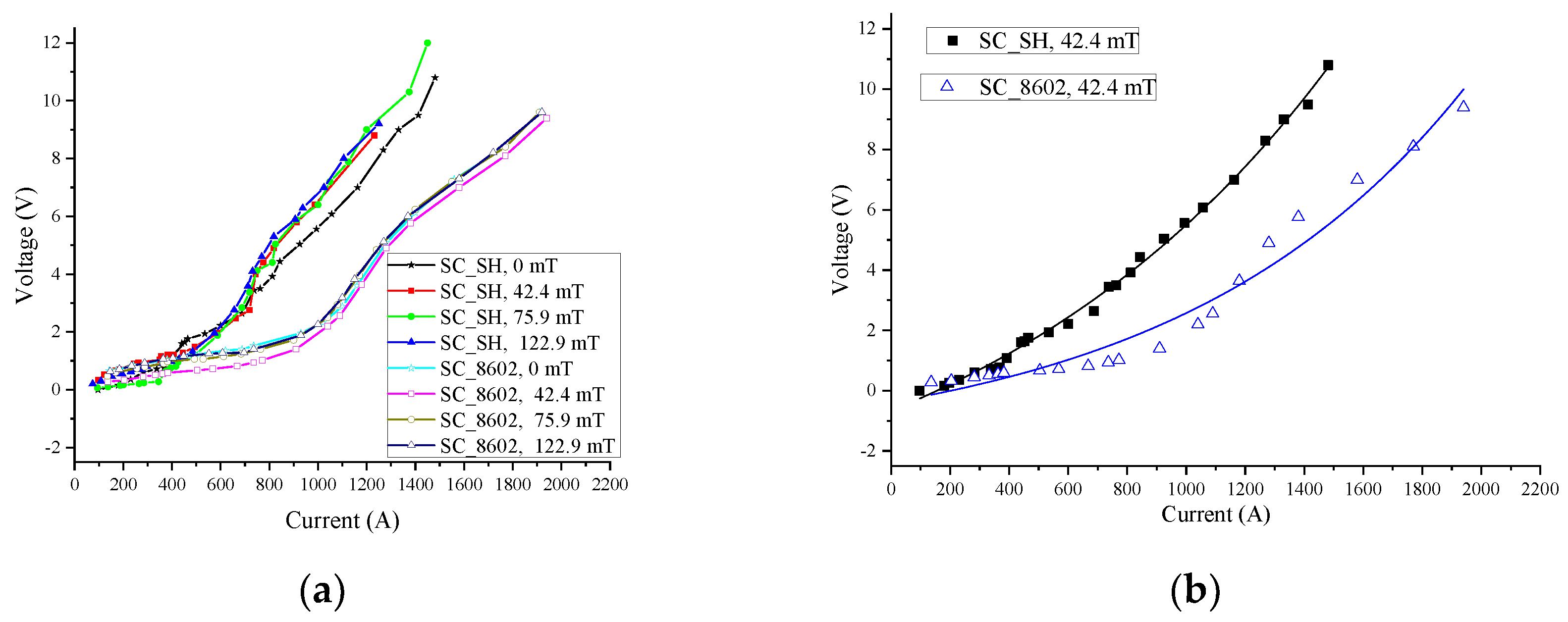
The effects of the transport current on the voltage of the two kinds of tapes increased with exponential growth. The voltage between the SC_SH was higher than the SC_8602 under the same transport current.
(4)
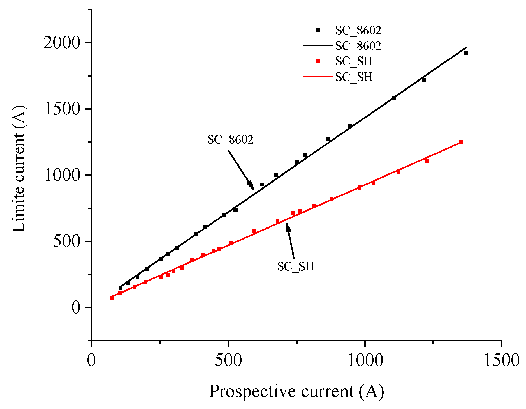
Under the same magnetic fields, both the rising rate and the amplitude of quenched resistance of SC_SH were higher than that of SC_8602 when the prospective current exceeded 800 A. Thus, SC_SH can limit the current quicker and to a lower level than SC_8602.
(5)
The SC_SH tapes were more sensitive to the magnetic field. The magnetic field can prevent a local hot spot in the YBCO tapes, which may cause burnout. Furthermore, the R-SFCL with SC_SH tapes could achieve a more uniform quench distribution with magnetic fields.
In the DC system, the R-SFCLs could not only protect the DC side but also protect the AC side and the converter station in the system. The SC_SH tape has a faster rising rate of quenched resistance and a larger resistance amplitude under the influence of magnetic fields. Thus, SC_SH is more available for R-SFCL to reduce the fault current to a lower level and protect the circuit breakers and other equipment in power systems.

Author Contributions

B.X., L.G. contribute to the experiments, simulations and written of the paper. M.J. contribute to improve the English of the paper. Z.L., Y.G., J.W. and S.Y. contribute to guide this research work.

Funding

This research was funded by the Chinese National Program on Key Basic Research Project (973 Program), grant number 2015CB251005, and the National Natural Science Foundation of China, grand number 51877166.

Conflicts of Interest

The authors declare no conflict of interest.

References

  1. Liang, C.; Li, C.; Zhang, P.; Song, M.; Ma, T.; Zhou, T.; Ge, Z. Winding Technology and Experimental Study on 500 kV Superconductive Fault Current Limiter. IEEE Trans. Appl. Supercond. 2018, 28, 5601105. [Google Scholar] [CrossRef]
  2. Yang, J.; Fletcher, J.E.; O’Reilly, J. Short-circuit and ground fault analyses and location in VSC-based dc network cable. IEEE Trans. Ind. Electron. 2012, 59, 3827–3837. [Google Scholar] [CrossRef]
  3. Lee, J.G.; Khan, U.A.; Lee, H.Y.; Lee, B.W. Impact of SFCL on the four types of HVDC circuit breakers by simulation. IEEE Trans. Appl. Supercond. 2016, 26, 5602606. [Google Scholar] [CrossRef]
  4. Xiang, B.; Liu, Z.; Wang, C.; Nan, Z.; Geng, Y.; Wang, J.; Yanabu, S. DC Interrupting with Self-excited Oscillation Based on Superconducting Current-Limiting Technology. IEEE Trans. Power Deliv. 2018, 33, 529–536. [Google Scholar] [CrossRef]
  5. Xiang, B.; Liu, Z.; Geng, Y.; Yanabu, S. DC Circuit Breaker Using Superconductor for Current Limiting. IEEE Trans. Appl. Supercond. 2015, 25, 5600207. [Google Scholar]
  6. Xiang, B.; Yang, K.; Tan, Y.; Liu, Z.; Geng, Y.; Wang, J.; Yanabu, S. DC-Current-Limiting Characteristics of YBCO Tapes for DC Currents of 50 A to 10 Ka. IEEE Trans. Appl. Supercond. 2017, 27, 5600605. [Google Scholar] [CrossRef]
  7. Yazawa, T.; Koyanagi, K.; Takahashi, M.; Ono, M.; Toba, K.; Takigami, H.; Urata, M.; Iijima, Y.; Saito, T.; Amemiya, N.; et al. Supercon-ducting fault current limiter using high-resistive YBCO tapes. Physica 2008, 468, 2046–2049. [Google Scholar] [CrossRef]
  8. Hernandez-Llambes, J.C.; Hazelton, D. Advantages of secondgeneration high temperature superconductors for pulsed power applications. In Proceedings of the Pulsed Power Conference, Washington, DC, USA, 28 June–2 July 2019; pp. 221–226. [Google Scholar]
  9. Jiang, Z.; Wang, Y.; Zhang, H.; Kan, C.; Fu, Y. Coil design of 200 MVA/200 kV DC superconducting fault current limiter by employing iron yoke. IEEE Trans. Appl. Supercond. 2017, 27, 5600905. [Google Scholar]
  10. Dias, D.H.N.; Sotelo, G.G.; Dias, F.J.M.; Rocha, L.M.M.; Matins, F.G.R.; Sass, F.; Polasek, A. Characterization of a second generation HTS coil for electrical power devices. IEEE Trans. Appl. Supercond. 2014, 25, 4601304. [Google Scholar] [CrossRef]
  11. Kopylov, S.I.; Balashov, N.N.; Zheltov, V.V.; Krivetsky, I.V.; Sytnikov, V.E. The effect of sectioning on the characteristics of resistive superconducting fault current limiter. IEEE Trans. Appl. Supercond. 2015, 25, 5602604. [Google Scholar] [CrossRef]
  12. Qiu, Q.; Xiao, L.; Zhang, Z.; Jing, L.; Liu, S.; Zhang, G. Investigation of flux-coupling type superconducting fault current limiter with multiple parallel branches. IEEE Trans. Appl. Supercond. 2016, 26, 5601305. [Google Scholar] [CrossRef]
  13. Tekletsadik, K.; Saravolac, M.P.; Rowley, A. Development of a 7.5 MVA superconducting fault curren limiter. IEEE Trans. Appl. Supercond. 1999, 9, 672–675. [Google Scholar] [CrossRef]
  14. Ito, D.; Yang, C.; Miura, O. kA class resistive fault current limiting device development using QMG HTS bulk superconductor. IEEE Trans. Appl. Supercond. 1999, 9, 1312–1315. [Google Scholar] [CrossRef]
  15. Elschner, S.; Breuer, F.; Walter, H.; Bock, J. Magnetic Field “Assisted Quench Propagation as a New Concept for Resistive Current Limiting Devices”. J. Phys. Conf. Ser. 2006, 43, 917–920. [Google Scholar] [CrossRef]
  16. Kato, H.; Miura, O.; Ito, D. Quench behaviors of QMG current limiting elements under the influence of magnetic field. IEEE Trans. Appl. Supercond. 2000, 10, 869–872. [Google Scholar] [CrossRef]
  17. Park, K.B.; Kang, J.S.; Lee, B.W.; Oh, I.S.; Choi, H.S.; Kim, H.R.; Hyun, O.B. Quench Behavior of YBaCuO Films for Fault Current Limiters Under Magnetic Field. IEEE Trans. Appl. Supercond. 2003, 13, 2092–2095. [Google Scholar] [CrossRef]
  18. Lee, B.W.; Park, K.B.; Kang, J.S.; Oh, I.S. Quench characteristics of YBCO thin films using magnetic field source for superconducting fault limiter. J. Korea Inst. Appl. Supercond. Cryog. 2004, 6, 11–14. [Google Scholar]
  19. Matsumura, T.; Shimizu, H.; Yokomizu, Y. Design guideline of flux-lock type HTS fault current limiter for power system application. IEEE Trans. Appl. Supercond. 2001, 11, 1956–1959. [Google Scholar] [CrossRef]
  20. Matsumura, T.; Uchii, T.; Yokomizu, Y. Development of flux-lock-type current limiter with high-Tc superconducting element. IEEE Trans. Appl. Supercond. 1997, 7, 1001–1004. [Google Scholar] [CrossRef]
  21. Lim, S.H.; Choi, H.-S.; Han, B.-S. The fault current limiting characteristics of a flux-lock type high-Tc superconducting fault current limiter using series resonance. Cryogenics 2004, 44, 249–254. [Google Scholar] [CrossRef]
  22. Lim, S.H.; Choi, H.S.; Chung, D.C.; Ko, S.; Han, B.S. Impedance Variation of a Flux-Lock Type SFCL Dependent on Winding Direction Between Coil 1 and Coil 2. IEEE Trans. Appl. Supercond. 2005, 15, 2039–2042. [Google Scholar] [CrossRef]
  23. Lim, S.H.; Kang, H.G.; Choi, H.S.; Lee, S.R.; Han, B.S. Current Limiting Characteristics of Flux-Lock Type High-TC Superconducting Fault Current Limiter with Control Circuit for Magnetic Field. IEEE Trans. Appl. Supercond. 2003, 13, 2056–2059. [Google Scholar]
  24. Li, B.; He, J. Studies on the Application of R-SFCL in the VSC-Based DC Distribution System. IEEE Trans. Appl. Supercond. 2016, 26, 1–5. [Google Scholar] [CrossRef]
Figure 1. The transient characteristics of the DC fault when the resistive type superconducting fault current limiters (SFCLs) are applied [24].
Applsci 09 01466 g001
Figure 2. Test circuit and first half waveform of prospective current.
Applsci 09 01466 g002
Figure 3. Experiment objective.
Applsci 09 01466 g003
Figure 4. The simulation model of the experiment objective.
Applsci 09 01466 g004
Figure 5. Simulation results of flux density. (a) Two-dimension distribution at 42.4 mT. (b) Flux density at the middle of superconducting tapes at 42.4 mT. (c) Two-dimension distribution at 75.9 mT. (d) Flux density at the middle of superconducting tapes at 75.9 mT. (e) Two-dimension distribution at 122.9 mT. (f) Flux density at the middle of superconducting tapes at 122.9 mT.
Applsci 09 01466 g005
Figure 6. Current, voltage, and resistance waveforms of 75.9 mT. (a) SC_SH. (b) SC_8602.
Applsci 09 01466 g006
Figure 7. The relationship between the prospective current and the quenched resistance per meter of the testing tapes.
Applsci 09 01466 g007
Figure 8. The effects of transport current on the voltage of the tapes. (a) The effects of transport current on the voltage at different TMF. (b) 4.5 mT.
Applsci 09 01466 g008
Figure 9. The relationship between prospective current and limited current.
Applsci 09 01466 g009
Table 1. Parameters of Superconductor Tapes.
SampleSC_SHSC_8602
Length/cm1111
Width/mm1212
Critical Current Ic/A (77K, self-magnetic field)230225
Room resistance per meter/Ω/m0.1250.117
Table 2. Distribution of Rising Rate of Quenched Resistance.
Magnet Field (mT)Rising Rate of Quenched Resistance (mΩ/A)
SC_SHSC_8602
400–900 (A)>900 (A)400–620 (A)620–900 (A)>900 (A)
00.02890.02080.00680.05710.0127
42.40.02920.01830.00770.05830.0125
75.90.04500.02440.00710.05740.0118
122.90.03360.01650.01250.06130.0175
Table 3. Value of Quenched Resistance.
Magnet Field (mT)The Value of Quenched Resistance (mΩ/m)
SC_SHSC_8602
1200(A)1200(A)
053.2843.14
42.456.9241.60
75.959.8743.14
122.961.8143.34

