Article

Numerical Investigations on the Water Entry of Cylindrical Projectiles with Different Initial Conditions

1
Key Laboratory of Transient Physics, Nanjing University of Science and Technology, Nanjing 210094, China
2
School of Mechanical Engineering, Nanjing University of Science and Technology, Nanjing 210094, China
3
Naval Research Academy, Beijing 100161, China
*
Author to whom correspondence should be addressed.
Appl. Sci. 2019, 9(9), 1858; https://doi.org/10.3390/app9091858
Submission received: 17 March 2019 / Revised: 27 April 2019 / Accepted: 30 April 2019 / Published: 6 May 2019

Abstract

:
In this paper, coupled with Reynolds-averaged Navier–Stokes equations and ballistic equations, the numerical simulations of high-speed water entry of projectiles under different conditions have been conducted. The water-gas flow was modeled by the mixture multiphase model. The numerical results indicated that the simulations agree well with analytical solutions by two cavity models, which validates the model applied. Then the effects of variations of project length, entry angle and velocity on the entry process of projectiles were further investigated. The results show that, for small water entry angles, the cavity wall interacts with the projectile, affects the trajectory of the projectile, and even ricochets for projectiles with small length (5D). On the other hand, the projectile vibrates during the whole process of water entry; the vibration amplitude decreases with the increase of projectile length and entry angle; however, it is the contrary for the vibration period. Furthermore, after the initial impact period, the influence of these parameters on the drag coefficient is not obvious.

1. Introduction

When a projectile enters water from the air at a high speed, a series of complicated phenomena occur, such as the appearance and evolution of cavity or super cavitation, jet flow and projectile vibration and instability, etc., all of which depend on the projectile configuration and entry conditions. There have been many investigations performed on the water-entry phenomena concerning the cavity evolution and conditions of water entry.
Lee et al. [1] presented a method for modeling the cavity formation and collapse induced by high-speed impact and penetration of a rigid projectile entering water, and found that the cavity induced by a high-speed water-entry projectile is characterized by a cavity that experiences a deep closure prior to surface closure. Lee [2] extended the cavity dynamics model, and calculated the cavity pressure from the one-dimensional quasi-steady flow model, and predicted the time of surface closure. Wei et al. [3] recorded the cavity shape and measured the velocity of steel spheres’ water entry by using high-speed photography, and developed a theoretical model for velocity attenuation of steel spheres with cavity. Yan et al. [4] investigated the dynamics of the air cavity created by vertical water entry in the rage of relatively low Froude number, and made a complementation to asymptotic theory by using an axisymmetric boundary integral equation. Yao et al. [5] studied the process of vertical water entry of projectiles, developed a theoretical model to describe the evolution of the cavity shape. Duclaux et al. [6] characterized the dynamics of the cavity from its creation until its collapsed. Bergmann et al. [7] investigated the transient surface cavity which is created by a disk on a surface at Froude numbers below 200, and presented a model for the radial dynamics of the cavity based on the collapse of an infinite cylinder. Gao et al. [8] simulated the vertical water entry problems of long cylinder and cylinder with 135° cone nose shape with the initial velocity of 60 m/s, discussing the cavity shape, vapor evolution and pressure distribution.
In addition, Truscott et al. [9] reviewed and surveyed experimental, theoretical, and numerical studies over water entry investigations, a wide range of regimes, from low-speed entry phenomena dominated by surface tension to high-speed ballistics have been introduced. Aristoff et al. [10,11] experimentally and theoretically investigated the process of the vertical impact of low-density spheres on a water surface, and characterized the sphere dynamics and the influence of its deceleration on the shape of the resulting air cavity. Guo et al. [12,13] experimentally and theoretically studied the behaviors of high-speed horizontal water entry of different nose shapes projectiles, and proposed a drag coefficients model independent on the cavitation number. Shi et al. [14] experimentally studied projectile penetrated water with the high speed of 342 m/s where a noninvasive optical measurement technology was used to investigate the formation and collapse of the super-cavitation. Truscott et al. [15] experimentally investigated the hydrodynamics of water entry by shooting down a spinning sphere at the horizontal free surface under low Froude number, where the effect of the spin rate and impact velocity were studied.
Until now, most investigations about water entry mainly focused on the vertical cases, and investigation on the effects of entry angle and velocity of projectile on its ballistic characteristics is far from satisfactory. In Section 2.1, Section 2.2 and Section 2.3, we introduce governing equations, turbulence model, ballistic equations and the cavitation model. Section 2.4 describes the computational method and the studied problem. In Section 2.5 the model applied is validated. In Section 3, the entry process of projectiles with different lengths, entry angles and velocities is examined, and their effects on the variations of projectile trajectory, velocity and stability are discussed.

2. Numerical Methods and Theoretical Model

2.1. Governing Equations

In this paper, the thermal effect is neglected, mixture multiphase is applied. The continuity and momentum equations are given below.
ρ m t + x i ( ρ m U m ) = 0
( ρ m U m ) t + ( ρ m U m U m ) x j = p + ρ m g + F + · [ μ m ( U m + U m T ) ] + ( k = 1 n α k ρ k U d r , k U d r , k )
where ρm is the mixture density, Um is the mass-averaged velocity, αk is the volume fraction of phase k.
U m = k = 1 n α k ρ k U k ρ m
ρ m = k = 1 n α k ρ k
where n is the number of phases, g is the acceleration of gravity, F is the body force, μm is the viscosity of the mixture, Udr,k is the drift velocity for secondary phase k.
μ m = k = 1 n α k μ k
U d r , k = U k U m
Transport equation for vapor volume fraction was used to simulate vapor generation and condensation rate in the cavitating flow, expressed as follows [16,17,18]:
α v t + x i ( α v u i ) = F v a p 2 α n u c ( 1 α v ) ρ v R B 2 3 P v P ρ l F c o n d 3 α v ρ v R B 2 3 P P v ρ l
where αv is the vapor volume fraction, RB = 1 × 10⁻⁶ m is the radius of bubble, Fvap = 50 and Fcond = 0.001 are the empirical evaporation and condensation coefficients respectively. αnuc = 5 × 10⁻⁴ m is the nucleation site volume fraction. P ad Pv are the local far-field pressure and saturation vapor pressure respectively, and ρl is the liquid density.

2.2. Turbulence Model

The standard k-ε model has become the workhorse of practical engineering flow calculations since it was proposed by Launder and Spalding [19]. It is popular for its robustness, economy and reasonable accuracy for a wide range of turbulent flows, and is proven to be valid to simulate the turbulent flow generated during the water entry [20]. Therefore, the standard k-ε model with standard wall functions is implemented to provide turbulence closure.
( ρ m k ) t + ( ρ m k u i ) x i = x j [ ( μ + μ t σ k ) k x j ] + G k + G b ρ m ε
( ρ m ε ) t + ( ρ m ε u i ) x i = x j [ ( μ + μ t σ ε ) ε x j ] + C 1 ε ε k ( G k + C 3 e G b ) C 2 ε ρ ε 2 k
In these equations, Gk represents the generations of the turbulence kinetic energy due to the mean velocity gradients, Gb is the generation of turbulence kinetic energy due to buoyance, C = 1.44, C = 1.92 and C = 0.09 are constants. σk = 1.0 and σε = 1.3 are the turbulent Prandtl numbers of k and ε, respectively [19].

2.3. Ballistic Equations

Considering the projectile as a rigid body, and according to Newton’s second law of motion, the projectile ballistic equations can be set to be two-dimensional. Since the projectile velocity is high and time is very short, the gravity force can be neglected.
d V d t = Σ F m
d ω z d t = Σ M z I z
X ˙ = V x ,   Y ˙ = V y ,   θ ˙ = ω z
where V = {Vx, Vy } is the velocity vector of the projectile, {X, Y} is the position of the center of mass of the projectile, F and Mz are the force vector and moment acting on the projectile respectively, Iz and m are the moment of inertia and mass of the projectile respectively, ωz is the angular velocity and θ is the pitch angle of projectile.

2.4. Cavity Dynamic Modeling

Two cavity models will be presented to validate the results. Based on Rayleigh–Besant Problem and some empirical considerations, a cavity model was developed to describe the cavity dynamics of high speed water entry problem by Guo [12]. The cavity radius in their method can be presented as
R c = α R 0 2 + 2 R 0 C d 2 N ( x x 0 ) σ 2 N ( x x 0 ) 2
where 0 < α < 1 is a correction for different projectile nose shape, R0 is the cavitator radius, Cd is the drag coefficient, N is a dimensionless geometric parameter that defines the range of the disturbances caused by the water impact, σ is the cavitation number.
Savchenko et al. [21] developed an empirical formula to calculate the cavity shape, the formulation describing the cavity as:
{ R ¯ c = ( 1 + 3 x ¯ ) 1 3 x ¯ < 2 R ¯ c = ( 3.569 + 0.847 ( x ¯ 2 ) 0.236 ( x ¯ 2 ) 2 ) 1 2 x ¯ 2
where x ¯ = x R 0 , R ¯ c = R c R 0 , R0 is the cavitator radius. In this paper, the cavitator radius is the radius of projectile head, these two cavity models will be used later to validate the cavity shape of our numerical simulation results.

2.5. Problem Description and Computational Method

The computational domain and projectile geometry are shown in Figure 1a, D is the diameter of the projectile, L refers to the length of the projectile. The size of computational domain is 200D × 190D. The value of aspect ratio L/D is chosen to be 5 and 8 in the simulation, respectively. Three kinds of water entry angle are simulated in this paper, 10°, 45°and 80°, two kinds of initial water entry velocities, 100 m/s and 500 m/s, are investigated. The densities of water and air are 998.2 Kg/m3, 1.225 Kg/m3, respectively. The saturation pressure is assumed to be 3540 Pa. For simplicity, we use the combination of Angle_L_Velocity to specify the simulated cases, such as 10_5D_V100 means water entry with the initial angle of 10°, velocity of 100 m/s, and the aspect ratio L/D of 5.
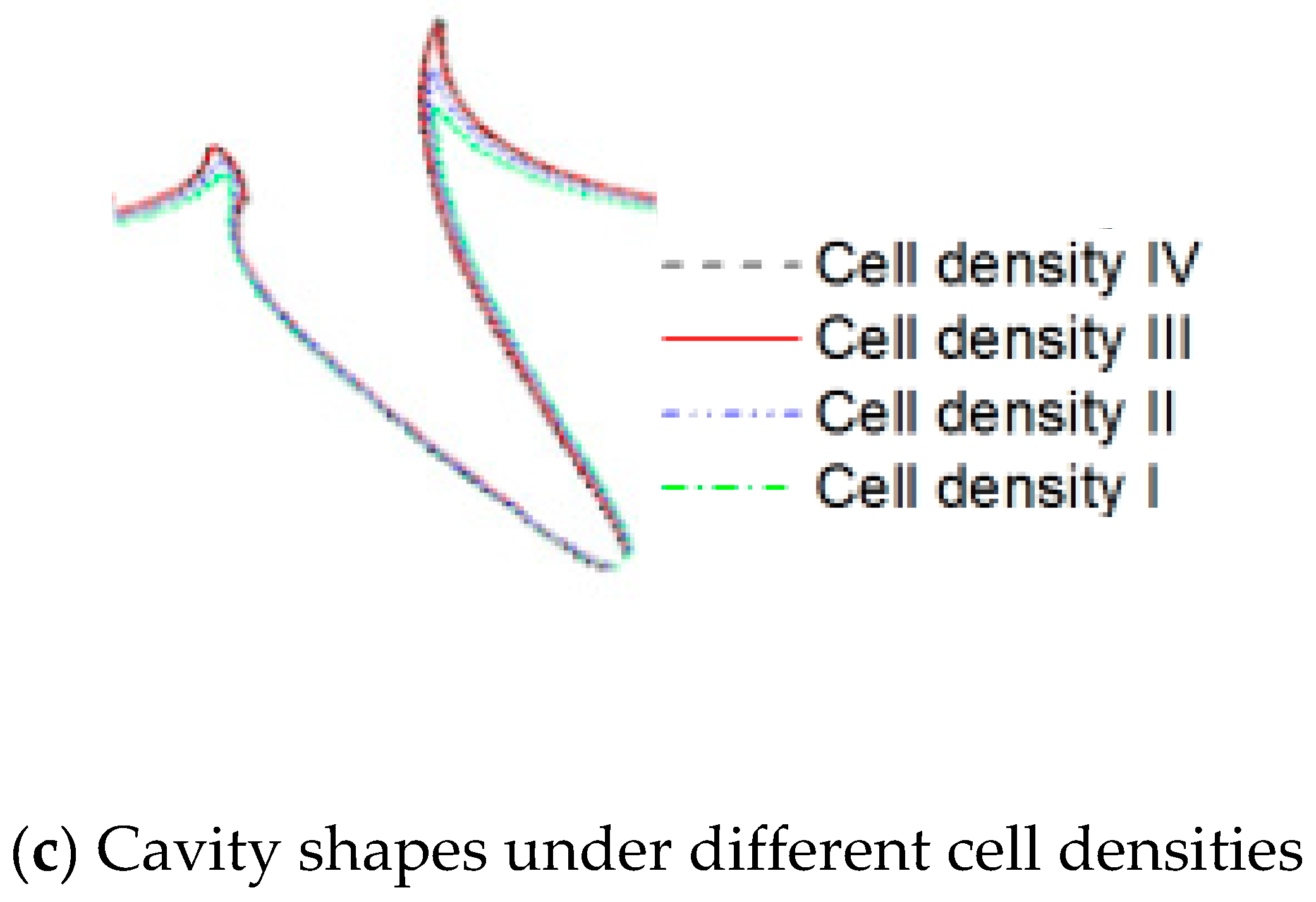
An unstructured grid consisting of 383,800 cells is used to calculate the simulation and the local mesh near the projectile is shown in Figure 1b. Three other grids consisting of 232,500, 306,300 and 437,300 cells are also used to check the grid sensitively of the solutions. According to the number of cells, the cell density from sparse to dense is numbered as I, II, III, IV, respectively. The comparison of the cavity shape at T = 30 under different cell density conditions is shown in Figure 1c. By comparing the cavity shapes for these grids, it can be found that the cavity shapes for cell density III and IV are almost the same. Considering the calculation accuracy and cost, the cell density III will be used to carry out the following simulation.
For numerical simulation, we use the commercial CFD software Fluent [22] to solve the governing equations. The top of the computational domain is specified as pressure inlet boundary; while the sides and bottom of the domain are set to be pressure outlet boundary with the pressure equals to the local static pressure. The time-dependent governing equations are discretized by using the finite volume method, and the PISO scheme is used to solving the pressure-velocity coupling algorithms. The second order upwind scheme is used for the convection terms and the central-differenced for the diffusion term in the momentum equations. The PRESTO scheme is used for the pressure interpolation. The QUICK scheme is used for the transport equation for the volume fractions.
In this research, the minimum cell size of the grid is set about 5 × 10⁻⁶ m, the time interval (Δt) of the simulation is calculated based on the CFL condition (Courant number is less or equal to one.).

2.6. Validation of Numerical Simulations

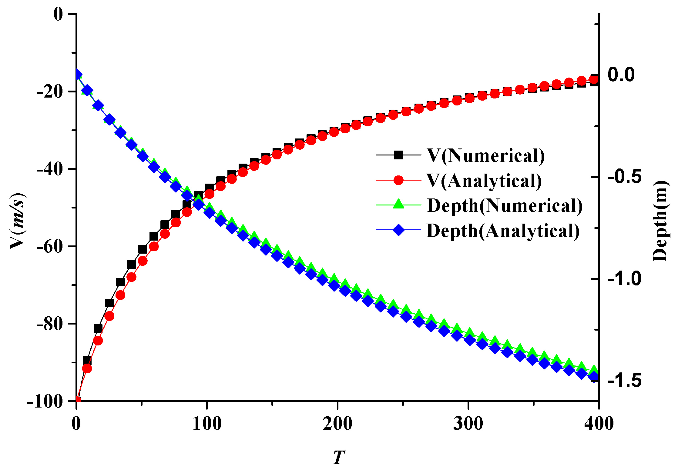
In this paper, for convenience we define non-dimensional time T = V0t/D, t is the real water entry time. The comparison of time histories of velocity and penetration depth of vertical water entry with initial velocity of 100 m/s obtained by analytical method [12] and our numerical simulation is shown in Figure 2.
From Figure 2, it can be found that the variations of both our numerical velocity and penetration depth agree well with their corresponding analytical results. However, there are still deviations between the velocity variations. This is mainly because the analytical method considers the drag coefficient as constant; however, it is actually variable and larger than the constant value of analytical method especially at the early stage of water entry, which means that the numerical velocity after entering the water is smaller than the analytical results.
Comparison of the cavity evolution of numerical and analytical results for the case 45_8D_V500 at different time T = 20, 30 and 40 are shown in Figure 3. It can be clearly seen that the results of the cavity shapes of numerical and analytical results also agree well near the projectile, but there are discrepancies near the water surface, which are due to the assumptions that the analytical methods neglecting the uplift of the water surface and the influence of atmospheric pressure and surface tension.
According to the above studies of this sub-section, the numerical simulations in this paper can be considered to be reliable [23,24], and the further numerical results will be presented as follows.

3. Results and Discussions

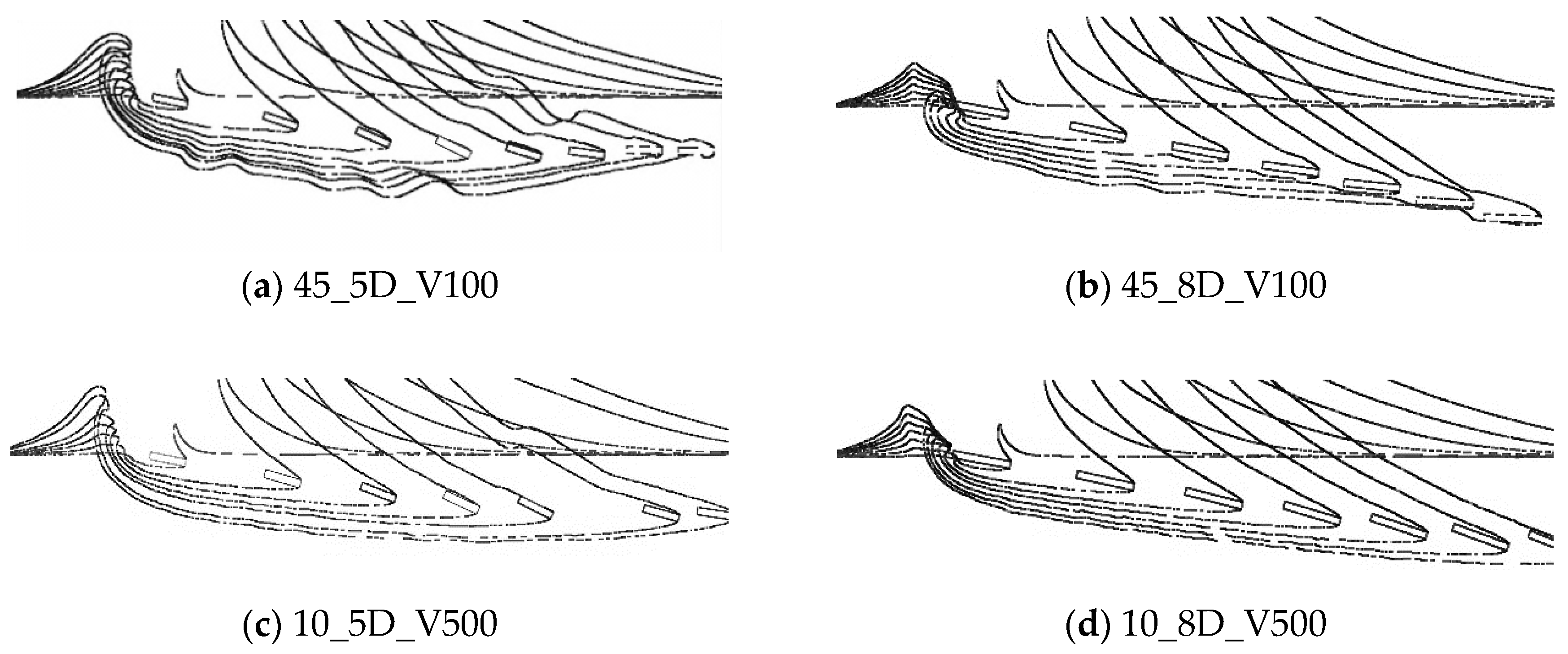
Cavity evolution of water entry for different entry angles, lengths and velocities of projectiles are shown in Figure 4 and Figure 5. The initial time T = 10, and the time interval Δ T between each cavity contour is 20. From Figure 4a, the entry angle of projectile is 10°, during the water entry process, at the early stage, the water surface is ascending quicker than the descending of cavity, and its interface appears relatively coarse, later, the projectile tends to touch and disturb the cavity surface, which in consequence interact with each other, the pitch angle of projectile changes remarkably, and the projectile will ricochet.
Comparing the Figure 4a with Figure 4b, the projectile with the large length (8D) has better stability, and the variation of its pitch angle is decreased, even though it still vibrates.
With the increase of its entry velocity (Figure 4c,d), the cavity wall during the whole water entering process keeps relatively smoother even the projectile still plans on the cavity surface; however, the shorter length projectile still has the tendency to ricochet (Figure 4c), while the long projectile moves stable along its entry angle.
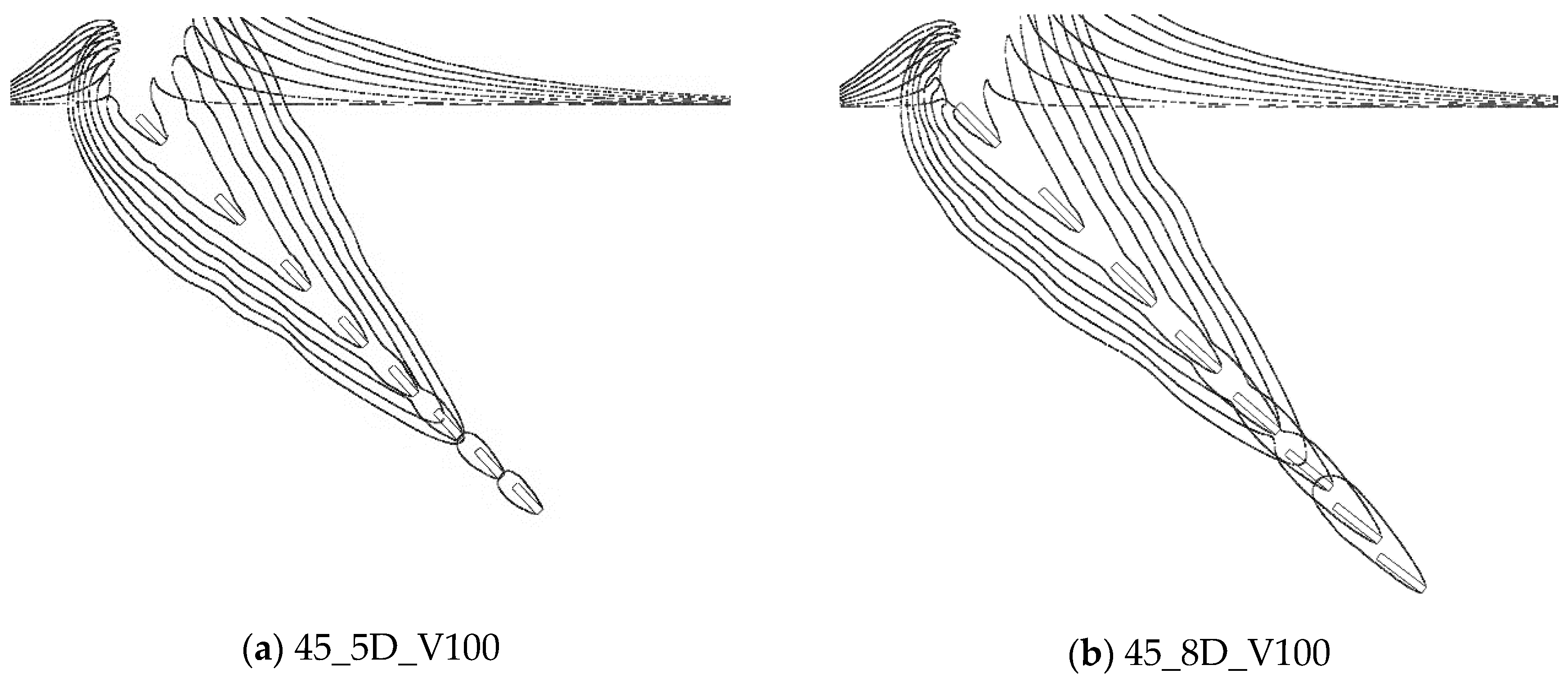
With the increase of its entry angle to 45°, the projectile moves more stable after the entry. The deep seal of cavity appears for low speed projectile (Figure 5a,b), and the time of deep seal for short projectile (L/D = 5) is almost the same with the long one (L/D = 8). With the increase of velocity (Figure 5c,d), the appearance of deep seal is delayed. Meanwhile, smoothness of cavity surface can be maintained for longer. On the other hand, for a long projectile, its distance to the entry point is larger than that of the short one at the same time period, which shows that the decrease of velocity gradient of 8D projectile is smaller than that of projectile with short length (Figure 5D).
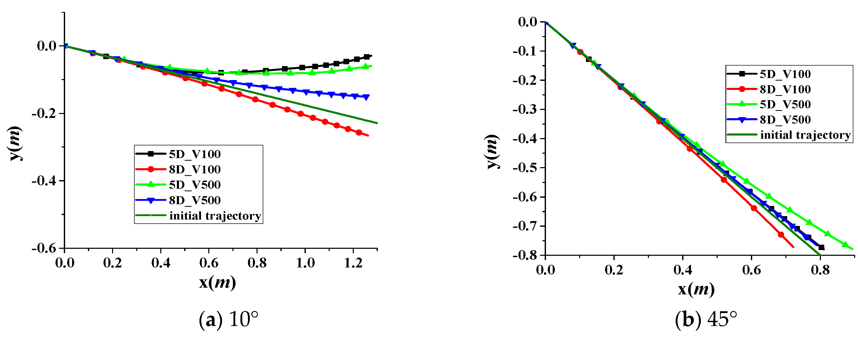
Figure 6 shows the trajectories of water entry at different conditions. From Figure 6a, it is clear that, when the entry angle is small (10°), the projectile with L/D = 5 ricochets for both the entry velocity of 100 and 500 m/s, and with L/D = 8, even there is no appearance of ricochet, its deviation from the initial trajectory which is the line along the initial water entry angle is still large. With the increase of entry angle (Figure 6b,c), the trajectory deviations become small for both projectiles; therefore, the projectile length does not have much effect on its trajectory deviation at large entry angles.
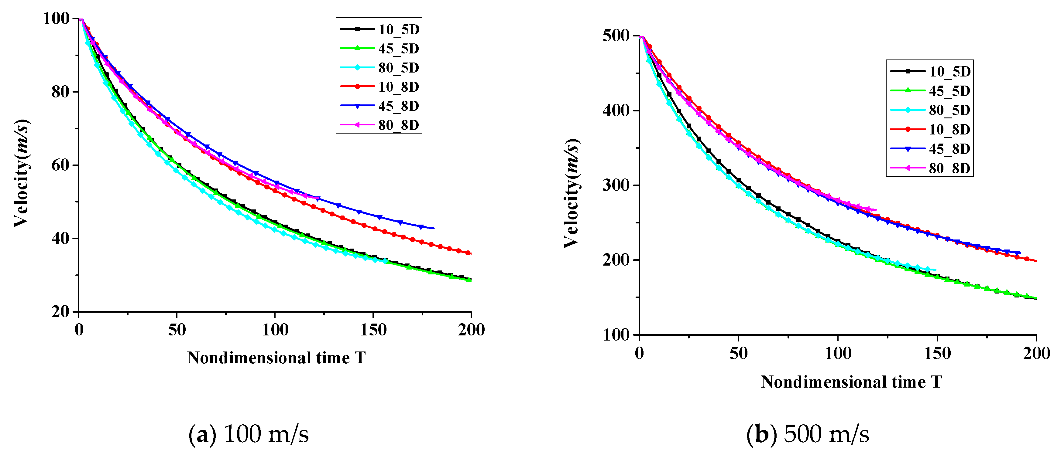
Figure 7 shows the time histories of velocity magnitude during the water entry process. It is clear that the velocity decay with L = 5D is faster than that of L = 8D, the velocity variations caused by the entry angles are small compared with that by its length modification.
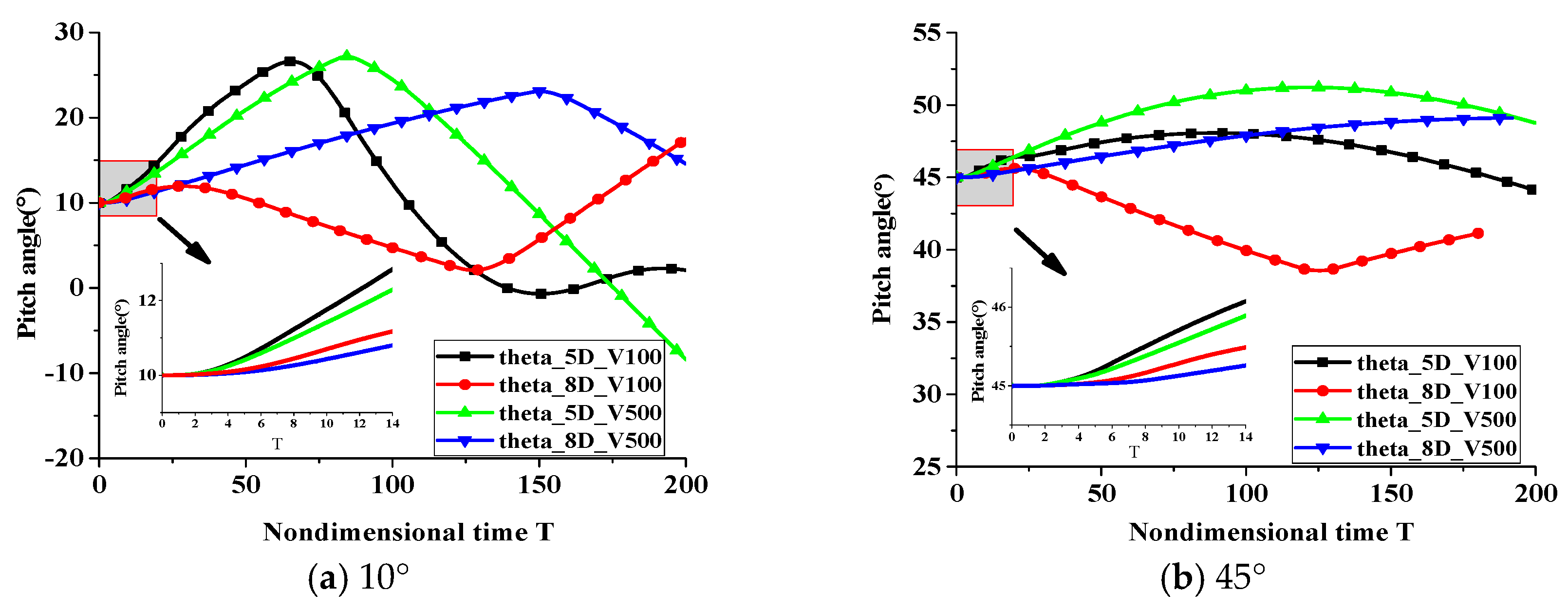
The pitch angle of projectile vibrates during the water entry process. At the initial stage of oblique water entry, the contact area at the head is asymmetric, the bottom side of the projectile head touches the water first, which generates the pitch moment and increases the pitch angle, then the attitude of projectile modifies, till its tail impacts the cavity surface and generates the opposite pitch moment, which make the pitch angle decrease and vibrate periodically.
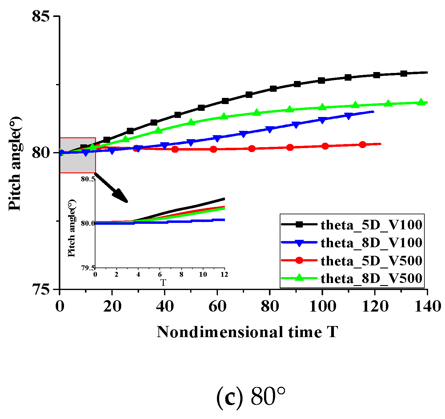
The variations of pitch angle at different entry conditions are shown in Figure 8. It is clear that, as the initial entry angles increase, the fluctuation amplitude of pitch angles decrease, and their vibrating periods become longer. When the entry angle is 10° (Figure 8a), the pitch angle grows quickly for short length projectile L = 5D, it touches the upper cavity wall earlier, and make the time taken for pitch angle begin to decrease, and its vibration period is shorter than that of projectile with L = 8D. With the increase of entry angles (Figure 8b for 45°, Figure 8c for 80°), the variations of pitch angles become small.
Zoom-in view of the initial entry stage in Figure 8a–c, it is clear that, compared with the short projectile (4D), the long projectile (8D) has small initial pitch angle and better stability.
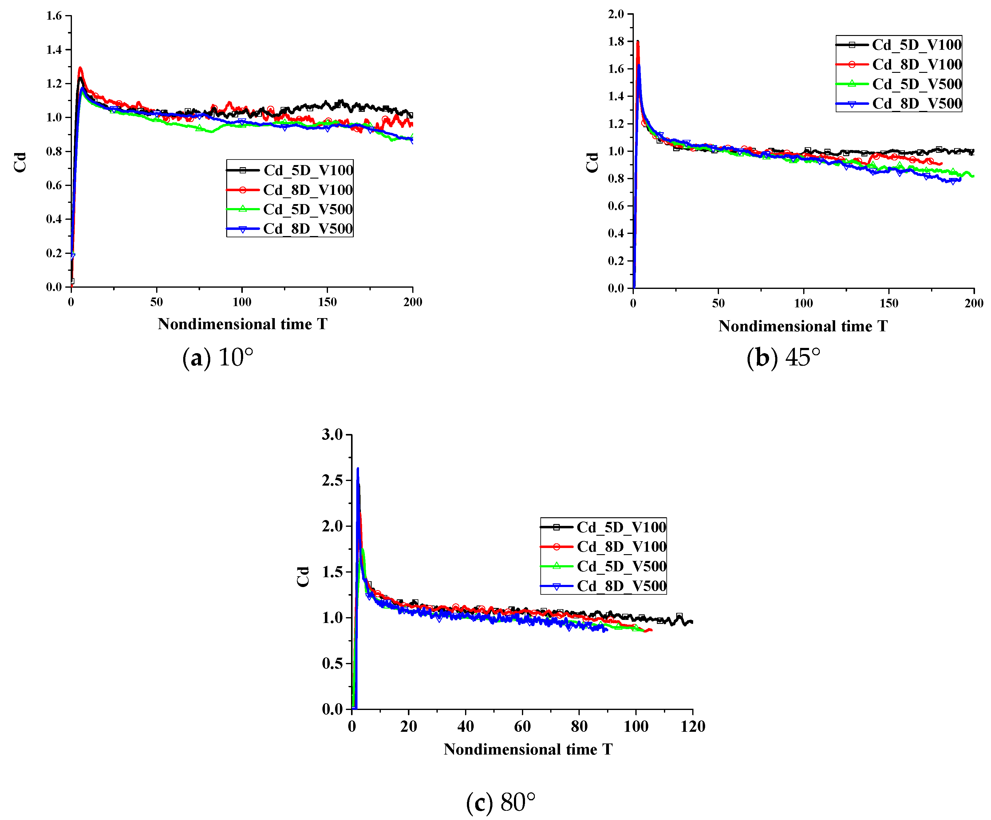
The time histories of drag coefficients during the water entry process are given in Figure 9. The drag coefficient is defined as Cd = 2F/ρV2A, where F stands for the drag force, ρ means the density of the water, and A denotes the characteristic area. It is clear that the initial impact causes very high drag and it grows quickly with the increase of entry angle and velocity.
After the initial impact, the drag coefficients tend to decrease slowly for all cases and the value is almost constant. It can be concluded that, after the projectile entering into water, its drag is only related to its hydrodynamic shape, the influence of entry velocity and angle on the drag coefficient is not obvious.

4. Conclusions

Water entry is an interesting and complex topic in fluid dynamics for more than a century, and until now most investigations about water entry mainly focus on the vertical cases, while oblique water entry, especially for high velocity cases, have not been investigated widely. Compared to the process of the vertical water entry, the evolution and stability of the oblique cavity and the projectile trajectory are more difficult to predict.
In this paper, the oblique water entry of projectiles with different lengths, entry angles and velocities were numerically simulated based on solving coupled Navier–Stokes equations and ballistic equations. The numerical results agree well with available analytical results for the cavity shape near the projectiles. The influences of initial water entry velocity, entry angle and projectile length on the cavity shape, projectile trajectory and stability were discussed.
For small water entry angles, the projectile touches the cavity wall and makes the cavity wall less smooth, and a projectile with small length (5D) will ricochet. With the increase of water entry angle, the projectile becomes stable. Under the same entry conditions, the projectile with the large length (8D) has better stability and its decrease of velocity gradient is smaller.
The pitch angle of projectile vibrates during water entry, the amplitude decreases with the increase of projectile length and entry angle, and the contrary is the case for the vibration period. Furthermore, the initial impact of entering water generates very high drag and it grows quickly with the increase of entry angle and velocity.
Our results provided a better understanding of the process of the oblique water entry which can be essential for the design of air-to-sea projectiles.

Author Contributions

J.G. ran the numerical simulations, Z.C. designed the study and formulated the models, X.L. provided the information and references, and J.G., Z.C. and W.-T.W. prepared the manuscript.

Funding

Current work is supported by “the Key Laboratory Fund”, No. 61426040303162604004 and No. 614260403041803 and “the Fundamental Research Funds for the Central Universities”, No. 30917012101.

Conflicts of Interest

The authors declare no conflicts of interest.

References

  1. Lee, M.; Longoria, R.G.; Wilson, D.E. Cavity dynamics in high-speed water entry. Phys. Fluids 1997, 9, 540–550. [Google Scholar]
  2. Lee, M. Water-entry induced cavity pressure. KSME Int. J. 2000, 14, 562–568. [Google Scholar] [CrossRef]
  3. Wei, Z.-H.; Wang, S.-S.; Ma, F.; Lü, Q.-Z.; Zhong, X. Experimental Investigation of Water-Entry Phenomenon. J. Beijing Inst. Technol. 2010, 19, 127–131. [Google Scholar]
  4. Yan, H.; Liu, Y.; Kominiarczuk, J.; Yue, D.K.P. Cavity dynamics in water entry at low Froude numbers. J. Fluid Mech. 2009, 641, 441–461. [Google Scholar] [CrossRef]
  5. Yao, E.; Wang, H.; Pan, L.; Wang, X.; Woding, R. Vertical water-entry of bullet-shaped projectiles. J. Appl. Math. Phys. 2014, 2, 323. [Google Scholar] [CrossRef]
  6. Duclaux, V.; Caillé, F.; Duez, C.; Ybert, C.; Bocquet, L.; Clanet, C. Dynamics of transient cavities. J. Fluid Mech. 2007, 591, 1–19. [Google Scholar]
  7. Bergmann, R.; Van Der Meer, D.; Gekle, S.; Van Der Bos, A.; Lohse, D. Controlled impact of a disk on a water surface: Cavity dynamics. J. Fluid Mech. 2009, 633, 381–409. [Google Scholar] [CrossRef]
  8. Gao, J.; Chen, Z.; Ma, J. Numerical Investigation of the Water Entry of Two Head Shapes Bullet. In Proceedings of the 2015 8th International Conference on Intelligent Computation Technology and Automation (ICICTA), Nanchang, China, 14–15 June 2015; pp. 584–587. [Google Scholar]
  9. Truscott, T.T.; Epps, B.P.; Belden, J. Water entry of projectiles. Annu. Rev. Fluid Mech. 2014, 46, 355–378. [Google Scholar] [CrossRef]
  10. Aristoff, J.M.; Bush, J.W.M. Water entry of small hydrophobic spheres. J. Fluid Mech. 2009, 619, 45–78. [Google Scholar]
  11. Aristoff, J.M.; Truscott, T.T.; Techet, A.H.; Bush, J.W.M. The water entry of decelerating spheres. Phys. Fluids 2010, 22, 32102. [Google Scholar] [CrossRef]
  12. Guo, Z.; Zhang, W.; Xiao, X.; Wei, G.; Ren, P. An investigation into horizontal water entry behaviors of projectiles with different nose shapes. Int. J. Impact Eng. 2012, 49, 43–60. [Google Scholar] [CrossRef]
  13. Guo, Z.; Zhang, W.; Cong, W. Experimental and theoretical study on the high-speed horizontal water entry behaviors of cylindrical projectiles. J. Hydrodyn. Ser. B 2012, 24, 217–225. [Google Scholar] [CrossRef]
  14. Shi, H.-H.; Itoh, M.; Takami, T. Optical observation of the supercavitation induced by high-speed water entry. J. Fluids Eng. 2000, 122, 806–810. [Google Scholar] [CrossRef]
  15. Truscott, T.T.; Techet, A.H. Water entry of spinning spheres. J. Fluid Mech. 2009, 625, 135–165. [Google Scholar] [CrossRef]
  16. Zwart, P.J.; Gerber, A.G.; Belamri, T. A two-phase flow model for predicting cavitation dynamics. In Proceedings of the Fifth International Conference on Multiphase Flow, Yokohama, Japan, 30 May–4 June 2004; Volume 152. [Google Scholar]
  17. Zwart, P.J. Numerical Modelling of Free Surface and Cavitating Flows. In VKI Lucture Series; Ansys Canada Ltd.: Waterloo, ON, Canada, 2005; pp. 1–25. [Google Scholar]
  18. Yu, A.; Tang, Q.; Zhou, D. Cavitation Evolution around a NACA0015 Hydrofoil with Different Cavitation Models Based on Level Set Method. Appl. Sci. 2019, 9, 758. [Google Scholar] [CrossRef]
  19. Launder, B.E.; Spalding, D.B. Lectures in Mathematical Models of Turbulence; Academic Press: London, UK, 1972. [Google Scholar]
  20. Kunz, R.F.; Lindau, J.W.; Gibeling, H.J.; Mulherin, J.M.; Bieryla, D.J.; Reese, E.A. Unsteady, three-dimensional multiphase cfd analysis of maneuvering high speed supercavitating vehicles. AIAA 2003-841. In Proceedings of the 41st Aerospace Sciences Meeting and Exhibit, Reno, NV, USA, 6–9 January 2003. [Google Scholar]
  21. Savchenko, Y.N.; Vlasenko, Y.D.; Semenenko, V.N. Experimental studies of high-speed cavitated flows. Int. J. Fluid Mech. Res. 1999, 26, 365–374. [Google Scholar] [CrossRef]
  22. Fluent Inc. Fluent Theory Guide; ANSYS, Inc.: Canonsburg, PA, USA, 2014. [Google Scholar]
  23. Roache, P.J. Quantification of uncertainty in computational fluid dynamics. Annu. Rev. Fluid Mech. 1997, 29, 123–160. [Google Scholar] [CrossRef]
  24. Blocken, B.; Gualtieri, C. Ten iterative steps for model development and evaluation applied to Computational Fluid Dynamics for Environmental Fluid Mechanics. Environ. Model. Softw. 2012, 33, 1–22. [Google Scholar] [CrossRef]
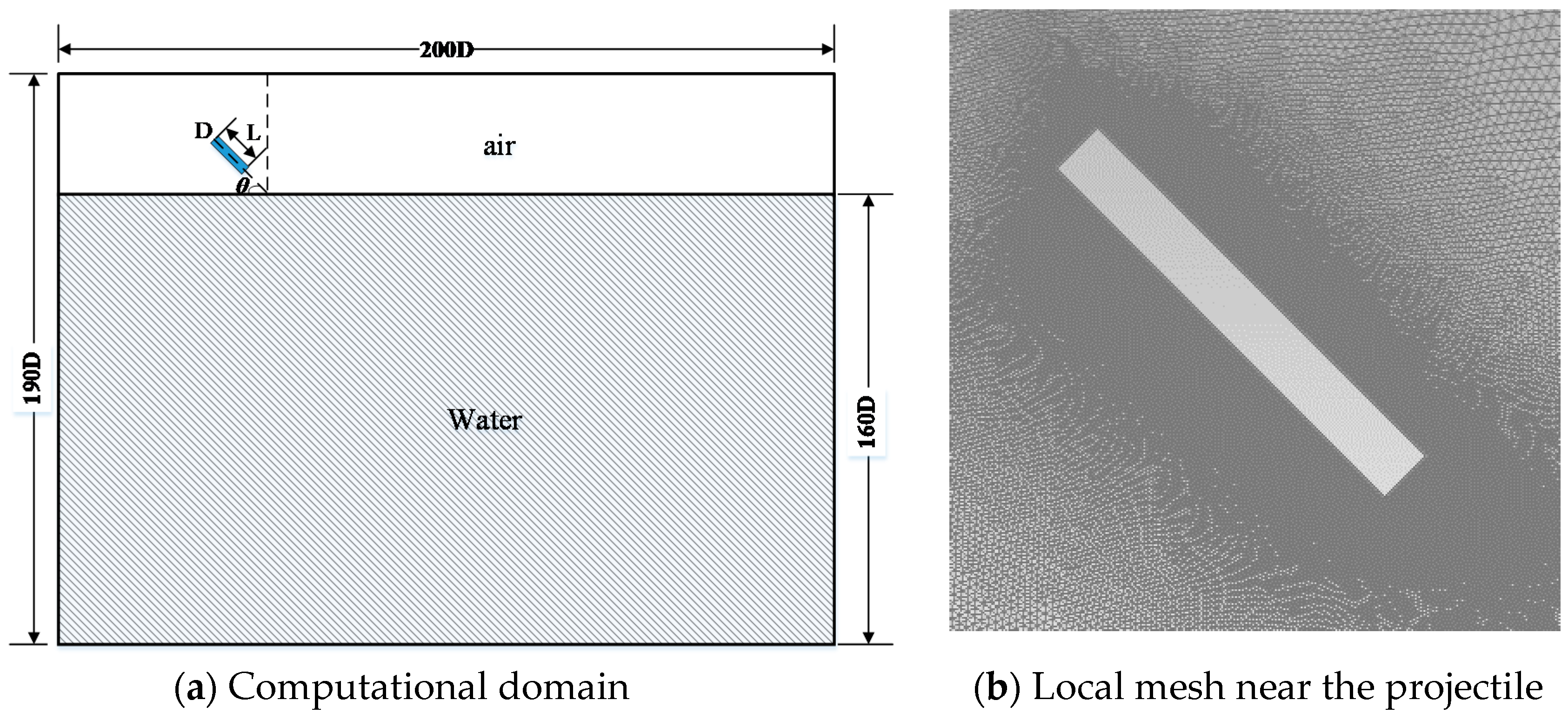
Figure 1. Problem illustration.
Applsci 09 01858 g001aApplsci 09 01858 g001b
Figure 2. Comparison of numerical and analytical results of vertical water entry.
Applsci 09 01858 g002
Figure 3. Between the cavity evolution of numerically result and predicted by the analytical cavity models.
Applsci 09 01858 g003
Figure 4. Evolution of water entry at initial angle 10°: (a) 10_5D_V100, (b) 10_8D_V100, (c) 10_5D_V500, (d) 10_8D_V500.
Applsci 09 01858 g004
Figure 5. Evolution of water entry at initial angle 45°: (a) 45_5D_V100, (b) 45_8D_V100, (c) 45_5D_V500, (d) 45_8D_V500.
Applsci 09 01858 g005aApplsci 09 01858 g005b
Figure 6. Trajectory curves of water entry for different initial inclination angles: (a) 10°, (b) 45°, (c) 80°.
Applsci 09 01858 g006aApplsci 09 01858 g006b
Figure 7. Velocity magnitude variations of water entry with initial velocity of (a) 100 m/s, (b) 500 m/s.
Applsci 09 01858 g007
Figure 8. Time histories of pitch angles at different entry angles: (a) 10°, (b) 45°, (c) 80°.
Applsci 09 01858 g008aApplsci 09 01858 g008b
Figure 9. Drag coefficients of water entry for different initial inclination angles: (a) 10°, (b) 45°, (c) 80°.
Applsci 09 01858 g009