Article

Design and Analysis of Pneumatic Downforce Regulating Device for No-Till Corn Planter

1
College of Engineering, China Agricultural University, Beijing 100083, China
2
Cultivated Land Conservation Agricultural Science Observation and Experiment Station, Northern Hebei Province, Ministry of Agriculture and Rural Affairs, Beijing 100083, China
3
Beijing Vocational College of Agriculture, Beijing 100083, China
*
Author to whom correspondence should be addressed.
Agriculture 2022, 12(10), 1513; https://doi.org/10.3390/agriculture12101513
Submission received: 12 August 2022 / Revised: 15 September 2022 / Accepted: 16 September 2022 / Published: 21 September 2022

Abstract

:
To avoid the issues of undesired soil compaction and seeding depth variation caused by the downforce fluctuation of the corn no-till planter, the influence of the structural parameters of the air spring on the downforce was researched in this paper, by establishing the gas–solid coupling simulation model of the air spring. The downforce test bench was built to verify the simulation model; the test showed that the vertical output force error of the simulation model was 4.79%, the pitch diameter error was 0.76%, and the pressure error was 5.07%. The cord angle, piston angle and piston diameter were used as influencing factors to carry out single-factor experiments. The influences of structural parameters on downforce were analyzed from four aspects: the vertical output force, the vertical stiffness, the pressure difference and the deformation rate. The results showed that the cord angle reduced the effective area and its change rate during deformation by limiting the radial deformation of the bellow. When the cord angles were 30°, 45° and 60°, the deformation rates were 65.6%, 20.3% and 4.8%, respectively. The cord angle had a positive effect on the vertical output force when the cord angle was in the range of 30~56°, and it had a negative impact in the range of 56~60°. As the cord angle increased, the vertical stiffness decreased. As the piston angle increased, the effective area of the air spring decreased, and the change in internal pressure decreased, reducing its vertical output force and stiffness. The piston diameter had little effect on the internal pressure and deformation rate. It increased the vertical output force and stiffness by increasing the effective area. The structural parameters of the air spring had a significant impact on the stability of the downforce; the structure of the air spring should be optimized according to the downforce demand of the corn no-till planter.

1. Introduction

Downforce refers to the load the planter applies to the seeding unit, including the self-weight of the unit and the additional load applied to the unit through the profiling unit [1,2]. Compared with traditional tillage, no-tillage seeding has no plowing and rotary tillage in the seeding belt. The no-tillage surface evenness was poor, and the soil fluidity was low, which made it easy to cause fluctuations in the downforce of the seeding unit [3]. The existing research results show that when the downforce of the seeding unit is insufficient during seeding, the positive pressure of the stubble-breaking disc is not enough to cut the stubble on the no-till belt and open the furrow of a qualified depth, resulting in insufficient seeding depth. At the same time, inadequate downforce results in loose soil in the seed furrow, increasing the generation of air pockets, accelerating moisture loss in seed furrows and affecting corn germination [4,5]. Therefore, extra downforce is usually applied to the unit to ensure furrow depth stability in the corn no-till seeding process. However, the excessive downforce carried by the gauge wheel of the unit can easily cause excessive compaction of the seed furrow, destroy the soil pore structure and increase the soil bulk density of the seed furrow by about 1.6–6.1% [6,7]. Excessive downforce creates hard walls on both sides of the double-disc open seed furrow, hindering corn roots’ normal development [8]. The seeding depth increased with the increase in downforce, resulting in difficulties in seed germination and soil breaking, delaying the emergence of corn. Especially in the alpine-cold regions, excessive seeding depth directly leads to insufficient temperature accumulation and reduced seed germination rate [9]. In addition, downforce is one of the key indicators affecting seeding quality, which directly affects the qualified rate of seeding depth and spacing. In the range of 600~900 N, the variation coefficient of seeding depth decreases with the increase in downforce [10,11]. Stable downforce is an essential guarantee for achieving stable seeding depth, preventing competition for sunlight, water and nutrients, and obtaining a high emergence rate and final yield [12,13].
To improve the stability of the downforce, the existing no-till planters usually applied additional downforce to the seeding unit through a coil-spring downforce regulating device. The pre-tightening force and quantity of the coil spring were adjusted before the start of seeding to realize the pre-adjustment of the downforce, according to the soil texture, seeding depth, working speed, etc. [14]. But it could not be actively adjusted in real time while working to further improve the matching accuracy of downforce and operating conditions and realize the refined seeding management. The existing research mainly adjusted downforce in real time through two active methods: hydraulic and pneumatic. The hydraulic downforce regulating device used a hydraulic cylinder to replace the coil spring, and the seeding unit was raised or lowered to adjust the downforce through the hydraulic cylinder [15]. The pneumatic downforce regulating device (PDRD) used an air spring instead of a coil spring, adjusting the downforce through inflating and deflating to the air spring. The PDRD had a better downforce stability control effect under the condition of no-till surface undulation and an excellent vibration reduction performance. Huang et al. [16,17] developed a pneumatic downforce control system suitable for no-till planters by monitoring the downforce of the gauge wheel and selected the air spring for automobiles as the execution component, which effectively improved the stability of seeding depth and downforce. Some companies such as John Deere, Precision Planting and Kinze had also launched planters with air springs and downforce control systems to improve the quality of seeding under no-till conditions, realizing the monitoring and adjustment of the single-row downforce, which improved the stability of high-speed seeding and increased corn yield [18,19,20]. The existing research on the PDRD mainly focused on the air spring application and the control system’s development. The relationship between the air spring’s structural parameters and the seeding unit’s downforce was unclear.
As the main working part of the PDRD, the rolling lobe air spring was a kind of non-metallic spring that realized elasticity by filling the soft airtight bellows with compressed air and utilizing the compressibility of the air. Its bearing characteristics were affected by parameters such as internal gas, rubber bellows and piston shape, and determined the effect of downforce regulation on the planter. In recent years, the research on the parameter optimization of air springs in different application scenarios by the gas–solid coupling simulation methods has gradually increased, and the consistency of the simulation and physical test results have also been verified.
In this study, the Finite Element Method (FEM) was used to study the influence of the structural parameters of the air spring in the PDRD on the downforce. We have provided theoretical supports and references for optimizing the structural parameters of the air spring and improving downforce stability during no-tillage seeding.

2. Materials and Methods

2.1. F E Model

2.1.1. Model Material

The seeding unit was connected to the frame through a four-bar linkage mechanism for up and down profiling during the operation of the corn no-till planter. The upper part of the air spring was fixed to the planter frame through the upper fixing bracket, and the lower part was hinged to the four-bar linkage mechanism through the lower fixing bracket (Figure 1). The air spring was compressed or stretched under the drive of the four-bar linkage mechanism during the profiling process. The vertical output force (VOF) of the air spring determined the downforce of the frame to the unit. The air–solid coupling method in the ABAQUS F E simulation could simulate the deformation of the air and the VOF during the height change of the air spring [21,22,23].
The rolling lobe air spring selected in the PDRD was mainly composed of an upper plate, rubber bellows, piston and sealing rings (Figure 2). According to the force and deformation of the air spring, the air spring was simplified into four parts: upper plate, piston, bellows and the gas in the cavity for modeling. The upper plate and piston material were usually aluminum alloy or nylon. Its deformation rate was low and not the focus of this analysis, so it was regarded as a rigid body in the simulation, and we ignored its deformation.
The bellows was vulcanized from rubber and cord. The rubber material had strong nonlinear elasticity, and its properties were simulated by hyperelastic materials. The Mooney–Rivlin model was used to simulate rubber in ABAQUS; the material parameters are shown in Table 1 [24]. The cord was made of nylon bonded with rubber. The cord layer mainly included four parameters: the pitch of the cord layer, the pitch of the cord, the radius of the cord and the angle of the cord. In the simulation, the rebar unit was used to simulate the cord layer in the bellows, and the cord was embedded in the rubber body. The cord pitch was simulated by the spacing of the rebar element; the cord layer pitch was simulated by the distance between the neutral plane and the rebar element; the cord radius was simulated by the cross-sectional area of the rebar element; the cord angle was simulated by the rebar element angle. When the air spring was working, with the deformation of the bellows, the bellows compressed air, and the interaction between the compressed air and the bellows was a typical fluid-structure coupling phenomenon [25]. The cavity model in ABAQUS provided the coupled analysis used to simulate the gas in the cavity.

2.1.2. Contact and Boundary

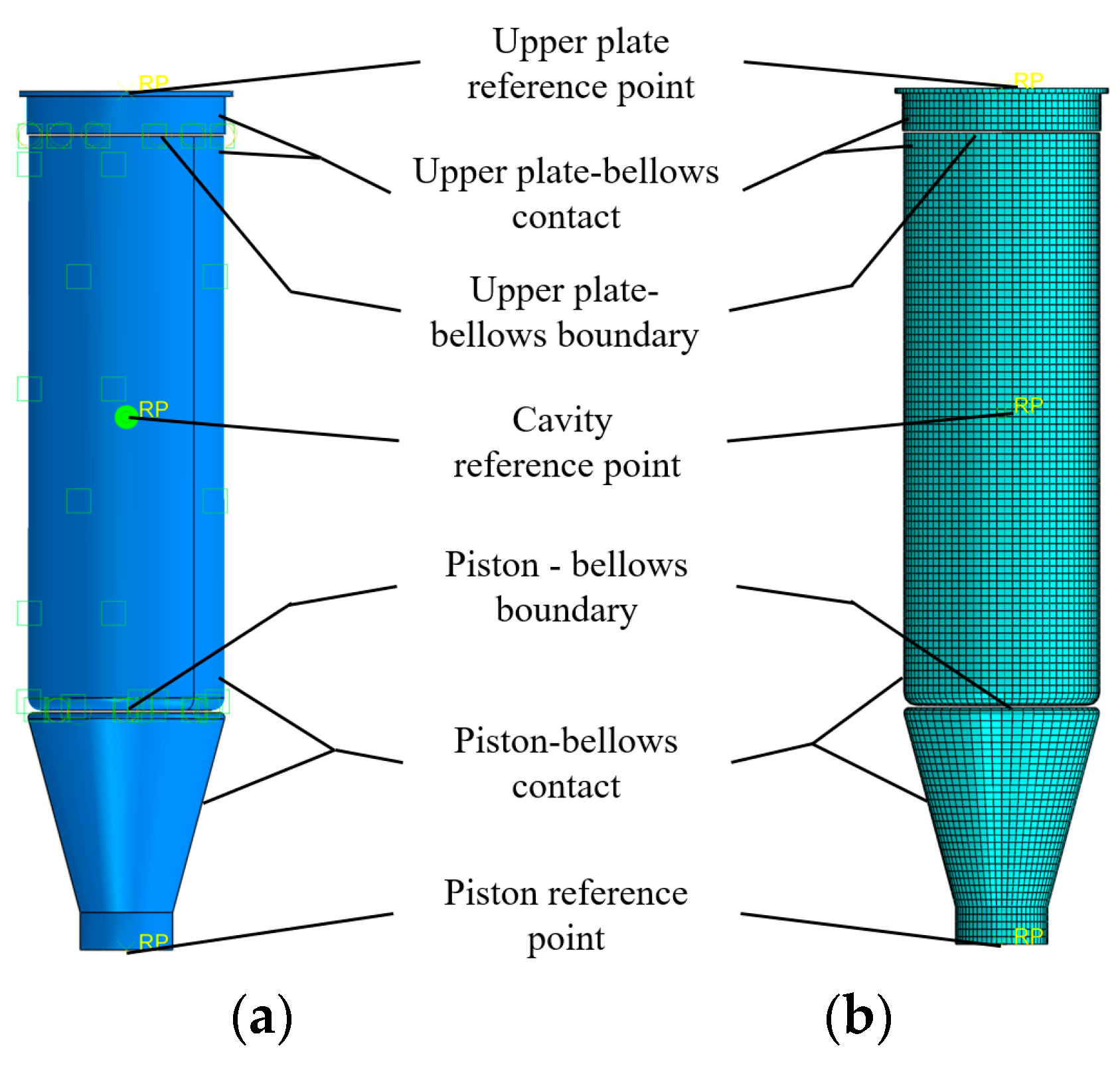
In the PDRD, the upper plate of the air spring was fixed to the planter frame through the upper fixing bracket, and the piston was hinged with four-bar linkage through the lower fixing bracket piston rotated around the seeding unit connection plate (Figure 1). In the F E simulation, the undulations during the seeding were simulated by the translation of the piston; the upper plate was fixed by the degree of freedom (DOF) constraints of the reference point. The nodes of the fluid element of the bellows were fixed with the repeated nodes of the upper cover plate and the piston based on the TIE tool. The contact between the bellows, the upper plate and the piston’s side was defined as non-slip contact. An airtight cavity was formed through the two sides of the bellows, the upper and lower faces of the plate and piston, and the cavity was filled with air.

2.1.3. Meshing and Step Definition

When establishing the F E model of the downforce regulating air spring, the bellows was simplified as a shell element, and the S4R element simulated the shell element. The shell thickness was the same as that of the bellows, and the mesh was generated by sweeping. By referring to the existing research and previous pre-experiments, on the basis of ensuring the speed and accuracy of the simulation test, the mesh size is selected as 3 mm. The upper plate and piston of the air spring were shelled, and the discrete rigid shell elements of the upper plate and the piston were simulated by the S4R element. The mesh is generated by sweeping; the mesh size is the same as that of the bellows, which is 3 mm.
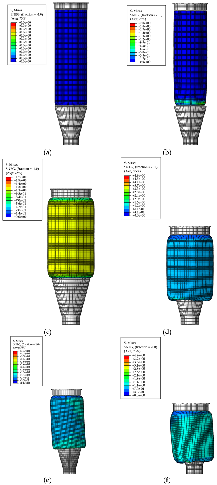
The existing research shows that when the no-till seeding speed is 4–10 km/h, the vibration of the gauge wheel and the seeding unit of the seeder is mainly low-frequency (≤1 Hz) vibration [26]. The dynamic and static stiffness of the air spring under low-frequency vibration were the same [27], so the static output force and stiffness were used in this paper to replace the dynamic characteristics under field conditions. The analysis process of the PDRD were mainly divided into four steps. The first step was the inflation process, constraining the upper plate and piston’s DOF so that the air spring was in a state of maximum elongation (Figure 3a), and the fluid cavity in the bellows was inflated to 0.3 MPa (Figure 3b). The second step was the compression process, keeping the pressure of the fluid cavity at 0.3 MPa, constraining the DOF of the piston. The upper plate moved down 145 mm (Figure 3c), compressing the height of the air spring to 200 mm (Figure 3d), when the four-bar linkage mechanism was in a horizontal position. The third step was to constrain the DOF of the upper plate, disconnecting the air source of the fluid cavity, and the internal pressure of the fluid cavity changed with the volume of the fluid cavity. The piston moved down 40 mm and sideways 8 mm to the lowest position of the piston (Figure 3e), when the air spring was in the maximum stretch state. In the fourth step, the constraints were kept the same as in the third step. The piston-derived bellows moved up 80 mm to the highest position (Figure 3f). At this time, the air spring was compressed to the lowest height, the internal volume of the bellows was the smallest and the internal air pressure was at its maximum.

2.2. Test Design and Index Measurement

The PDRD used an air spring instead of coil spring, and its design goal was to improve the downforce stability of the seeding unit. During the working process of the PDRD, the additional downforce exerted on the seeding unit was determined by the VOF of the air spring. The influence of the structural parameters of the air spring on the downforce was studied by the single-factor F E simulation test.

2.2.1. Test Factors

During the expansion and deformation of the air spring, the bellows was elastically deformed along the outer surface of the piston under the action of the internal air, as shown in Figure 4. Its bearing capacity was mainly affected by the internal air pressure and effective area of the air spring, and the calculation equation was as follows:
F k = p A e A e = π R R 2 2
where Fk is the vertical load of the air spring, N; p is the internal air pressure of the air spring, MPa; Ae is the effective area of the air spring, m2; R is the inner radius of bellows, m; R2 is the radius of roll ear, m.
The maximum downforce required by the corn no-till planter is about 2500 N [17,28]; excluding the self-weight of the seeding unit of 1500 N, the maximum additional downforce provided by the PDRD is 1000 N. The action point of the air spring at the four-link is one-third of the length of the link, and the maximum vertical output force of the air spring is determined to be 3000 N. The maximum profiling height of the corn no-till planter unit is 240 mm, and the maximum profiling height of the air spring is determined to be 80 mm according to the installation size. To prevent the bellows from being involved in the piston and the cover plate, the minimum air pressure shall be higher than 0.05 MPa [29]. The greater the internal air pressure of the air spring, the greater its vertical stiffness (VS) [28]. To reduce the vs. of the air spring and the downforce fluctuation, the air pressure range inside the air spring was determined to be 0.05~0.6 MPa.
The cord angle is the angle between the inner cord and the meridian of the bellows (Figure 4b); it affects the deformation rate of the rubber in different directions, and the cords are arranged vertically between adjacent layers. To ensure the lateral and vertical stability of the air springs, the angle of the cord was usually between 30°~60° [30], and the cord angles selected in the test were 30°, 45° and 60°, respectively. Compared to conical, cylindrical and curved pistons, the turbination piston helped reduce the air spring’s vs. and improve the downforce stability [31]. The turbination piston was selected, and to ensure the strength of the piston, the piston angle was selected as 5°, 10° and 15°. It could be seen from Equation (1) that the piston diameter affected the effective area of the air spring, which in turn determined the VOF of the air spring under the same air pressure. Combined with the downforce requirement of the seeding unit and the working pressure of the air spring, the piston diameters were selected as 65 mm, 75 mm and 85 mm through calculation. In summary, through consulting the manufacturers and processors, the other structural parameters of the air spring were determined: the thickness of the bellows δ is 2.5 mm, the cord spacing D0 is 1 mm, the number of cord layers is 2, the cord layer spacing D1 is 1 mm, the cord radius R3 is 0.25 mm and the working height is 200 mm. The single-factor method was used to test the influence of the experimental factors; nine simulation tests were performed in this study; the setting of the parameters is listed in Table 2.

2.2.2. Data Collection and Processing

1.
The Average VOF
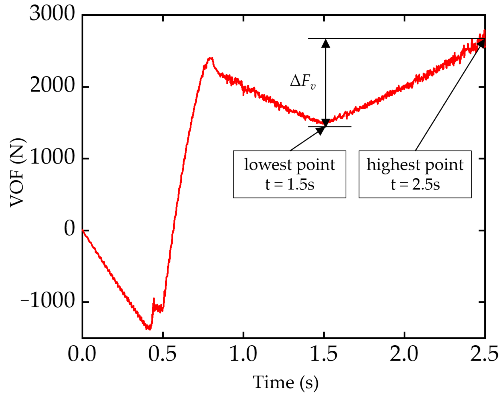
The VOF of the air spring during the deformation process determined the downforce of the unit. The appropriate VOF was selected according to the requirements of the seeding unit. In the simulation test, the piston’s vertical displacement and the upper plate’s vertical force during the deformation process were recorded through the “File output manager” function of the step module in ABAQUS. The average VOF of the air spring in the simulation test was calculated by Equation (2):
F M v = t = 1.5 t = 2.5 F v n
where FMv is the average VOF of the air spring, N; Fv is the VOF of the air spring at different times, N; n is the number of sampling points.
The VOF of the air spring in the simulation test is shown in Figure 5. The air spring started to inflate at 0 s, the air inside the bellows expanded, the piston was pulled upward by the bellows and the VOF < 0 at this time. During 0.5~1 s, the upper plate moved down, the air inside the bellows was compressed and the piston changed from tension to compression, when t = 1 s, VOF > 0. During 1~1.5 s, the upper plate of the air spring was fixed, the piston drove the bellows to twist downward, the internal volume of the air spring increased and the air pressure decreased, resulting in the decrease in the VOF. During 1.5~2.5 s, the piston twisted upward from the lowest to the highest position. During the upward movement, the internal volume of the air spring decreased, and the air pressure gradually increased, increasing the VOF. During 1.5~2.5 s, the VOF determined the magnitude of the downforce applied to the seeding unit during the ups and downs of the four-link. Therefore, the average VOF FMv at this stage was analyzed.
2.
The VS
The vs. of the air spring under different structural parameters determined the downforce fluctuation of the seeding unit under the same surface undulation, and then determined the downforce stability. The vs. was calculated according to Equation (3):
k s = F t = 2.5 F t = 1.5 Δ y
where ks is the VS, N/mm; Ft = 1.5, Ft = 2.5 are the VOF at different times, N; Δy is the vertical height change, mm.
3.
Deformation Rate of Bellows
The deformation rate of the bellows reflected the diameter change of the air spring before inflation and after reaching the maximum pressure. It was obtained by the difference in the maximum pitch diameter before and after deformation and calculated according to Equation (4):
k D = D d D u D u
where kD is the deformation rate of bellows, %; Dd is the pitch diameter of bellows when the internal pressure is at its maximum (t = 2.5 s), mm; Du is the pitch diameter of bellows before inflating (t = 0 s), mm.
4.
The Internal Pressure Difference
The pressure difference inside the bellows reflected the air compression state inside the air spring during the deformation process. It was obtained by the difference between the air pressure in the maximum tension (t = 1.5 s) and compression (t = 2.5 s) state, and the pressure difference was calculated according to Equation (5):
Δ p = p c p t
where Δp is the internal pressure difference, MPa; pc is the air pressure in the maximum compression state (t = 2.5 s), MPa; pt is the air pressure in the maximum tension state (t = 1.5 s), MPa.
The internal air pressure inside the bellows in the simulation test is shown in Figure 6. During 0~1 s, the internal pressure was manually set and did not change with the volume of the bellows; 1.0~1.5 s, the air spring stretched, and the internal volume of the bellows increased, resulting in the decrease in air pressure; 1.5~2.5 s, the air spring was compressed, the volume decreased, resulting in the increase in air pressure. In 1.5~2.5 s, the air spring was compressed from the maximum extension state to the maximum compression state, so the maximum pressure difference during the deformation process of the air spring at this stage was counted.

3. Results and Discussion

3.1. Experimental Verification of F E Model

To verify the accuracy of the F E simulation of the air spring, a downforce test bench for the no-till planter seeding unit was built, as shown in Figure 7. The test bench was built based on the unit of Jilin Kangda 2BMZF no-till planter. The planter adopted four-linkage for unit profiling and used four coil springs to exert additional downforce. The PDRD was installed on the four-bar linkage mechanism of the planter and used an air spring instead of coil springs to provide additional downforce. The air spring cord angle used in the test is 45°, the piston angle is 10° and the piston diameter is 75 mm. The downforce of the seeding unit was recorded by the cantilever beam pressure sensor (Dayang, Bengbu, China) on the test bench. The height change of the seeding unit was recorded by a displacement sensor (Milai, Taizhou, China), and then the vertical displacement of the piston was calculated. The air pressure changes inside the air spring were recorded by an air pressure sensor (Siemens, Munich, Germany). All the data were collected and recorded by NI-6002 data acquisition card (National Instruments, Austin, TX, USA), and the sampling frequency was 50 Hz.
The pressure inside the air spring was adjusted to 0.3 MPa by an electric proportional valve (SMC, Beijing, China) before the test, then used the lifting platform to adjust the height of the air spring at the initial position to be the same as that in the simulation and disconnected the external air supply of the air spring. The lifting platform was used to adjust the heights of the air springs to 160 mm, 180 mm, 200 mm, 220 mm and 240 mm, respectively, and recorded the VOF, pith diameter and pressure of the air spring on the PDRD at different heights. The difference between the measured and the simulated value are shown in Table 3. The results show that the maximum error of the VOF between the simulation test and the bench test is 8.18%, and the average error is 4.79%; the maximum error of the pitch diameter is 1.34%, and the average error is 0.76%; the maximum error of pressure is 7.47%, and the average error is 5.07%. The differences are relatively low; therefore, the FEA model is considered acceptable.

3.2. Impact Analysis of Experimental Factors

Table 4 shows the simulation test results of the VOF, VS, deformation rate and pressure difference of the air spring under different structural parameters. The influence of the cord angle, piston angle and piston diameter on the VOF and vs. were determined by significance analysis and the quadratic polynomial fitting method.

3.2.1. Impact Analysis of the VOF

The comparison of the air spring VOF in the torsional deformation within 1.0–2.5 s is shown in Figure 8. The VOF in 1.5~2.5 s determined the downforce of PDRD applied to the seeding unit.
Figure 8a shows the VOF under different cord angles; it could be seen that the VOF decreased with the increase in the cord angle within the selected test range. The quadratic polynomial fitting results of the VOF under different cord angles are shown as black curves in Figure 9a. When the cord angle increased from 30° to 56°, the VOF decreased with the increase in the cord angle, and when the cord angle increased from 56° to 60°, it increased with the increase in the cord angle. The rise in the cord angle reduced the deformation rate of the bellows, the deformation rates are 62.3%, 19.2% and 3.3% at cord angles of 30°, 45° and 60°, respectively, as shown in Figure 10. The reason was that the cord angle limited the deformation rate of the bellows after inflation, which affected the effective area and area change rate of the air spring after inflation. As the cord angle increased, the radial elongation of the bellows was limited, the effective radius of the air spring decreased, and the effective area decreased accordingly. Although the increase in the cord angle increased the internal pressure to a certain extent (Figure 11a), it was not enough to offset the decrease in the effective area, which eventually led to a significant reduction in the VOF. When the cord angle was 60°, the deformation rate of the bellows after inflation was too low, causing the piston to contact the inner wall of the bellows during the torsion process (Figure 10c), resulting in the fluctuations in the VOF (Figure 8a).
The test results under different piston angles can be seen in Figure 8b. With the increase in the piston cone angle, the VOF of the air spring decreased. The quadratic polynomial fitting results of the VOF under different cord angles are shown as black curves in Figure 9b. As the cord angle of the piston increased, the effective radius of the air spring decreased, the smaller the change in the internal volume of the bellows, and the smaller the increase in air pressure due to compression (Figure 10b). The reduction of the air pressure and effective radius led to the decrease in the VOF of the air spring.
The test results under different piston diameters can be seen in Figure 8c. With the increase in the piston diameter, the VOF of the air spring increased, and the VOF was approximately proportional to the square of the increasing proportion of piston diameter. The quadratic polynomial fitting results of the VOF under different piston diameters are shown as black curves in Figure 9c. The piston diameter mainly increased the VOF by increasing the effective area, and the air pressure difference varies a little under different piston diameters (Figure 10c).

3.2.2. Impact Analysis of the VS

Table 4 and Figure 8a show the vs. under different cord angles. The vs. decreased with the increase in the cord angle in the selected test range. The quadratic polynomial fitting results of the vs. under different cord angles are shown as red curves in Figure 9a. The influence of the cord angle from 45 to 60° on the vs. was 64.6% lower than that of 30 to 45°. The reason was that the cord angle limited the radial elongation of the bellows after inflation, which affected the effective area change rate during the compression process of the air spring, which affected the vs. in turn.
Table 4 and Figure 8b show the vs. under different piston angles; the vs. decreased with the increase in the piston angle in the selected test range. The quadratic polynomial fitting results of the vs. under different piston angles are shown as red curves in Figure 9b. The piston angle reduced the vs. by reducing the effective area and reducing the internal air pressure difference of the air spring. The results show that the deformation rate of the bellows under different piston angles and the VOF in the initial compression state (t = 1.5) were similar, and the vs. was mainly affected by the effective area change rate and the internal air pressure (Figure 11b).
Table 4 and Figure 8c show the vs. under different piston diameters; the vs. increased with the increase in the piston diameter in the selected range. The quadratic polynomial fitting results of the vs. under different piston diameters are shown as red curves in Figure 9c. The reason was that the pressure difference changed little under different piston diameters (Figure 10c), and the increase in the vs. was mainly caused by the rise in the effective area.

4. Conclusions

In this study, an F E simulation model of the air spring on the PDRD was established, and the torsional deformation of the air spring during the operation of the corn no-till planter was simulated and verified by a test bench. The influences of cord angle, piston angle and piston diameter on vertical output force, vertical stiffness, pressure difference and deformation rate of downforce regulated air spring were studied. The verification test shows that the differences in the F E model were acceptable; the vertical output force error of the simulation model was 4.79%, the pitch diameter error was 0.76%, and the pressure error was 5.07%.
The experimental results show that the structural parameters of the air spring had a significant influence on the downforce stability of the seeding unit, and the conclusions were as follows: the cord angle, piston angle and piston diameter had significant effects on the vertical output force and vertical stiffness of the air spring. The cord angle reduced the effective area and its change rate in the deformation process of the air spring by limiting the radial elongation of the bellows after inflation. The cord angle had a positive effect on the vertical output force when the cord angle was in the range of 30~56°, and it had a negative impact in the range of 56~60°. As the cord angle increased, the vertical stiffness decreased. As the piston angle increased, the effective area of the air spring decreased, and the change in internal pressure decreased, reducing its vertical output force and stiffness. The piston diameter had little effect on the internal pressure and deformation rate; it increased the vertical output force and stiffness by increasing the effective area. Therefore, the structure of the air spring should be optimized according to the downforce demand of corn no-till seeding.

Author Contributions

Conceptualization, X.C.; Writing—original draft preparation, X.C. and Q.W.; Writing—review and editing, D.X., S.H., X.W. and L.W. All authors have read and agreed to the published version of the manuscript.

Funding

This research was funded by the National Natural Science Foundation of China No. 52175260.

Institutional Review Board Statement

Not applicable.

Informed Consent Statement

Not applicable.

Data Availability Statement

Not applicable.

Acknowledgments

Gratitude should be expressed to all the members of the Conservation Tillage Research Centre.

Conflicts of Interest

The authors declare no conflict of interest.

References

  1. Gratton, J.; Chen, Y.; Tessier, S. Design of a spring-loaded downforce system for a no-till seed opener. Can. Agric. Eng. 2003, 45, 29–35. [Google Scholar]
  2. Virk, S.S.; Porter, W.M.; Li, C.; Rains, G.C.; Snider, J.L.; Whitaker, J.R. On-farm evaluation of planter downforce in varying soil textures within grower fields. Precis. Agric. 2021, 22, 777–799. [Google Scholar] [CrossRef]
  3. Badua, S.A.; Sharda, A.; Strasser, R.; Ciampitti, I. Ground speed and planter downforce influence on corn seed spacing and depth. Precis. Agric. 2021, 22, 1154–1170. [Google Scholar] [CrossRef]
  4. Bai, W.; Sun, Z.X.; Zhang, L.Z.; Zheng, J.M.; Feng, L.S.; Cai, Q.; Xiang, W.Y.; Feng, C.; Zhang, Z. Furrow loose and ridge compaction plough layer structure optimizing root morphology of spring corn and improving its water use efficiency. Trans. Chin. Soc. Agric. Eng. 2019, 35, 88–97. [Google Scholar] [CrossRef]
  5. Hemmat, A.; Adamchuk, V.I. Sensor systems for measuring soil compaction: Review and analysis. Comput. Electron. Agr. 2008, 63, 89–103. [Google Scholar] [CrossRef]
  6. Lipiec, J.; Horn, R.; Pietrusiewicz, J.; Siczek, A. Effects of soil compaction on root elongation and anatomy of different cereal plant species. Soil Tillage Res. 2012, 121, 74–81. [Google Scholar] [CrossRef]
  7. Abu-Hamdeh, N.H. Compaction and subsoiling effects on corn growth and soil bulk density. Soil Sci. Soc. Am. J. 2003, 67, 1213–1219. [Google Scholar] [CrossRef]
  8. Finlay, M.J.; Tisdall, J.M.; McKenzie, B.M. Effect of tillage below the seed on emergence of wheat seedlings in a hard setting soil. Soil Tillage Res. 1994, 28, 213–225. [Google Scholar] [CrossRef]
  9. Shi, D.J.; Yan, F.Y.; Fan, J.Z.; Zhong, C.S.; Lyu, J.Z. Effects of different sowing depths on seedling characters and yield of maize under no-tillage conditions. J. Hunan Agric. Univ. Nat. Sci. 2014, 2014, 19–21, 24. [Google Scholar] [CrossRef]
  10. Zhang, R. Study on Precision Depth-Control Mechanism of Corn No-Till Planter in Double-Cropping Area. Ph.D. Thesis, China Agricultural University, Beijing, China, 2016. [Google Scholar]
  11. Nielsen, S.K.; Munkholm, L.J.; Lamandé, M.; Nørremark, M.; Skou-Nielsen, N.; Edwards, G.T.C.; Green, O. Seed drill instrumentation for spatial coulter depth measurements. Comput. Electron. Agr. 2017, 141, 207–214. [Google Scholar] [CrossRef]
  12. The Keys to Consistent Emergence. Available online: https://www.precisionplanting.com/agronomy/research/the-keys-to-consistent-emergence (accessed on 20 July 2022).
  13. Liu, W.D.; Tollenaar, M.; Stewart, G.; Deen, W. Impact of planter type, planting speed, and tillage on stand uniformity and yield of corn. Agron. J. 2004, 96, 1668. [Google Scholar] [CrossRef]
  14. Virk, S.S.; Fulton, J.P.; Porter, W.M.; Pate, G.L. Row-crop planter performance to support variable-rate seeding of maize. Precis. Agric. 2020, 21, 603–619. [Google Scholar] [CrossRef]
  15. Jing, H.R.; Zhang, D.X.; Wang, Y.X.; Yang, L.; Fan, C.L.; Zhao, H.H.; Wu, H.L. Development and performance evaluation of an electro-hydraulic downforce control system for planter row unit. Comput. Electron. Agr. 2020, 172, 105073. [Google Scholar] [CrossRef]
  16. Huang, D.Y.; Zhu, L.T.; Jia, H.L.; Yu, T.T. Automatic control system of seeding depth based on piezoelectric film for no-till planter. Trans. Chin. Soc. Agric. Mach. 2015, 46, 1–8. [Google Scholar] [CrossRef]
  17. Gao, Y.Y.; Wang, X.; Yang, S.; Zhao, X.G.; Dou, H.J.; Zhao, C.J. Design and test of pneumatic downforce control system for planting. Chin. Soc. Agric. Mach. 2019, 50, 19–29. [Google Scholar] [CrossRef]
  18. John Deere 1705 Twin Row Planter. Available online: https://www.deere.com/en/planting-equipment/1705-twin-row-planter/# (accessed on 19 July 2022).
  19. Precision Planting. Available online: https://www.precisionplanting.com/products/product/airforce (accessed on 19 July 2022).
  20. Kinze. Available online: https://www.kinze.com/planter-performance/down-force/pneumatic/ (accessed on 19 July 2022).
  21. Bester, T.; Oman, S.; Nagode, M. Determining influential factors for an air spring fatigue life. Fatigue Fract. Eng. Mater. Struct. 2019, 42, 284–294. [Google Scholar] [CrossRef]
  22. Wang, H.Y.; He, F.; Zhao, J.; Cao, H. Study on mechanical properties of air spring with auxiliary chamber based on fluid-solid coupling. China Rubber Ind. 2012, 59, 300–303. [Google Scholar]
  23. Yuan, C.Y.; Zhou, K.K.; Wu, Q.L.; An, D.F.; Wang, G.L. Finite element method to analyze vehicle air spring. J. Mech. Eng. Sci. 2009, 45, 262–266. [Google Scholar] [CrossRef]
  24. Xu, Y.M.; Hao, W. Analysis on static mechanical properties of air spring based on ABAQUS. China Rubber Ind. 2015, 62, 41–44. [Google Scholar]
  25. Gao, Y.Y. Research on Monitoring and Control Method of Corn Sowing Depth and Seeding Downforce. Ph.D. Thesis, China Agricultural University, Beijing, China, 2020. [Google Scholar]
  26. Gao, Y.Y.; Wang, X.; Yang, S.; Zhai, C.Y.; Zhao, X.G.; Zhao, C.J. Development of CAN-based sowing depth monitoring and evaluation system. Chin. Soc. Agric. Mach. 2019, 50, 23–32. [Google Scholar] [CrossRef]
  27. Chen, J.J. Study on Modeling Methods and Dynamic Characteristics of Vehicular Air Damping Air Spring. Ph.D. Thesis, South China University of Technology, Guangzhou, China, 2020. [Google Scholar]
  28. Chen, X.X.; Li, B.R.; Yang, G.; Du, J.M. Modeling and tests for load of a cystiform air spring. J. Shock Vib. 2014, 33, 80–84. [Google Scholar] [CrossRef]
  29. Lu, J. Design and Optimization of Heavy Truck Air Suspension System. Master’s Thesis, Qingdao University, Qingdao, China, 2020. [Google Scholar]
  30. Chen, D. The Analysis of Air-Spring’s Stiffness on Vehicle. Master’s Thesis, Southwest Jiaotong University, Chengdu, China, 2011. [Google Scholar]
  31. Hu, D.A.; Gan, L.L.; Ding, F.; He, X.W. Simulation of stiffness character of diaphragm air spring based on change piston contour. Comput. Simul. 2012, 29, 331–334+388. [Google Scholar]
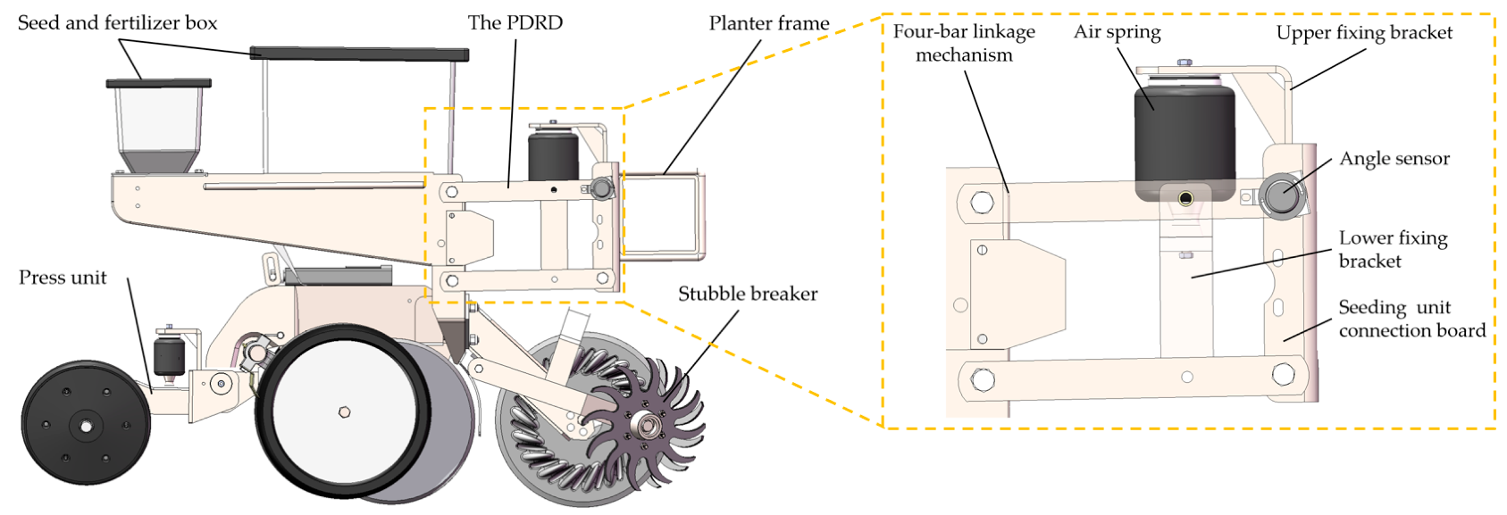
Figure 1. Schematic diagram of the PDRD on the corn no-till planter.
Agriculture 12 01513 g001
Figure 2. Boundary conditions (a) and mesh generation (b) of finite element model.
Agriculture 12 01513 g002
Figure 3. Load steps of the F E analysis: (a) unloaded, (b) first load step, (c,d) second load step, (e) third load step, (f) fourth load step.
Agriculture 12 01513 g003
Figure 4. Structure diagram air spring. (a) Overall Structure (b) Structure of cord layer.
Agriculture 12 01513 g004
Figure 5. The VOF at different times.
Agriculture 12 01513 g005
Figure 6. The internal pressure at different times.
Agriculture 12 01513 g006
Figure 7. Seeding unit downforce test bench.
Agriculture 12 01513 g007
Figure 8. The VOF under different structural parameters.
Agriculture 12 01513 g008
Figure 9. The fitting curve of VOF and VS.
Agriculture 12 01513 g009
Figure 10. The deformation of bellows under different cord angle.
Agriculture 12 01513 g010
Figure 11. The internal pressure under different structural parameters.
Agriculture 12 01513 g011
Table 1. Physical parameters of bellows materials.
CompositionMaterialsModelParameters
Rubber layerRubberMooney–RivlinC10 (MPa)C01 (MPa)
0.51780.1426
Cord layerCord/Young modulus (MPa)Poisson’s ratio
72000.3
Table 2. Single-factor simulation scheme.
NumberFactorVariable’s ValueConditions
1–3Cord angle α30,45,60β = 10°
d1 = 75 mm
4–6Piston angle β5,10,15α = 45°
d1 = 75 mm
7–9Piston diameter d1/mm65,75,85α = 45°
β = 10°
Table 3. The differences between the measured and simulated results.
Height
/mm
Vertical Force Pitch DiameterPressure
Meas/NSimu/NDiff/%Meas/mmSimu/mmDiff/%Meas/MPaSimu/MPaDiff/%
2401824.91892.03.5593.594.51.080.2050.2133.98
2201621.51683.93.7194.395.61.340.2350.2506.18
2001467.41561.76.0495.195.70.660.2760.2987.47
1801265.31297.12.4695.896.40.660.3400.3544.01
1601020.81111.88.1896.896.90.090.4130.4293.74
Note: Meas, Simu and Diff are the abbreviations for measured, simulated and difference.
Table 4. Single-factor simulation scheme.
ObjectCord AnglePiston AnglePitch Diameter
30456051015657585
Average VOF FMv/N2224.31504.21377.61670.51504.21389.61131.61504.22025.9
VS ks/N/mm15.610.89.114.810.87.37.410.815.4
Deformation rate kD/%62.319.23.320.619.219.718.419.222.4
Pressure difference Δp/MPa0.1850.2160.2310.2400.2160.1940.2070.2160.213
Publisher’s Note: MDPI stays neutral with regard to jurisdictional claims in published maps and institutional affiliations.