Article

Design and Test of a Comb-Brush-Type Honeysuckle-Picking Device

1
College of Mechanical and Electrical Engineering, Shihezi University, Shihezi 832003, China
2
Xinjiang Production and Construction Corps Key Laboratory of Modern Agricultural Machinery, Shihezi 832003, China
3
Key Laboratory of Northwest Agriculture Equipment, Ministry of Agriculture and Rural Affairs, Shihezi 832003, China
*
Author to whom correspondence should be addressed.
Agriculture 2023, 13(11), 2088; https://doi.org/10.3390/agriculture13112088
Submission received: 20 September 2023 / Revised: 29 October 2023 / Accepted: 31 October 2023 / Published: 2 November 2023
(This article belongs to the Section Agricultural Technology)

Abstract

:
In response to the issues of high honeysuckle-picking costs and low efficiency in honeysuckle picking, this study has devised a comb-brush-type picking device, considering the unique characteristics of honeysuckle plants. We elucidated the device’s structure and operational principles and designed critical components within the picking mechanism. Subsequently, through theoretical analysis, we identified the primary factors influencing the device’s operational performance. We then used the honeysuckle picking rates, honeysuckle breakage rates, and impurity rates as assessment metrics. Utilizing a one-factor test, we determined the permissible ranges for each factor. Employing the response surface methodology, we analyzed the interactions among these factors and conducted model parameter optimization. This optimization identified the optimal parameter combination: a forward speed of 3.99 km/h, a driving shaft speed of 316.53 rpm, and a picking teeth length of 70 mm. Finally, we performed verification tests using these optimized parameters. The results demonstrated that the maximum relative error between test verification values and model-optimized predictions was 4.86%. This outcome confirms that the comb-brush-type honeysuckle-picking device can meet the operational requirements of mechanized harvesting and offers valuable insights for developing harvesting devices for vine plants.

1. Introduction

Honeysuckle, belonging to the Lonicera family, is a perennial semi-evergreen vine with a rich history of traditional use in herbal medicine [1]. Honeysuckle and its primary constituents have found extensive applications in medicine [2,3,4] and tea products [5,6,7]. Nonetheless, the current method for harvesting honeysuckles relies on manual labor, resulting in the challenges of elevated harvesting expenses and diminished efficiency, which, in turn, hinder the advancement of the honeysuckle industry [8]. As such, there is an imminent need to design field operation machinery suitable for efficiently harvesting honeysuckle.
Honeysuckle is cultivated in places like Japan and Korea [9], but there are few reports and literature on honeysuckle harvesting devices. In China, honeysuckle harvesting devices primarily comprise small, hand-held, or backpack devices. For instance, Zhang Tao et al. [10] devised a backpack honeysuckle picker that employs phase-directed rotating rubber spindles on the picking head to separate flower buds from the branches. Subsequently, the picking device transports the separated flower buds to a rear compartment through a negative pressure conveying tube. A large-scale, highly automated honeysuckle harvesting device is predominantly at the research and development stage. For instance, Gao Shan et al. [11] introduced a self-propelled honeysuckle harvester that employs a ride-on operation, roller picking, and air suction collection to achieve autonomous honeysuckle harvesting. Luo Hongwei et al. [12] also developed a honeysuckle picker designed for the concurrent harvesting of flowers and leaves, utilizing a cutting mechanism at the picking head to sever branches and a rotating drum to separate the flowers and leaves from the branches. Comb-brush-type picking is a prevalent harvesting method in foliage and fruit harvesting machinery. It leverages the differences in attachment strength between the target produce and the plant during the optimal harvesting period, applying force through various picking components to facilitate the separation of the target produce from the plant [13,14,15,16]. For instance, Liu Zhiyuan et al. [17] devised an elastic-tooth drum-type soybean harvesting device, utilizing drum rotation to drive elastic teeth in brushing the pods, thus enabling the harvesting process. Liu Lei et al. [18] developed a castor harvester equipped with flexible brush filaments for picking, achieving an impressive field cleanliness rate of 91.36%. Xu Liming et al. [19] designed a comb-brush vibration-type wolfberry harvesting device with an operational efficiency of up to 13.12 kg/h in field operations. Qiu Lei [20] designed a comb-brush-type picker and collector for hi-tree leaves, employing the rotation of comb teeth to exert force on the leaves, effectively separating branches and leaves. It is worth noting that the comb teeth are made from nylon material, significantly reducing leaf damage.
To sum up, while small-scale harvesting devices aid manual harvesting, they have limitations in terms of efficiency and do not significantly reduce labor demands. On the other hand, large-scale, highly automated honeysuckle harvesting devices are mainly in the research and development phase, with most devices existing as virtual prototypes. The comb-brush-type picking operation proves to be highly efficient and has found successful application in harvesting flowers, leaves, and fruits. This success can serve as a valuable reference for the design of honeysuckle harvesting machinery.
Hence, to address the challenges of high honeysuckle-picking costs and low picking efficiency, this paper has designed a comb-brush-type honeysuckle-picking device based on the planting mode and growth characteristics. This study encompasses the design of crucial components within the picking mechanism, analyzing honeysuckle buds and picking teeth during the picking process, and identifying key factors influencing operational metrics. Employing single-factor testing and Box–Behnken central testing, we have explored parameter ranges, optimized parameters, and validated the results through field testing. This effort aims to provide a reference and a solid research foundation for the subsequent design of honeysuckle harvesting machinery.

2. Materials and Methods

2.1. Structure of the Whole Machine and Working Principle

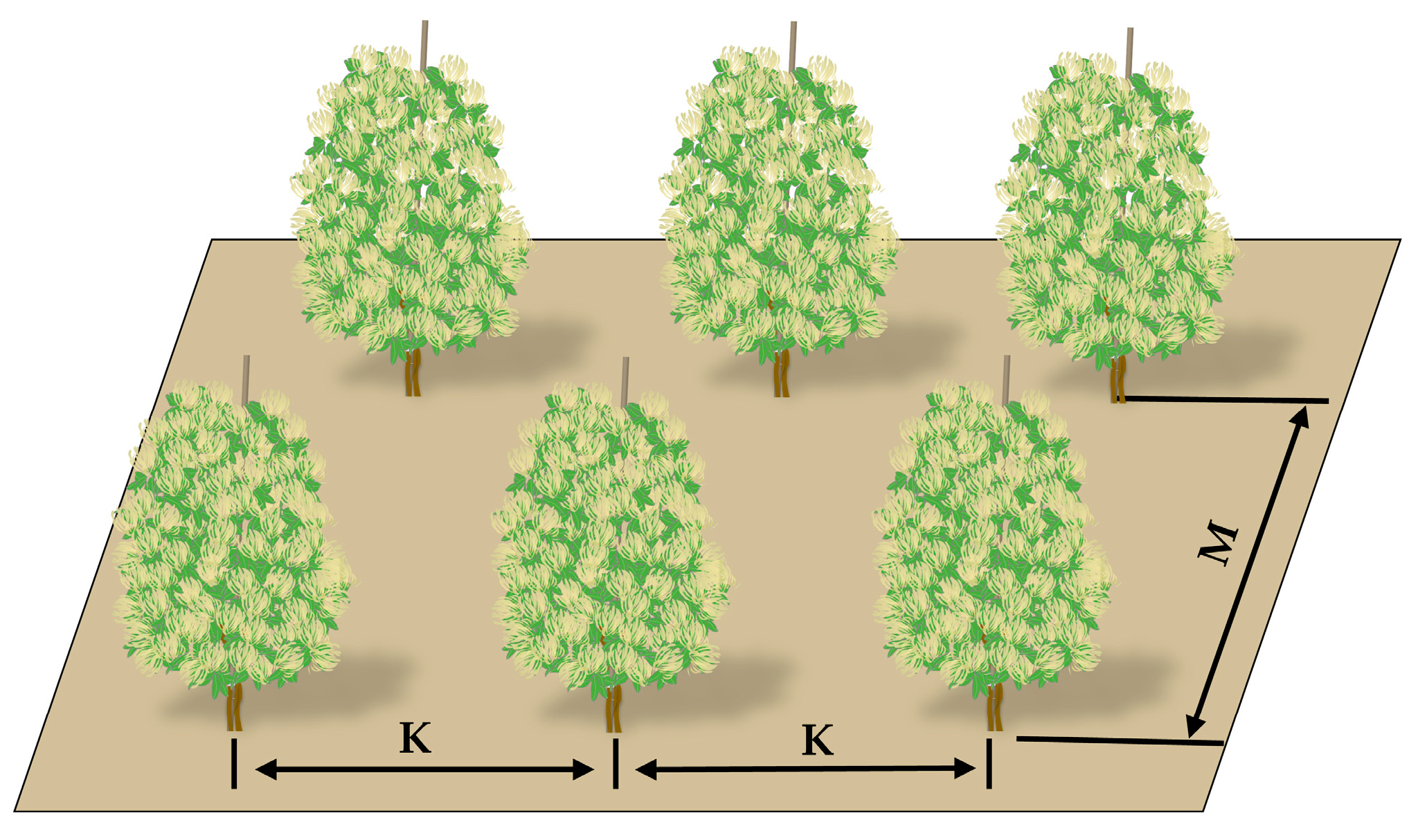
2.1.1. Honeysuckle Cultivation Mode

As of the present, there is no standardized approach to honeysuckle cultivation. Currently, there are four planting modes: “cluster mound shape, single-trunk tree shape, single stake support shape, and trellis vine shape”. Each planting mode has distinct agronomic requirements. This device’s entire design is based on the agronomic practices of honeysuckle cultivation in the 133rd Regiment of Shihezi, Xinjiang, utilizing the single-stake support planting mode. The planting configuration features a row spacing M of 1.5 m and a plant spacing K of 1.3 m, as illustrated in Figure 1.

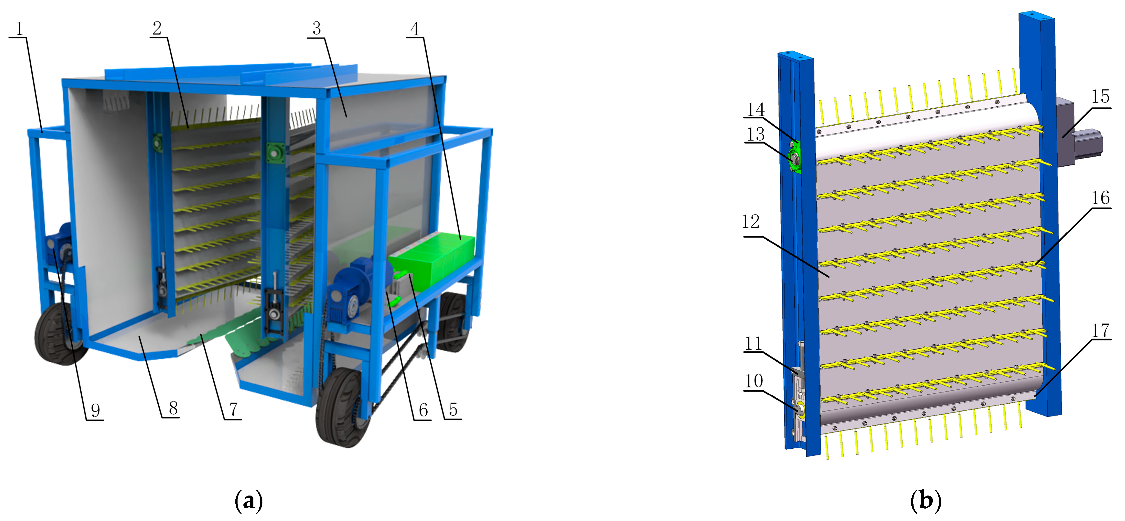
2.1.2. Structure of the Whole Machine

The comb-brush-type honeysuckle-picking device consists of a frame 1, a picking mechanism 2, a shell cover 3, a 48V battery pack 4, a picking motor controller 5, a walking motor controller 6, a scale plate mechanism 7, a flower-catching plate 8, and a walking DC motor 9. We depict the structural schematic diagram of the device in Figure 2a. The central component of the device is the picking mechanism, which includes a driven shaft 10; a tension bearing seat 11; a picking belt 12; a driving shaft 13; a square bearing seat 14; a picking DC motor 15; picking teeth 16; and a T-belt 17, as illustrated in Figure 2b. The driving and driven shafts create tension in the picking belt, and the DC gear motor is directly linked to the driving shaft. The T-belt is connected to the picking belt through vulcanized bonding, while the picking teeth comprise a connecting iron piece and picking teeth, which are securely fastened to the T-belt using bolts.

2.1.3. Working Principle

The device is powered by a DC gear motor, driving the picking mechanism and propelling the device. The walking DC motor controller is equipped with a wireless control module, enabling the control of the device’s movement and turning using the handle. Before commencing the operation, the operator must ensure they correctly align the device with the plants. The picking mechanism should be running smoothly before starting the operation. During the operation, since the picking mechanism is installed in a “V” shape, as the device moves forward, the picking teeth gradually move closer to the main stem of the honeysuckle plant. They brush the honeysuckle branches from the bottom to the top, causing an instantaneous acceleration of the flower buds on the branches. When the force exerted by the flower buds overcomes the connecting force of the flower stalks, the flower buds separate from the stalks. After the plant passes through the preceding scale plate, the scale plate automatically resets under the influence of the tension spring. The scale plate consistently forms a closed space with the surrounding shell cover, ensuring that most dislodged flower buds fall directly into the flower-catching plate. The scale plate is connected to the frame of the flower-catching plate at a specific angle, allowing some of the scattered flower buds on the scale plate to naturally slide into the flower-catching plate, thus facilitating the honeysuckle harvesting operation.

2.2. Design of Critical Components for a Comb-Brush-Type Picking Mechanism

2.2.1. Width of the Picking Belt

Figure 3 provides a top-down view illustrating the positioning of the picking mechanism of the honeysuckle plant during the device’s operation.
In order to ensure the effective picking of flower buds, it is crucial to adjust the width of the picking belt and the angle at which it is installed to align with the growth characteristics of the honeysuckle plant. Therefore, the picking belt in a plane parallel to the ground must adhere to the following equation:
L D s 2 sin θ
where L is the width of the picking belt, mm; θ is the angle between the picking belt and the forward direction, rad; s is the distance of the back picking teeth, m; Vm is the forward speed of the device, m/s; and D is the distance of the front picking teeth, m.
For the single-stake support planting mode of honeysuckle, it is crucial to ensure that S can easily pass through the main stem of the honeysuckle plant. In order to guarantee the picking quality of the device, S was determined to be 1.5 times the average diameter of the main stem. Based on prior measurements of the characteristics of honeysuckle plants, the main stem’s average diameter was 40 mm. Consequently, S was 60 mm. The selection of the angle between the picking belt and the forward direction, as well as the distance between the front ends of the picking teeth, was based on the diameter of the flowering area of the honeysuckle plant and practical considerations. In this case, θ was 15° and D was 500 mm. According to the calculation of Equation (1), we determined that L should be equal to or greater than 846 mm. In order to avoid unnecessarily increasing the size of the picking mechanism, we made the final decision to set L at 900 mm.

2.2.2. Picking Radius

Honeysuckle plants densely distribute flower buds from the lowest knotting point of the plant to the top and surrounding area. To ensure effective picking and a well-designed device structure, the distance from the endpoint of the picking tooth to the center of the drive shaft radius (referred to as picking radius R) should meet the following criteria: the lowest point of the tooth should be lower than the minimum height of the flower-receiving location, the overall height of the picking tooth picking area should exceed the height of the flower-knotting on the honeysuckle plants, and there should be a certain distance between the tooth and the ground to allow for the design of the flower-catching mechanism and to ensure that the device can navigate natural terrain. Figure 4 provides a schematic representation of the picking mechanism for the honeysuckle plant’s position.
To ensure the requirements above, we need to satisfy the following equation when assuming that the picking teeth rotate by α to reach the lowest picking point:
cos α · R + H 2 > R 2 R cos α + B H 1
where B is the center distance of the picking belt, m; H1 is the height of the honeysuckle flower formation, m; and H2 is the height of the lowest bud above the ground, m.
The collation of Equation (2) leads to a range of values for the picking radius R, which can be expressed as follows:
H 1 B 2 cos α R < H 2 1 cos α
At this point, the lowest part of the picking tooth is located at a distance H3 from the ground:
H 3 = H 2 R ( 1 cos α )
The central linear portion of the picking belt, which serves as the primary picking area for flower buds, should cover the flower bud setting region as extensively as possible. Considering the characteristics of the honeysuckle plant and practical circumstances, the center distance of the picking belt (denoted as B) is 870 mm. The average height of honeysuckle flower formation (H1) is 1200 mm, and the average height of the lowest flower bud above the ground (H2) is 280 mm. As per Equation (4), when R is determined, a larger angle α results in a smaller height for picking teeth from the ground. Hence, in alignment with design requirements and practical considerations, α is 40°. Subsequently, based on Equation (3), the value range for R falls between 136 mm and 870 mm. With α set at 40° and H3 at 230 mm, R equals 217 mm. We ultimately fix R at 200 mm for subsequent processing and design.

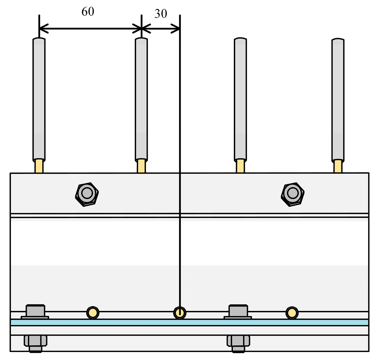
2.2.3. Design of Picking Teeth

The diameter of honeysuckle plant branches typically ranges from about 5 mm to 20 mm, while the diameter of clustered flower spikes falls within about 50 mm to 80 mm. Picking teeth spacing is designed based on the branch diameter and clustered flower spike diameter. If the spacing is too small, it can lead to branch damage; if it is too large, it may not effectively comb-brush the branches. Picking teeth on the picking belt adopt an alternating distribution of adjacent picking rows to ensure effective picking. In other words, the spacing between the picking teeth in the same row is 60 mm, and the spacing between the adjacent rows of picking teeth is 30 mm. Figure 5 depicts the arrangement of the picking teeth.
Honeysuckle flower buds grow in clusters, and the picking teeth must brush the flower bud area multiple times within a specific timeframe to ensure effective picking. Consequently, the design includes 18 rows of picking teeth. Each row features individual picking rod teeth made from 60Si2Mn spring steel and covered with a silicone hose on the surface. This design enables effective brushing of the flower buds while reducing the risk of bud damage. The length of the picking teeth directly affects the picking range: longer picking teeth result in a more extensive range but reduce the plant’s ability to pass through, while shorter picking teeth reduce the effective picking area. Based on the processing requirements, the driving and driven shafts have a diameter of 120 mm, the picking belt has a thickness of 3 mm, and the picking radius is 200 mm, so the picking tooth length should not exceed 77 mm.

2.2.4. Design of the T-Belt

As a connecting component between the picking tooth bars and the picking belt, the T-belt plays a critical role in picking efficiency and operational stability. Therefore, we treat the picking teeth as external loads and analyze them based on the cross-section of a single T-belt. To simplify the model, one end of the T-belt is bonded to the picking belt with adhesive, making this part effectively a fixed end.
From Figure 6, we have the following T-belt force analysis:
F x = F f cos θ A F H sin θ A F y = F H cos θ A + G + F f sin θ A F f = z μ 1 F N
where Fƒ is the friction force of the picking teeth on the T-belt, N; Fx is the horizontal component of the force of the picking teeth on the T-belt at the fixed end, N; Fy is the vertical component of the force of the picking teeth on the T-belt at the fixed end, N; FH is the combined force of the picking teeth on the T-belt, N; μ1 is the coefficient of friction of the picking teeth on the T-belt; θA is the angle of the friction force Fƒ when it is parallel to the T-belt (°); z is the number of bolts on the picking teeth; and FN is the positive pressure on the T-belt, N.
During operation, T-belts experience bending due to a combination of forces. As a result, the bending moment MB at point B, which is located at a distance A from the fixed end, can be expressed as follows:
M B = F H cos θ A + G + F f sin θ A L T S
The stress σt caused by the horizontal component of the force exerted by the picking teeth on the T-belt at point A is expressed as follows:
σ t = F x Q = F f cos θ A F H sin θ A Q
where Q is the cross-sectional area of the T-strip, m2.
The bending stress experienced by the T-belt at point B is expressed as follows:
σ b = M B W = F H cos θ A + G + F f sin θ A L T S W
where W is the bending section coefficient of the T-belt.
According to the principle of stress superposition [21], the composite stress at point B on the T-belt cross-section is the sum of the bending stress σb and the axial stress σt, resulting in the following:
σ Z = σ t + σ b = F f cos θ A F H sin θ A Q + F H cos θ A + G + F f sin θ A L T S W
Equations (6) and (9) reveal that the greater the external force acting on the T-belt, the larger the bending moment and combined stress, making it more susceptible to bending and failure. During operation, when the picking teeth encounter dense branches, the resistance to the picking teeth increases, resulting in an increased force on the T-belt, and both the combined stress and bending moment increase. To ensure the stability of the picking teeth and picking effectiveness, it is essential to meet the strength requirements of the T-belt, with the composite stress being less than the ultimate stress of the T-belt.
In order to select the material for the T-shaped belt and establish its structural parameters, this analysis focuses on the bending deformation of the T-belt. To facilitate the calculation, we approximate the bending deformation of the T-belt as a linear elasticity problem. The bending deformation of the T-belt is a linear elasticity problem. This approach allows for the determination of the angle of twist and the maximum deflection of the cross-section [22], which is given by the following:
θ B = ( F H cos θ A   +   G   +   F f sin θ A ) L T 2 2 E I W B = ( F H cos θ A   +   G   +   F f sin θ A ) L T 2 6 E I ( 3 L L T )
where θB is the T-belt cross-section’s maximum deflection, m; WB is the T-belt rotation angle, rad; E is the T-belt Elastic modulus, Gpa; and I is the T-belt moment of inertia, m4.
Equation (10) shows that the rotation angle of the T-belt and the maximum deflection of its cross-section have an inverse relationship with the modulus of elasticity and the moment of inertia. They are positively related to the external force applied to the T-belt and the location of the force. When the modulus of elasticity of the T-belt material and the cross-section moment of inertia are more significant, the T-belt’s rotation angle and deflection are minor, indicating increased resistance to deformation. In this scenario, the picking teeth are more likely to cause damage to the branches and buds. Conversely, when the modulus of elasticity and moment of inertia are smaller, the picking teeth can bend more easily during brushing, resulting in reduced brushing force. Additionally, the closer the connection point between the picking teeth and the T-belt is to the fixed end, the less the T-belt is deformed by external forces. Hence, we constructed the T-belt from PU polyurethane, with a cross-section designed to be 30 mm in length and 5 mm in width, and the picking teeth are installed as close as possible to the root of the T-belt.

2.3. Analysis of the Picking Process

The picking teeth exert random forces on flower buds, leaves, and branches in the picking process, leading to a complex operational scenario. To investigate the primary factors influencing picking performance, we simplified and analyzed the process of picking teeth when engaging with flower buds, the movement of the picking teeth, and the forces applied by the picking teeth.

2.3.1. Analysis of the Picking Process by Picking Teeth

Assuming that the ends of the picking teeth make contact with the bottom of the flower bud during the picking process, Figure 7 illustrates the force exerted on the flower bud.
The various forces acting on the bud can be resolved along the coordinate axes as follows:
F V sin θ A + T cos = f cos θ A F V cos θ A + f sin θ A = m g + T sin
where G is the self-generated gravity force of the bud, N; FV is the force of the picking teeth on the bud during the picking operation, N; T is the branch-bud connection force, N; f is the friction force of the picking teeth on the bud during the picking operation, N; θA is the angle of the picking teeth, rad; and is the angle of the honeysuckle bud pulling force, rad.
In the process of honeysuckle picking, simplifying the friction force of the picking teeth on the buds can be expressed as follows:
f = μ F n F n = F V G cos θ B T sin ( θ B )
where μ is the friction coefficient between the bud and the picking teeth, N, and Fn is the positive pressure on the bud during picking, N.
By combining Equations (11) and (12), we can express the force exerted by the picking teeth on the buds as follows:
F V = G cos θ B + T sin ( θ B ) tan tan θ μ cos θ + m g tan tan θ cos θ 1 ( 1 + tan θ tan ) μ cos θ
As per Equation (13), the force applied by the picking teeth to the buds is influenced by several factors, including the picking angle, the friction coefficient between the buds and the picking teeth, the angle at which the buds are pulled, the mass of the buds, and the connection force between the branch and the buds. The T-belt material determines the picking angle, and it may be challenging to ensure uniformity in the bud pull angle and connectivity across various parts of the plant. The friction coefficient between the buds and the picking teeth can be adjusted by changing the material of the picking teeth. Equation (13) also indicates that the force the picking teeth apply to the buds increases with the higher surface friction coefficient of the picking teeth. To ensure the effective picking of flower buds by the picking teeth, we treated them by inserting a 2 mm thick silicone hose over their surface. This treatment increased the surface friction coefficient while reducing damage to the branches.

2.3.2. Analysis of the Picking Tooth Movement Process

The center distance of the picking belt in the straight section serves as the primary working area, and we analyzed the motion of the picking teeth in this region. During operation, the motion within the space of the picking teeth is composed of two movements: the forward motion of the device and the upward motion of the picking teeth from bottom to top.
As shown in Figure 8, the absolute velocity of the picking teeth in space is expressed as follows:
v a = v e + v m
where Vm is the forward speed of the device, m/s; Va is the absolute speed of the picking teeth, m/s; and Ve is the linear speed of the linear region of the picking belt, m/s.
Ve is the linear velocity in the linear region of the picking belt’s motion, and the expression is as follows:
v e = 2 π n R 60
where n is the driving shaft speed, rpm.
Therefore, we can express the absolute velocity of the picking teeth as follows:
v a = v e 2 + v m 2 = v m 1 + v e v m 2
Defining the ratio of the linear velocity of the picking tooth’s end to the device’s forward speed as λ, we can rewrite Equation (16) as follows:
v a = v m 1 + λ 2
The driving shaft speed is then correlated with the forward speed as follows:
n = 30 v e π R = 30 λ v m π R
Substituting Equation (17) into Equation (18) yields the following correlation between the driving shaft speed and the absolute speed of the end of the picking tooth:
n = 30 λ v a π R 1 + λ 2
According to Equations (18) and (19), once the coefficient λ is determined, the driving shaft speed exhibits a positive correlation with both the absolute speed of the picking teeth’s end and the device’s forward speed. Given the brief flowering period of honeysuckle, the device must operate with high efficiency. In other words, a faster forward speed is preferable. However, as the forward speed increases, so does the corresponding rotational speed of the driving shaft, leading to a higher absolute speed at the end of the picking teeth. The absolute speed reflects the size of the picking teeth’s impact on the buds—excessively high absolute speed results in increased honeysuckle bud damage and impurities. Consequently, selecting the appropriate forward speed and driving shaft speed is crucial for achieving efficiency and maintaining the quality of honeysuckle picking.

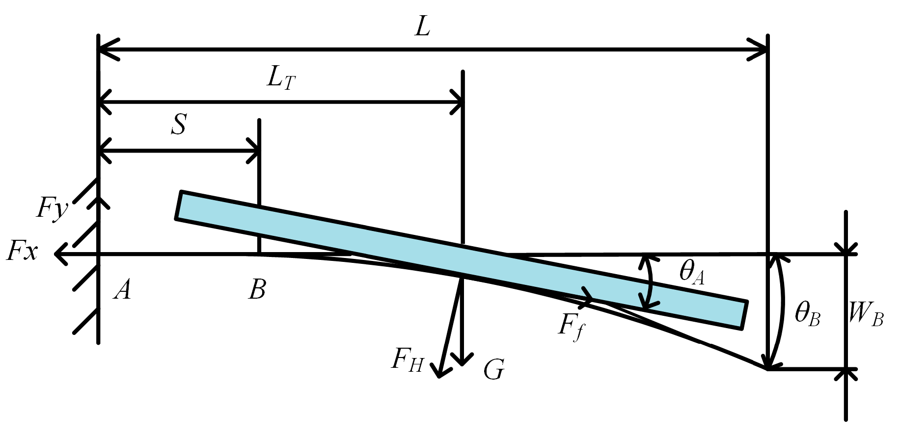
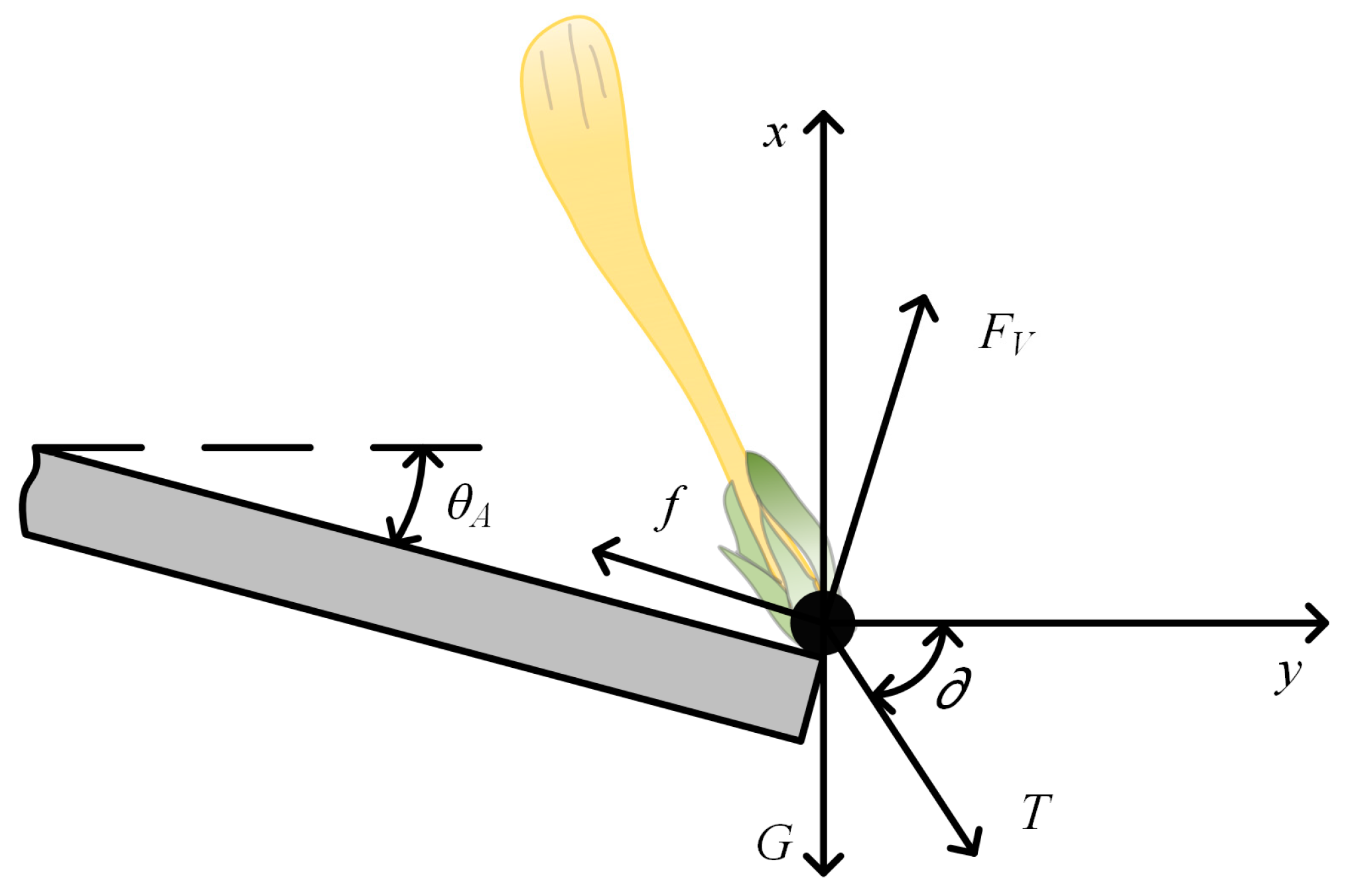
2.3.3. Picking Tooth Strike Force Analysis

The picking teeth come into contact with the buds, leaves, and branches throughout the picking process. The magnitude of the striking force applied by the picking teeth directly affects the effectiveness of the picking operation. As such, we analyzed the striking force of the picking teeth. We made certain assumptions as follows: we assumed that during the striking action, the striking portion of the picking tooth and the picking tooth itself engage in a centripetal collision. The cross-section of the picking tooth is considered circular, and we simplified the striking part as a uniform mass sphere. Furthermore, friction between the bud’s rotation, the picking tooth, and the bud during the striking process was disregarded [23,24,25]. We applied the Hertzian theory and depicted the force relationship of the picking teeth on the striking site in Figure 9.
F = 4 3 E * R * δ 3 2
where F is the striking force of the picking teeth on the bud, N, and δ is the striking deformation, m.
The equivalent modulus of elasticity and the equivalent radius are defined as follows:
1 E * = 1 μ 1 2 E 1 + 1 μ 2 2 E 2 1 R * = 1 R + 1 r
where E* is the integrated modulus of elasticity; E1, E2 is the modulus of elasticity of the picking teeth and the striking part; μ1, μ2 is the Poisson’s ratio of the picking teeth and the striking part; R* is the equivalent radius of deformation, mm; R, r is the radius of the picking teeth and the striking part, mm.
From Equation (20), we can observe that various factors influence the striking force of the picking teeth, including the composite modulus of elasticity, Poisson’s ratio of the picking teeth and the striking part, the equivalent deformation radius, and the degree of striking deformation. The modulus of elasticity and Poisson’s ratio are inherent material properties. Consequently, the key determinants affecting the force applied by the picking tooth are the equivalent deformation radius and the amount of striking deformation. These two factors are affected by the absolute velocity of the picking tooth spacing and the striking site. Hence, it is possible to control the magnitude of the picking tooth striking force by regulating the speed of the picking motor, the forward speed, and the length of the picking teeth.

2.4. Performance Test of the Honeysuckle-Picking Device

2.4.1. Test Condition

The test site was in the honeysuckle cultivation area of the 133rd regiment in Shihezi City, Xinjiang Production and Construction Corps. The honeysuckle variety used was “Bei flower No.1”; it was cultivated using a single-stake support planting mode. The average distance between the rows was 1.5 m, the average spacing between the plants was 1.3 m, and the average plant height was 1.4 m. The moisture content of the honeysuckle buds varied between 34.37% and 46.97%, while the lignified stalks had a moisture content ranging from 38.94% to 44.64%.

2.4.2. Test Apparatus and Device

The test setup consisted of a honeysuckle-picking test device using a comb-brush design, as illustrated in Figure 10. It included the following apparatus: a DT2234C photoelectric tachometer (with a measurement range of 2.5–99,999 rpm and a resolution of 0.1 RPM), an MTC005 high-precision counting scale (MeilenMTC005, with a range of 0 kg–10 kg and a precision of 0.1 g), vernier calipers (with a precision of 0.02 mm), a 50 m tape measure, and several mesh bags for collecting the harvested honeysuckle.

2.4.3. Test Methods

Based on the theoretical analysis presented earlier, it is evident that the critical factors influencing the efficiency of the picking process include forward speed, driving shaft speed, and the length of the picking teeth. In order to assess the impact of these critical factors, we conducted a single-factor test to determine the parameter ranges of these key factors, followed by an optimization process using an orthogonal test. As there are currently no specific technical standards related to honeysuckle harvesting machinery, this test referred to established technical standards like “Harvesting Machinery Test Methods for Combine Harvester” (GB/T 8097-2008) [26] and “Grade Specification of Agricultural Products Honeysuckle” (NY/T 2303-2013) [27] to establish evaluation criteria and testing procedures. We outline the details of these evaluation criteria and testing methods as follows:
  • Honeysuckle picking rate Y1
Three honeysuckle plants with similar morphology, located consecutively in the same row, were chosen as the subjects for each test. Each test was conducted after the device had reached a stable operational state. We calculated the picking rate using Equation (22), and each test was repeated three times, with the average of these results being considered the outcome.
Y 1 = W 1 W 1 + W 2 + W 3 × 100 %
where Y1 is the honeysuckle picking rate, %; W1 is the mass of honeysuckle picked and knocked down in the flower catcher plate, g; W2 is the total mass of honeysuckle remaining on all plants in the test area, g; and W3 is the total mass of honeysuckle dropped on the ground in the sampling area, g.
2.
Honeysuckle breakage rate Y2
The collected materials from the harvested honeysuckle were processed, and the broken honeysuckle buds were selected and weighed. We calculated the breakage rate using Equation (23), and each test was repeated three times, with the average of these results being considered the outcome.
Y 2 = W 4 W 1 × 100 %
where Y2 is the honeysuckle breakage rate, %; W4 is the mass of honeysuckle picked and broken in the sampling area, g; and W1 is the mass of honeysuckle picked and knocked down in the splice plate, g.
3.
Impurity rate Y3
The total harvested material collected on the flower-catching plate was weighed, and impurities were separated and weighed. We calculated the impurity rate using Equation (24), and each test was repeated three times, with the average of these results being considered the outcome.
Y 2 = W 5 W 6 × 100 %
where Y3 is the impurity rate, %; W5 is the impurity mass on the flower-catching plate in the sampling area, g; and W6 is the mass of all materials in the flower-catching plate, g.

2.4.4. Single-Factor Test Design

In order to determine the parameter ranges for the influencing factors, single-factor tests were conducted on the evaluation indicators [28,29]. In the single-factor test for forward speed, the driving shaft speed was 350 rpm, the picking teeth length was 65 mm, and the forward speed range was from 1 km/h to 6 km/h. In the single-factor test for driving shaft speed, the forward speed was 2 km/h, the picking teeth were 65 mm long, and the driving shaft speed range was from 250 rpm to 500 rpm. In the single-factor test for picking tooth length, the forward speed was 2 km/h, the driving shaft speed was 350 rpm, and the picking tooth length range was from 50 mm to 75 mm. We conducted each test three times and averaged the final results.

2.4.5. Orthogonal Test Design

To determine the optimal parameters of the device, we employed the Box–Behnken test design method [30,31]. This involved conducting a three-factor, three-level quadratic orthogonal rotary center combination test. The influencing factors were forward speed, driving shaft speed, and the length of the picking teeth. The evaluation indicators included the honeysuckle picking rate, honeysuckle breakage rate, and the impurity rate. Table 1 presents the coding table for the test factor levels.
The test design software Design-Expert 11.0 was employed to create a three-factor, three-level Box–Behnken test plan. This plan consisted of 17 test groups, including 12 for analyzing factors and 5 for zero-point estimation error. Each test group was repeated three times, and we determined the final test results as the average of these repetitions.

3. Results

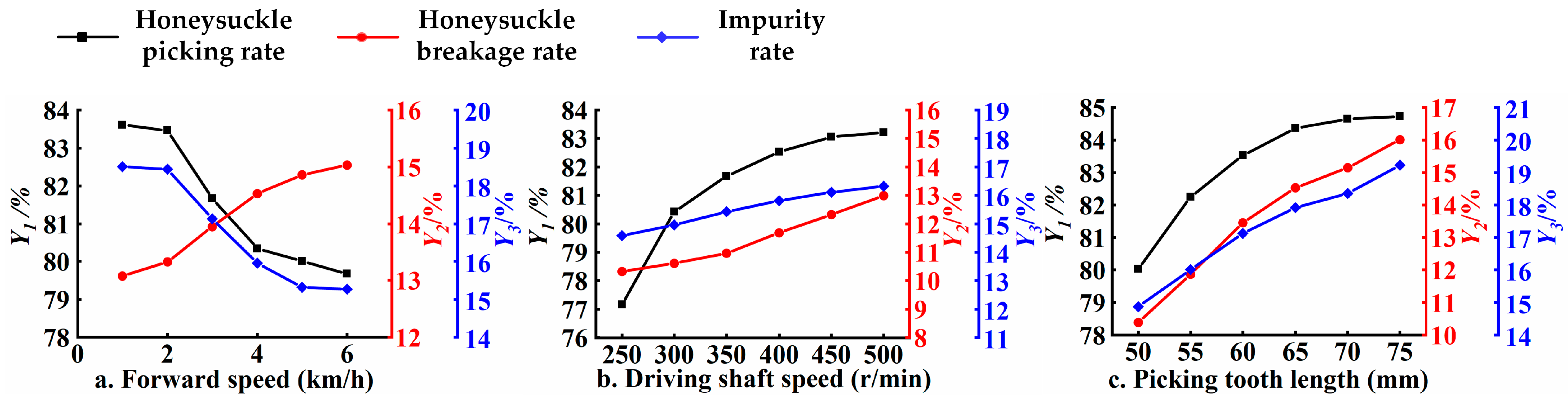
3.1. Results and Analysis of the Single-Factor Test

We depict the results of the single-factor test in Figure 11.
As shown in Figure 11a, the honeysuckle picking and impurity rates show a decreasing trend with increasing forward speed, while the honeysuckle breakage rate shows an increasing trend. The reason is that higher forward speeds result in shorter contact times for the picking teeth, leading to a lower picking rate and impurity rates. Furthermore, the more excellent forward speed results in higher absolute speeds of the picking teeth, increasing the force applied to the buds and raising the honeysuckle breakage rate. Forward speeds ranging from 2 km/h to 4 km/h significantly affect the evaluation indexes. We conducted subsequent optimization tests within this range.
As shown in Figure 11b, the honeysuckle picking rate, the honeysuckle breakage rate, and the impurity rate exhibit an increasing trend with the rise in driving shaft speed. The driving shaft speed impacts the picking tooth space’s absolute speed, affecting the picking teeth’ striking force on both the flower buds and branches. When the picking speed is too low, the striking force applied to the flower buds is insufficient for proper separation from the stems. Conversely, the force exerted by the picking teeth increases at higher driving shaft speeds, leading to potential damage to the flowers, leaves, and branches, resulting in higher honeysuckle breakage and impurity rates. With driving shaft speeds exceeding 300 rpm, the picking rate continues to rise. When driving shaft speeds exceed 450 rpm, the honeysuckle picking rate tends to stabilize. However, the impurity and honeysuckle breakage rates still show an upward trend. Consequently, we conducted subsequent optimization tests at speeds ranging from 300 rpm to 450 rpm.
As shown in Figure 11c, the length of the picking teeth positively correlates with the picking rate, breakage rate, and impurity rate. The length of the picking teeth determines the size of the picking range. The longer the picking teeth, the more extensive the picking range, and a greater force at the end of the picking teeth leads to an increase in picking rate, breakage rate, and impurity rate. It is important to note that there are fewer flower buds near the main stem. Therefore, when the length of the picking teeth exceeds 70 mm, the upward trend in the picking rate decreases. However, the breakage rate and impurity rate still exhibit an upward trend. When the length of the picking teeth surpasses 60 mm, the increase in picking rate slows down. It becomes apparent that when the length of the picking teeth is within the range of 60 mm to 70 mm, the picking range substantially covers the area where flower buds are distributed. Consequently, subsequent optimization experiments were carried out with picking tooth lengths ranging from 60 mm to 70 mm.

3.2. Orthogonal Test Results and Analysis of Variance

Table 2 outlines the orthogonal test scheme and outcomes. The test data underwent processing and analysis using Design-Expert 11.0 software to formulate regression models for the honeysuckle picking rate (Y1), the honeysuckle breakage rate (Y2), and the impurity rate (Y3) about the forward speed (A), the driving shaft speed (B), and the length of the picking teeth (C). Subsequently, we conducted ANOVA for each model.
The results of the ANOVA for the honeysuckle picking rate are displayed in Table 3. In this table, the p-value of the honeysuckle picking rate model is less than 0.01, while the p-value of the misfit term exceeds 0.05, indicating a high model fit. Parameters A, B, C, A2, and B2 exhibit extremely significant effects on the Y1 model of honeysuckle picking rate, and AB significantly affects the Y1 regression model. The significance of the parameters’ main linearity and interaction effects on the net harvesting rate follows the order of B, A, C, AB, AC, and BC in descending order. The regression equation was refined by removing the non-significant parameters, resulting in the optimized regression equation for the honeysuckle picking rate as follows:
Y 1 = 3.89 + 11.40 A + 0.29 B + 0.25 C + 0.01 A B 2.82 A 2 0.0004 B 2
The results of the ANOVA for the honeysuckle breakage rate are displayed in Table 3. In this table, the p-value of the honeysuckle breakage rate model is less than 0.01, while the p-value of the misfit term exceeds 0.05, indicating a good model fit. Specifically, parameters B, A2, and B2 exhibit extremely significant effects on the Y2 model of honeysuckle breakage rate, and the effects of A, C, and BC on the Y2 regression model are significant. The significance of each parameter’s primary linearity and interaction effects on the breakage rate follows the order of B, C, A, BC, AB, and AC in descending order of significance. After eliminating the insignificant parameters, the regression equation for the honeysuckle breakage rate was optimized and is as follows:
Y 2 = 136.92 + 15.29 A + 0.45 B + 1.15 C 0.0027 B C 2.67 A 2 0.0003 B 2
The ANOVA results for the impurity rate are displayed in Table 3. The p-value of the impurity rate model is less than 0.01, while the p-value of the misfit term exceeds 0.05, indicating a solid fit for the model. Among the factors, B, A2, and B2 had extremely significant effects on the Y3 model of impurity rate, and A, C, AB, and BC had significant effects on the Y3 regression model. The significance of each parameter’s primary linearity and interaction effects on the impurity rate ranked in descending order as B, A, C, BC, AB, and AC. After removing the non-significant parameters, the regression equation for the impurity rate was optimized and obtained as follows:
Y 3 = 115.23 + 9.89 A + 0.40 B + 1.147 C + 0.013 A B 0.0027 B C 2.59 A 2 0.0003 B 2

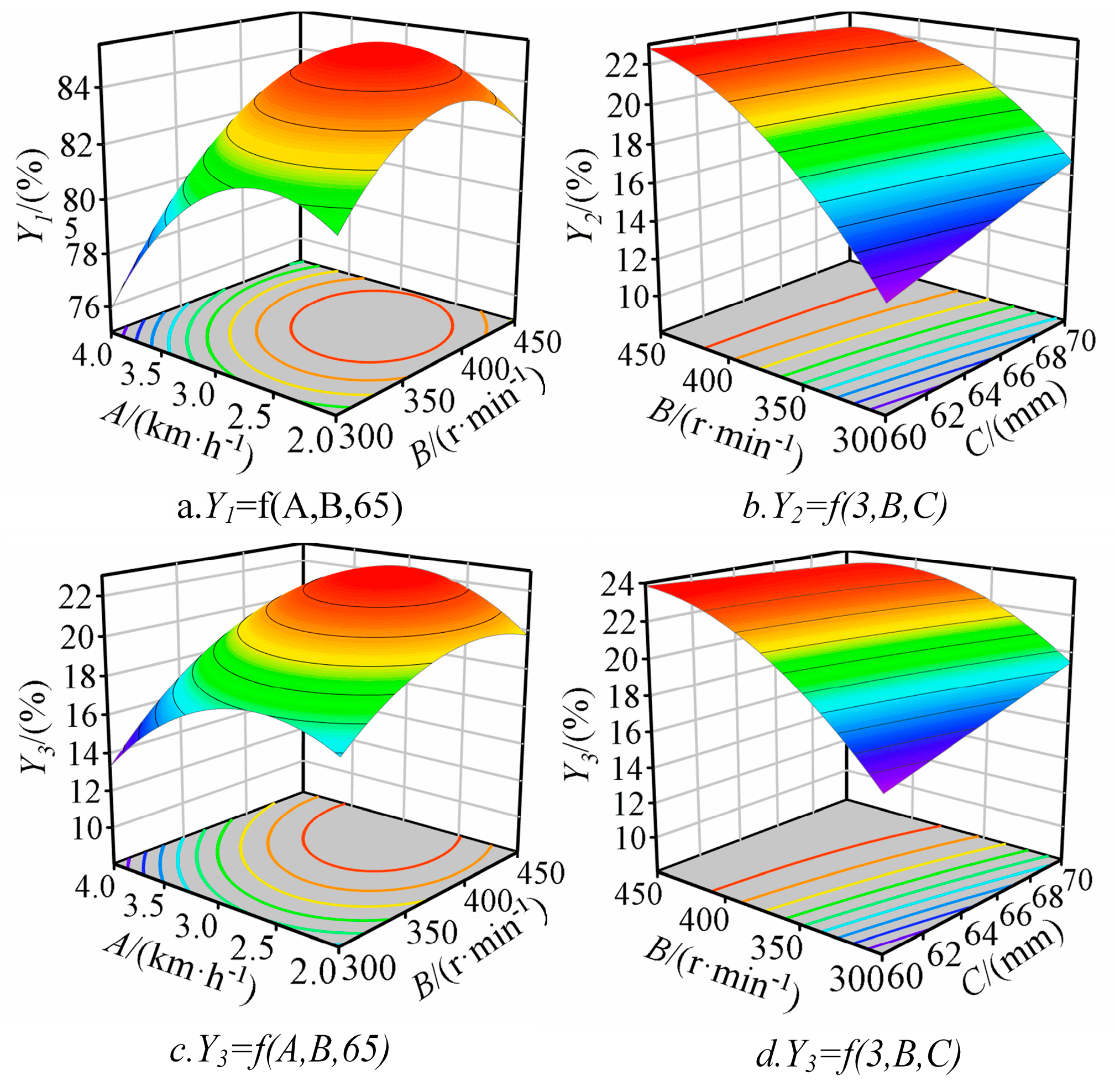
3.3. Response Surface Analysis

We further examined the impact of the interaction between forward speed, driving shaft speed, and picking tooth length on the response variable through response surface plots.
The response surface plots illustrating the interaction between forward speed and driving shaft speed regarding the honeysuckle picking rate are presented in Figure 12a. When the picking teeth were 65 mm long, the honeysuckle picking rate increased with increasing driving shaft speed under the same forward speed. However, the honeysuckle picking rate declined after reaching a certain driving shaft speed. The reason is that as the driving shaft speed increases, the striking force of the picking teeth on the flower buds increases, resulting in an enhanced picking rate. However, when the driving shaft speed reaches a certain threshold, the force on the flower buds becomes excessive, causing the flower buds to be thrown from the collection area, thereby reducing the picking rate. With the same driving shaft speed, the honeysuckle picking rate decreased as the forward speed increased. The reason is that the increased forward speed led to a reduction in the duration and frequency of the combing of the picking teeth, resulting in instances of missed picking.
The response surface plots illustrating the interaction between the driving shaft speed and picking tooth length regarding breakage rate are presented in Figure 12b. At a horizontal value of 3 km/h for forward speed, the honeysuckle breakage rate increased with both the length of the picking teeth and the driving shaft speed, with a significant interaction effect. Augmenting the length of the picking teeth and the driving shaft speed translates to an expanded picking area and heightened force exerted by the picking teeth on the flower buds, consequently leading to an increase in the breakage rate. Therefore, selecting the appropriate driving shaft speed and tooth length is crucial to ensure an effective picking process and minimize flower bud breakage.
The response surface plots illustrating the interaction between forward speed and driving shaft speed on impurity rate are presented in Figure 12c. When the picking tooth length is 65 mm, there is a positive correlation between the impurity rate and driving shaft speed and a negative correlation with the forward speed. The reasons attributed to increasing the driving shaft speed augments the force the picking teeth exert on the flowers, leaves, and branches. Decreasing the forward speed prolongs the action time of picking teeth on the flowers, leaves, and branches, potentially disrupting the shoots or dislodging the leaves, thereby increasing the impurity rate.
The response surface plots illustrating the interaction between driving shaft speed and picking tooth length on impurity rate are presented in Figure 12d. When the forward speed is 3 km/h, there is a notable increase in the impurity rate with the rise in both picking tooth length and driving shaft speed. While increasing the picking tooth length and driving shaft speed extends the picking range and enhances the force exerted by the picking teeth, it also leads to a higher likelihood of knocking off more leaves. Hence, selecting the appropriate driving shaft speed and picking tooth length can effectively reduce impurity rates.

3.4. Parameter Optimization and Test Validation

3.4.1. Parameter Optimization

In order to enhance the honeysuckle picking rate while minimizing both the honeysuckle breakage rate and the impurity rate, we employed Design-Expert 11.0 software to optimize the influencing factors. Given the brief flowering window of honeysuckle, operational efficiency becomes crucial in the context of honeysuckle harvesting machinery. This implies that one should maximize the forward speed while ensuring optimal picking quality. Therefore, we considered the following constraints:
m a x i m i z e Y 1 ( A , B , C ) m i n i m i z e Y 2 ( A , B , C ) m i n i m i z e Y 3 ( A , B , C ) s . t . 2   km / h A 3   km / h m a x i m i z e A 300   r / min B 450   r / min 60   mm C 70   mm
The calculated optimal parameters are a forward speed of 3.99 km/h, a driving shaft speed of 316.53 rpm, and picking teeth length of 70 mm. Under these conditions, the honeysuckle-picking device achieves a picking rate of 79.59%, a breakage rate of 11.46%, and an impurity rate of 14.31%. This demonstrates that the operational performance of the honeysuckle-picking device has reached its peak efficiency.

3.4.2. Test Validation

In order to confirm the accuracy of the parameter optimization, we conducted three tests to validate the previously determined parameters: a forward speed of 3.99 km/h, a driving shaft speed of 316.53 rpm, and a picking teeth length of 70 mm. The field test plot of the comb-brush-type honeysuckle-picking device is shown in Figure 13. The final results are the average of three tests as shown in Table 4.
The table reveals that the relative errors between the model-optimized values and the test validation values for the honeysuckle picking rate, honeysuckle breakage rate, and impurity rate are 1.43%, 4.86%, and 3.12%, respectively. These results indicate the reasonableness of the model-optimized values and the high fit of the model. The optimized parameter values from the model serve as valuable references for determining the optimal parameters of the honeysuckle-picking device.

4. Discussion

(1)
The picking rod teeth are designed as rigid inside and flexible outside. While this design helps protect the branches, it can lead to issues like leaf detachment and bud breakage. Subsequent research can focus on optimizing the material of the picking times to reduce both the breakage and impurity rates.
(2)
The primary objective of this device is to validate and test the feasibility of its harvesting method. Consequently, the design of the bud collection component has been kept simplified. The device’s bud transportation and collection mechanism can be further developed to create a fully automated honeysuckle harvesting machine.
(3)
Considering the subsequent collection of flower buds, the current device is designed to operate within relatively confined spaces. Each operation requires precise row-to-row alignment. Significant deviations in alignment could result in the device pushing over the plants, causing damage. Subsequent iterations of the device should be optimized for accurate row-to-row operation. This may involve the integration of sensors for real-time monitoring or improvements and refinements to its mechanical structure, all aimed at achieving precise row-to-row alignment.

5. Conclusions

(1)
In this study, the device’s overall structure and operational principles were elucidated. The picking belt was determined to have a width of 900 mm, a picking radius of 200 mm, and an arrangement of 18 rows of picking teeth. The material for the T-belt was specified as PU polyurethane, with cross-sectional dimensions designed to be 30 mm in length and 5 mm in width. Additionally, it was established that forward speed, driving shaft speed, and picking teeth length were the primary influencing factors affecting operational efficiency.
(2)
The optimal parameter ranges were determined through a single-factor test: a forward speed between 2 km/h and 4 km/h, a driving shaft speed between 300 rpm and 450 rpm, and a picking teeth length between 60 mm and 70 mm. We conducted variance analysis to assess significance and fitted regression equations. Utilizing the response surface methodology, the interaction effects of these factors on the evaluation criteria were analyzed, and model parameters were optimized. The optimal parameter combination obtained was a forward speed of 3.99 km/h, a driving shaft speed of 316.53 rpm, and a picking teeth length of 70 mm. Corresponding predictions for honeysuckle picking, breakage, and impurity rates were 79.59%, 11.46%, and 14.31%, respectively.
(3)
In order to validate the optimized parameters, verification tests were conducted, and the results showed a honeysuckle picking rate of 78.48%, a honeysuckle breakage rate of 12.02%, and an impurity rate of 14.76%. The maximum relative error between the test validation values and the predicted values was 4.86%. This demonstrates a high degree of model fit and indicates that the research findings can provide valuable insights for designing honeysuckle harvesting devices.

6. Patents

Three patents have been applied for in China for this manuscript: No. CN202210755207.4.

Author Contributions

Conceptualization, S.L.; methodology, L.L.; software, M.W. and H.C.; validation, K.S.; formal analysis, L.L.; investigation, L.L.; resources, J.L.; data curation, Y.L.; writing—original draft preparation, L.L.; writing—review and editing, B.W.; visualization, Z.Z.; project administration, S.L.; funding acquisition, S.L. All authors have read and agreed to the published version of the manuscript.

Funding

This research was financially supported by the horizontal project: self-propelled honeysuckle harvester research and development (approval number: KH0117).

Institutional Review Board Statement

Not applicable.

Data Availability Statement

Not applicable.

Conflicts of Interest

The authors declare no conflict of interest.

References

  1. Shang, X.; Pan, H.; Li, M.; Miao, X.; Ding, H. Lonicera japonica Thunb.: Ethnopharmacology, phytochemistry and pharmacology of an important traditional Chinese medicine. J. Ethnopharmacol. 2011, 138, 1–21. [Google Scholar] [CrossRef] [PubMed]
  2. Gao, B.; Zhu, L.; Liu, Z.; Li, Y.; He, X.; Wu, X.; Pehrsson, P.; Sun, J.H.; Xie, Z.H.; Slavin, M.; et al. Chemical Composition of Honeysuckle (Lonicerae japonicae) Extracts and Their Potential in Inhibiting the SARS-CoV-2 Spike Protein and ACE2 Binding, Suppressing ACE2, and Scavenging Radicals. J. Agric. Food Chem. 2023, 71, 6133–6143. [Google Scholar] [CrossRef] [PubMed]
  3. Lee, Y.R.; Chang, C.M.; Yeh, Y.C.; Huang, C.Y.F.; Lin, F.M.; Huang, J.T.; Hsieh, C.C.; Wang, J.R.; Liu, H.S. Honeysuckle aqueous extracts induced let-7a suppress EV71 replication and pathogenesis in vitro and in vivo and is predicted to inhibit SARS-CoV-2. Viruses 2021, 13, 308. [Google Scholar] [CrossRef] [PubMed]
  4. Li, M.W.; Wang, Y.X.; Jin, J.; Dou, J.; Guo, Q.L.; Ke, X.; Zhou, C.L.; Guo, M. Inhibitory activity of honeysuckle extracts against influenza A virus in vitro and in vivo. Virol. Sin. 2021, 36, 490–500. [Google Scholar] [CrossRef]
  5. Yuan, Y.; Yang, J.; Yu, X.; Huang, L.; Lin, S. Anthocyanins from buds of Lonicera japonica Thunb. var. chinensis (Wats.) Bak. Food Res. Int. 2014, 62, 812–818. [Google Scholar] [CrossRef]
  6. Dung, N.T.; Bajpai, V.K.; Rahman, A.; Yoon, J.I.; Kang, S.C. Phenolic contents, antioxidant and tyrosinase inhibitory activities of Lonicera japonica Thumb. J. Food Biochem. 2011, 35, 148–160. [Google Scholar] [CrossRef]
  7. Seo, O.N.; Kim, G.S.; Park, S.; Lee, J.H.; Kim, Y.H.; Lee, W.S.; Lee, S.J.; Kim, C.Y.; Jin, J.S.; Choi, S.K.; et al. Determination of polyphenol components of Lonicera japonica Thunb. using liquid chromatography–tandem mass spectrometry: Contribution to the overall antioxidant activity. Food Chem. 2012, 134, 572–577. [Google Scholar] [CrossRef]
  8. Gao, L. Analysis of countermeasures for the development of honeysuckle industry. Shanxi Agric. Econ. 2022, 16, 152–154. [Google Scholar]
  9. Gu, Y.X.; Cao, J.; Ye, L.H. Nano-ZnO-assisted matrix solid phase dispersion microextraction combined with an in situ DES-based aqueous two-phase system for the enrichment of multiple active compounds in honeysuckles. Ind. Crops Prod. 2022, 188, 115708. [Google Scholar] [CrossRef]
  10. Tao, Z.; Xiao, F.Z.; Guo, Y.Y. Design and innovation research of adjustable speed honeysuckle picking machine. Hubei Agric. Mech. 2020, 13, 116–117. [Google Scholar]
  11. Gao, S.; Yang, X.P.; Dong, W.L. Design of a self-propelled honeysuckle harvester. Xinjiang Agric. Mech. 2023, 2, 16–18+28. [Google Scholar]
  12. Luo, H.W.; Li, Z.M.; Yang, X.L.; Sun, B.G.; Ma, J.M. The design of honeysuckle picker with both flowers and leaves. For. Mach. Woodwork. Equip. 2023, 51, 18–23. [Google Scholar]
  13. Wang, R.; Zheng, Z.; Lu, X.; Gao, L.; Jiang, D.; Zhang, Z. Design, simulation and test of roller comb type Chrysanthemum (Dendranthema morifolium Ramat) picking machine. Comput. Electron. Agric. 2021, 187, 106295. [Google Scholar] [CrossRef]
  14. Jin, L.; Xinyan, Q.; Chen, Y. Design and Analysis on Key Components of a Novel Chili PepperHarvester’s Picking Device. Open Mech. Eng. J. 2015, 9, 540–545. [Google Scholar] [CrossRef]
  15. Ehlert, D.; Beier, K. Development of picking devices for chamomile harvesters. J. Appl. Res. Med. Aromat. Plants 2014, 1, 73–80. [Google Scholar] [CrossRef]
  16. Brabandt, H.; Ehlert, D. Chamomile harvesters: A review. Ind. Crops Prod. 2011, 34, 818–824. [Google Scholar] [CrossRef]
  17. Liu, Z.Y.; Jin, C.Q.; Yusn, W.S.; Feng, Y.G.; Yuan, J.M. Design Optimization and Experiment of Spring-tooth Drum Type Picking Device for Vegetable Soybean Harvester. Trans. Chin. Soc. Agric. Mach. 2022, 53, 171–180. [Google Scholar]
  18. Liu, L.; Wu, T.; Kong, F.T.; Sun, Y.F.; Chen, C.L.; Xie, Q.; Shi, L. Optimized design and experiment of the picking mechanism for brush-roller castor harvesters. Trans. Chin. Soc. Agric. Eng. 2021, 37, 19–29. [Google Scholar]
  19. Xu, L.M.; Chen, J.W.; Wu, G.; Yuan, Q.C.; Ma, S.; Yu, C.C.; Duan, Z.Z.; Xing, J.J.; Liu, X.D. Design and operating parameter optimization of comb brush vibratory harvesting device for wolfberry. Trans. Chin. Soc. Agric. Eng. 2018, 34, 75–82. [Google Scholar]
  20. Di, L.; Yang, Z.D. Design of Brush-Type Camptotheca Acuminata Leaf Picking and Collecting Machine. Agric. Equip. Veh. Eng. 2020, 58, 28–31. [Google Scholar]
  21. Rao, H.H.; Wang, Y.L.; Li, Q.S.; Wang, B.Y.; Yang, J.L.; Liu, M.H. Design and Experiment of Camellia Fruit Layered Harvesting Device. Trans. Chin. Soc. Agric. Mach. 2021, 52, 203–212. [Google Scholar]
  22. Zhou, L.; Li, J.; Ding, L.; Ding, H.; Liang, J. Analysis and Design of Operating Parameters of Floor-Standing Jujube Pickup Device Based on Discrete Element Method. Agriculture 2022, 12, 1904. [Google Scholar] [CrossRef]
  23. Zong, W.Y.; Huang, M.C.; Xiao, Y.Y.; Li, M.; Deng, D. Design and experiment of the fruit-beating dropping device for chestnut harvesters. Trans. Chin. Soc. Agric. Eng. 2021, 37, 1–10. [Google Scholar]
  24. Bao, Y.D.; Yang, C.; Zhao, Y.L.; Liu, X.L.; Guo, Y.L. Collision injury assessment of mechanical harvesting blueberry fruit based on collision deformation energy. Trans. Chin. Soc. Agric. Eng. 2017, 33, 283–292. [Google Scholar]
  25. Xu, L.Z.; Li, Y.M. Critical Speed of Impact Damage on a Rice Kernel. Trans. Chin. Soc. Agric. Mach. 2009, 40, 54–57. [Google Scholar]
  26. GB/T 8097-2008; Harvesting Machinery Harvester Test Methods. Standardization Administration of PRC: Beijing, China, 2008.
  27. NY/T 2303-2013; Agricultural Grade Specifications Honeysuckle. Industry Standards-Agriculture: Beijing, China, 2013.
  28. Gao, Y.; Wang, Y.; Kang, F.; Kan, J. Multi-objective optimization of cross-section integrity rate and sawing power consumption in sawing Caragana korshinskii Kom. Branches. Ind. Crops Prod. 2023, 193, 116244. [Google Scholar] [CrossRef]
  29. Zhang, Z.; Li, J.; Wang, X.; Zhao, Y.; Xue, S.; Su, Z.; Liang, J. Design and test of 1SMB-3600A type fragmented mulch film collector for sowing layer soil. Soil Tillage Res. 2023, 225, 105555. [Google Scholar] [CrossRef]
  30. Shi, G.; Li, J.; Kan, Z.; Ding, L.; Ding, H.; Zhou, L.; Wang, L. Design and Parameters Optimization of a Provoke-Suction Type Harvester for Ground Jujube Fruit. Agriculture 2022, 12, 409. [Google Scholar] [CrossRef]
  31. Zhang, Z.; Li, J.; Wang, X.; Zhao, Y.; Xue, S.; Su, Z. Parameters Optimization and Test of an Arc-Shaped Nail-Tooth Roller-Type Recovery Machine for Sowing Layer Residual Film. Agriculture 2022, 12, 660. [Google Scholar] [CrossRef]
Figure 1. Single stake support honeysuckle cultivation mode.
Agriculture 13 02088 g001
Figure 2. Comb-brush-type honeysuckle-picking device structure: 1. frame; 2. picking mechanism; 3. shell cover; 4. 48 V battery pack; 5. picking motor controller; 6. walking motor controller; 7. scale plate mechanism; 8. flower-catching plate; 9. walking DC motor; 10. driven shafts; 11. tension bearing seat; 12. picking belt; 13. driving shaft; 14. square bearing seat; 15. picking DC motor; 16. picking teeth; 17. T-belt. (a) Comb-brush-type honeysuckle-picking device; (b) comb-brush-type picking mechanism.
Agriculture 13 02088 g002
Figure 3. Top-down view of a comb-brush-type picking mechanism in operation: 1. honeysuckle plant; 2 picking belt; 3. picking teeth; 4. DC geared motor.
Agriculture 13 02088 g003
Figure 4. Schematic diagram of the picking mechanism in relation to the position of the honeysuckle plant: 1. picking mechanism; 2 honeysuckle plant.
Agriculture 13 02088 g004
Figure 5. Arrangement of picking teeth.
Agriculture 13 02088 g005
Figure 6. T-belt force analysis diagram.
Agriculture 13 02088 g006
Figure 7. Force analysis of picking tooth operation.
Agriculture 13 02088 g007
Figure 8. Picking tooth movement analysis: 1. iron bar; 2. T-belt; 3. rod tooth; 4. silicone hose.
Agriculture 13 02088 g008
Figure 9. Schematic diagram of picking teeth striking; (a) modeling of collisions between picking rod teeth and honeysuckle plants; (b) Hertzian collision model.
Agriculture 13 02088 g009
Figure 10. Schematic diagram of picking tooth strike.
Agriculture 13 02088 g010
Figure 11. The impact of single factors on evaluation indicators.
Agriculture 13 02088 g011
Figure 12. Impact of interaction factors on evaluation indicators.
Agriculture 13 02088 g012
Figure 13. Comb-brush-type honeysuckle-picking device field test.
Agriculture 13 02088 g013
Table 1. Test factors and levels.
LevelForward Speed
/(km·h−1)
Driving Shaft Speed /(r·min−1)Length of Picking Teeth
/(mm)
1230060
0337565
−1445070
Table 2. The orthogonal test scheme and outcomes.
No.ABCHoneysuckle Harvesting Rate
/Y1(%)
Honeysuckle Breakage Rate
/Y2(%)
Impurity Rate/
Y3(%)
143006577.148.9212.44
233756585.1415.1218.65
333756585.9915.9419.47
443756079.1210.1513.68
534507085.6515.2218.75
633756586.4216.4419.96
724506583.1712.5116.04
844506583.1113.9717.49
933007083.5613.5217.04
1023756084.0314.0417.56
1133756586.2116.2519.77
1233756586.3416.3319.85
1343757082.9712.9416.46
1434506083.6315.9619.47
1523006580.6110.6214.84
1633006080.2410.2513.77
1723757084.6614.6818.20
Table 3. Analysis of variance of the regression equation.
IndexSource of VarianceSum of SquaresFreedomMean SquareFp
Y1Model114.61912.7325.420.0002 **
A12.83112.8325.600.0015 **
B24.54124.5448.970.0002 **
C12.05112.0524.060.0017 **
AB2.9112.915.800.0469 *
AC2.5912.595.170.0571
BC0.4210.420.840.3890
A232.86132.8665.590.0001 **
B220.73120.7341.370.0004 **
C21.1911.192.370.1674
Residual3.5170.50
Lack of Fit2.4330.813.020.1566
Pure Error1.0740.27
Total118.1216
Y2Model90.49910.0514.360.0010 **
A4.3114.316.150.0422 *
B25.74125.7436.760.0005 **
C4.4414.446.340.0399 *
AB2.5012.503.560.1010
AC1.1611.161.650.2398
BC4.0214.025.740.0478 *
A229.52129.5242.160.0003 **
B214.61114.1620.870.0026**
C20.7310.731.040.3422
Residual4.9070.70
Lack of Fit3.7631.254.390.0934
Pure Error1.1440.29
Total95.3916
Y3Model87.4099.7116.530.0006 **
A5.4015.409.190.0191 *
B23.32123.3239.710.0004 **
C4.4614.467.590.0283 *
AB3.7113.716.310.0403 *
AC1.1411.141.950.2053
BC3.9813.986.780.0353 *
A227.59127.5946.980.0002 **
B213.30113.3022.650.0021 **
C21.0711.071.830.2184
Residual4.1170.5873
Lack of Fit2.9930.99633.550.1263
Pure Error1.1240.2806
Total91.5116
Note: ** p < 0.01 (extremely significant); 0.01 ≤ * p < 0.05 (significant); p > 0.1 (not significant).
Table 4. Comparison of model-optimized values with test validation values.
ItemsHoneysuckle Picking Rate Y1/%Honeysuckle Breakage Rate Y2/%Impurity Rate Y3/%
Model-Optimized Values79.5911.4614.31
Test Validation Values78.4812.0214.76
Relative error1.43%4.86%3.12%
Disclaimer/Publisher’s Note: The statements, opinions and data contained in all publications are solely those of the individual author(s) and contributor(s) and not of MDPI and/or the editor(s). MDPI and/or the editor(s) disclaim responsibility for any injury to people or property resulting from any ideas, methods, instructions or products referred to in the content.

