Article

The Development of a Draft Force Prediction Model for Agricultural Tractors Based on the Discrete Element Method in Loam and Clay Loam

1
Department of Bio-Industrial Machinery Engineering, Pusan National University, Miryang 50463, Republic of Korea
2
Department of Bio-Industrial Machinery Engineering, Kyungpook National University, Daegu 41566, Republic of Korea
3
Upland Field Machinery Research Center, Kyungpook National University, Daegu 41566, Republic of Korea
4
Department of Biosystems Machinery Engineering, Chungnam National University, Daejeon 34134, Republic of Korea
5
Smart Agricultural R&D Group, Korea Institute of Industrial Technology (KITECH), Gimje 54325, Republic of Korea
6
Department of Drive System Team, TYM R&D Center, Iksan 54576, Republic of Korea
*
Authors to whom correspondence should be addressed.
Agriculture 2023, 13(12), 2205; https://doi.org/10.3390/agriculture13122205
Submission received: 15 October 2023 / Revised: 19 November 2023 / Accepted: 24 November 2023 / Published: 27 November 2023
(This article belongs to the Special Issue Soil Mechanical Systems and Related Farming Machinery)

Abstract

:
In the field of agricultural machinery, various empirical field tests are conducted to measure design loads for the optimal design and implementation of tractors. However, conducting field tests is costly and time-consuming, with many constraints on weather and field soil conditions, and research utilizing simulations has been proposed as an alternative to overcome these shortcomings. The objective of this study is to develop a DEM-based draft force prediction model that reflects differences in soil properties. For this, soil property measurements were conducted in two fields (Field A in Daejeon, Republic of Korea, and Field B in Chuncheon, Republic of Korea). The measured properties were used as parameters for DEM-based particle modeling. For the interparticle contact model, the EEPA contact model was used to reflect the compressibility and stickiness of cohesive soils. To generate an environment similar to real soil, particle mass and surface energy were calibrated based on bulk density and shear torque. The soil property measurements showed that Field B had a higher shear strength and lower cone index and moisture content compared to Field A. The actual measured draft force was 19.47% higher in Field B than in Field A. In this study, this demonstrates the uncertainty in predicting draft force by correlating only one soil property and suggests the need for a comprehensive consideration of soil properties. The simulation results of the tillage operation demonstrated the accuracy of the predicted shedding force compared to the actual field experiment and the existing theoretical calculation method (ASABE D497.4). Compared to the measured draft force in the actual field test, the predictions were 86.75% accurate in Field A and 74.51% accurate in Field B, which is 84% more accurate in Field A and 37.32% more accurate in Field B than the theoretical calculation method. This result shows that load prediction should reflect the soil properties of the working environment, and is expected to be used as an indicator of soil–tool interaction for digital twin modeling processes in the research field of bio-industrial machinery.

1. Introduction

Among various agricultural operations, soil tillage operations such as moldboard plow generate the most soil resistance, which caused various dynamic stresses on the tractor. In addition, this is widely used as an indicator to evaluate the performance of agricultural machinery [1]. These tillage operations are performed in a wide range of soil environments and directly contribute to soil resistance and working load size. These factors act in combination and exhibit an atypical correlation with the working load, making it difficult to predict the working load in the soil environment [2]. Therefore, the design optimization of agricultural equipment typically relies on iterative prototyping and evaluation using soil bins and field experiments.
A number of studies have been performed on the various factors that affect the draft force of agricultural tractors, either through field experiments in soil bin test beds or in real agricultural environments. Raper [3] studied an analysis of minimum draft force generation as a function of subsoil geometry through soil bin tests, and the results showed that, the lesser the resistance of a bent shank compared to a straight shank, the more soil breakdown occurs. Kim et al. [4] conducted a study to analyze the effects of tillage depth and gear selection on the mechanical load and fuel efficiency of agricultural tractors during plow tillage. Typically, the working load increased as the travel speed increased, and there were different trends in production versus fuel usage depending on the type of agricultural machinery. Kim et al. [5] carried out a study for the progress of a real-time tillage depth measurement system. The development of an improved real-time tillage depth measurement system was to quantitatively confirm the increasing draft force with tillage depth. Development and design processes by the means of field testing have the advantage of reflecting actual field conditions, however they have a lot of disadvantages, including cost, time, the labor of building an instructional system, lower replicability, space constraints, and the effects of weather and soil conditions.
As an alternative to actual field experiments, simulation-based virtual field experiments can reduce the number of prototypes and accelerate design and product development by facilitating the creation of targeted work environments in any climate [6]. Virtual field experiments can be performed in two representative numerical methods. One method of virtual field experiments, the finite element method (FEM), is a stress analysis method that divides a structure into elements of virtually finite size and analyzes the structure as a collection of these elements. Analyses using FEM models use complex geometries as simple geometries, providing values that clearly indicate the location of high stresses or displacements. Fielke [7] carried out a soil–tool interaction analysis study of the cutting edges of tillage tools based on FEM. In Fielke’s study, the effects of Poisson’s ratio and cutting-edge geometry on tillage forces and soil flow were determined through FEM simulations. A study of soil–tool interaction was conducted by Ucgul et al. [8] by comparing discrete and finite element methods. The study showed that a better vertical force prediction was obtained using DEM software (EDEM 2.7TM), whereas forward soil movements below the tillage depth were simulated more accurately using FEM. The prediction accuracy of the FEM simulation model was verified by soil bin experiments. A follow-up study analyzed the effects of the cutting angle and tool lift angle of the moldboard plow through FEM simulations using an elasto-plastic model [9,10]. However, numerical studies using FEM have the disadvantage that it is difficult to predict the flow of granular materials and is not suitable for modeling materials with large displacements, such as soil.
Another representative numerical analysis method, the discrete element method (DEM), has been used worldwide in agricultural machinery research because it can calculate the interaction of each granular material. In a study analyzing the analysis time and accuracy of fine-grained material sizes in relation to the computational power of the computer, Wang et al. [11] conducted a study on the effect of modeling particle size on the interaction between soil and subsoiler. The results, models with a radius of 4 to 7 mm, provided relatively accurate predictions. They also reported that, when modeling simulations were reduced from a radius of 5 mm to 3 mm, the solution time increased by about seven times. Obermayr et al. [12] carried out DEM simulations to forecast the draft force of a simple tool in a cohesionless powdery material, and validated the simulation consequences with small-scale laboratory tests, which showed that the draft force was predicted within a reasonable range despite the outdated particle modeling. Ucgul et al. [13] performed DEM modeling using a hysteretic spring contact model based on cohesion and adhesion. The results showed that the proposed contact model could be used to predict both tillage aeration and vertical tillage force for different speeds, operating depths, moisture contents, and compaction levels. Tekeste et al. [14] utilized DEM simulations to investigate the impact of tiller sweep–soil interaction, worn and hardened edges on soil–tool forces, and soil flow. Their findings revealed that carbide-treated worn sweeps exhibited comparable soil gradient forces and soil forward failure distances to those of new sweeps. However, most previous studies have been conducted in soil bin testing facilities under granular material or cohesionless soil conditions. [15] The soil within soil bin test facilities exhibits a lower cohesion compared to the natural paddy field, attributed to frequent indoor tillage operations; consequently, soil modeling in a soil bin test facility commonly employs a hysteretic spring contact model [16]. However, the DEM modeling of agricultural soils involves a nonlinear hysteretic spring model and employs the Edinburgh elasto-plastic adhesion (EEPA) contact model [17], which considers the compressible, adhesive, and nonlinear behavior of cohesive solids between particles and between particle shapes. Recently, a study predicted the working performance of agricultural machinery in response to DEM simulations of the properties of cohesive soil, a real agricultural soil. Kim et al. [18] conducted a study to predict the draft force with tillage depth by using the EEPA contact model to implement the modulus of compression and stickiness of cohesive soil in a DEM simulation program. In the same soil environment, draft force prediction studies have been conducted, but draft force prediction studies based on soil properties have not yet been conducted.
The specific objective of this study is to elucidate the soil–implement interaction by predicting the draft force in two soil working environments with different properties during moldboard plowing operations, and demonstrating the prediction accuracy by comparing the draft force predicted by traditional theoretical prediction equations and actual field experiment results.

2. Materials and Methods

2.1. Measurement of Field Soil Properties

To simulate the properties of the two fields and select them as modeling parameters, soil property measurement tests were performed respectively. Field A is located in Daejeon, Republic of Korea, and Field B is located in Chuncheon, Republic of Korea. The soil properties were calculated based on the uniformed grid (3 m × 3 m) sampling method in the field [19]. Each field was divided into 10 uniformed grids, each of which was sampled to measure the physical properties of the soil and vane shear and cone penetration tests to measure the mechanical properties. An actual field has different soil properties according to the depth [5]. Therefore, in this study, the target tillage depth of 20 cm was divided into several layers and the soil properties of each layer were measured. According to the depth of the blade of the ring-type vane shear tester (5 cm), the soil layer was divided into four layers: Layer 1 (0~5 cm), Layer 2 (5~10 cm), Layer 3 (10~15 cm), and Layer 4 (15~20 cm), and 10 times of soil sampling and shear vane tests were performed for each layer. Figure 1 displays the positions of the two examined fields and the soil property measurements obtained through uniform grid sampling.
For physical properties of the soil, soil sampling was conducted in both test fields, A and B, utilizing a 100 mL soil sampling tube (DIK-1801, Daiki Rika Kogyo Co., Ltd., Konosu, Japan) in conjunction with a soil sampling tool (DIK-1815, Daiki Rika Kogyo Co., Ltd., Konosu, Japan). To determine the soil moisture content, each soil sample underwent a 24 h drying process at 110 °C [20] using the oven drying method (SH-DO-100FGB, Samheung Energy, Sejong, Republic of Korea). The compaction of soil occurs due to the exclusion of air or water from void spaces, rearrangement of soil particles, and compaction of water and air within the voids. Soil texture is also an important indicator for soil modeling because it determines the degree to which soil particles rearrange and many other properties, such as water permeability [21]. The soil texture at the field site was analyzed using the USDA soil classification method [22] with a sieve shaker (HJ-4560, Heungjin, Gimpo, Republic of Korea) [23]. The soil model’s plasticity index value, a determinant for its plastic characteristics and compressibility [24], was assessed through the Atterberg limit test encompassing liquid and plastic limits [25].
Shear strength and cone index are mechanical properties of soil that have a significant impact on working load [26,27]. These two properties were measured using a cone penetration tester (DIK-5532, Daiki Rika Kogyo Co., Ltd., Konosu, Japan) [28,29] and a ring-type vane shear tester (DIK-5503, Daiki Rika Kogyo Co., Ltd., Konosu, Japan). Shear strength was obtained from Equation (1) [30]:
τ = 3 M 2 π ( r 1 3 r 2 3 ) ,
where τ is the shear strength of the soil (Pa), M is the soil resistance torque that caused the vane shear test (Nm), nd r 1 and r 2 are the inner and the outer radii of the shear box (m).

2.2. Modeling Cohesive Soil with DEM

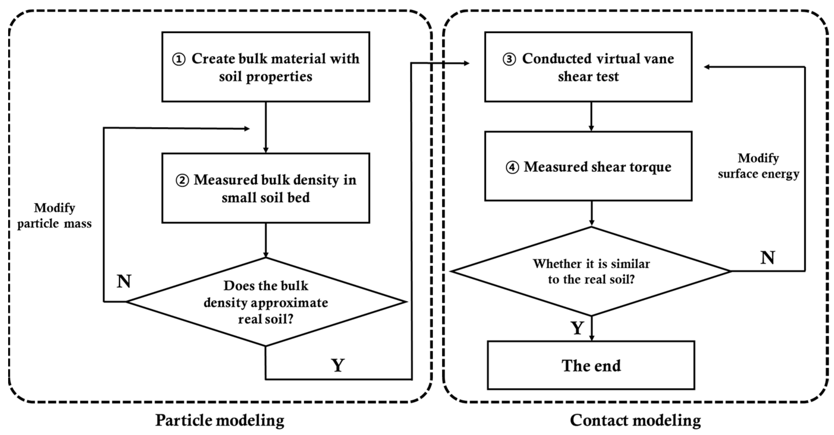
Modeling the virtual soil environment for simulation can be broadly divided into particle modeling and contact modeling. The modeling process proceeded as shown in Figure 2.
The first step in conducting a DEM simulation is to model the particles. Modeling soil particles requires entering parameters such as solid density, Poisson’s ratio, shear modulus, Young’s modulus, and friction coefficient for both soil and steel. Table 1 shows the major particle model parameters in the DEM software (EDEM, 2022, Altair, Troy, MI, USA). The particle size of the soil was set based on past studies to reduce the simulation time without adversely affecting the prediction accuracy [18]. An increase in particle size leads to an increase in voids, so the process of calibrating the mass of the particles based on the actual measured bulk density was performed. The shear modulus and Young’s modulus, which have a direct and significant impact on the draft force, were set based on measured values from field properties experiments. In prior work, Wang et al. [11] investigated subsoiler interaction with soil using DEM and they made a clear distinction between the friction coefficients of ploughed soil and soil beneath the subsoiler when selecting modeling parameters. In this study, the parameters used in Wang et al.’s study were selected to reflect the change in soil properties with depth. The restitution coefficients for soil–soil and soil–steel were selected from values widely used in DEM studies [31,32].
The second step in conducting a DEM simulation is contact modeling. EDEM (EDEM, 2022, Altair, Troy, MI, USA) provides several contact models to reproduce various particle-to-particle contact behaviors. Soil with clay content exhibits a greater capacity for retaining water when compared to sandy soil [33]. This enhanced water retention capability creates a conducive environment for the flourishing of crops. Consequently, it is common to find clay-rich agricultural soils in Korea. This study employed the EEPA contact model to simulate the compressibility and stickiness of agricultural soil. The EEPA contact model is organized into various equations for numerical analysis. The vertical normal force of the EEPA model is given by Equation (2)
F n = f h y s + f n d u ,
where F n is the total contact normal force, f h y s is the hysteretic spring stiffness, f n d is the damping force, and u is the unit normal vector pointing to the center of the particle at the contact point.
f s y s = f 0 + k 1 δ n        i f    k 2 ( δ n δ p n )     k 1 δ n f 0 + k 2 ( δ n δ p n )        i f    k 1 δ n > k a d h δ x f 0 k a d h δ x        i f    k a d h δ x > k 2 ( δ n δ p n )
where f 0 is the initial contact normal force, δ n is the initial overlap, k a d h is the adhesive stiffness, and δ x is the overlap due to adhesive force.
f n d = 2 5 6 β N L   K n m v n
K n = 2 E R δ n
β N L = ln e ln e 2 + π 2
where β N L is the coefficient of the normal dashpot in the nonlinear model, K n is the Hertzian stiffness, m is the equivalent mass of the particle, and e is the user-defined restoration factor in the simulation.
Additionally, the contact tangential force ( F t ) was obtained from Equation (7):
F t = f t s   + f d s  
where f t s is the tangential spring force and f t d is the tangential damping force.
f t s = f t s ( n 1 ) + f t s
f t s = k t δ t
k t = ζ t m 8 G R δ n
f t d = 2 5 6 β N L k t m v t r
β t = 4 m k t 1 + ( π l n e ) 2
where f t s ( n 1 ) is the tangential spring force at the previous time step, Δ f t s is the increment in the tangential force, k t is the tangential normal stiffness, δ t is the tangential displacement, ζ t m is the tangential stiffness multiplier, G is the equivalent shear modulus, R is the equivalent radius, v t is the relative tangential velocity between the two particles, and β t is the linear tangential dashpot coefficient, which depend on the tangential stiffness.
τ i = μ t f h y s R i ω i
Finally, the rolling friction torque τ i was obtained from Equation (9), μ t is the rolling friction, R i is the distance from the contact point to the center of the particle, and ω i is the vector of the unit angular velocity of the particle at the contact point. Equations (2)–(13), used for particle force calculations in EDEM, show that the contact force, which consists of normal and tangential forces, is a function of the particle mass, particle overlap, particle size, Young’s modulus, shear modulus, friction coefficient, and restitution coefficient.
Table 2 presents the key input parameters for the EEPA contact model. In this paper, the input parameters were determined by referring to a soil model with compressibility and adhesion from the Soil Starter Pack provided by DEM software (EDEM, 2022, Altair, Troy, MI, USA). The surface energy was calibrated with a virtual simulation using a ring-type vane shear tester to set the value. For cohesionless soils, the calibration is most often performed with a repose angle experiment. Cohesive soils sometimes exhibit non-flowing characteristics in certain areas. Hence, when calibrating cohesive soils, relying on vane shear test outcomes and comparisons proves more suitable than utilizing the repose angle for calibration. Repeated calibration through virtual vane shear tests was conducted for every soil layer to accurately anticipate the loads induced by tillage activities.

2.3. Design a Working Load Measurement System

2.3.1. Tractor-Implement System

A 42 kW tractor (TX58, TYM, Iksan, Republic of Korea) was selected for this study considering the tillage load. Table 3 shows the specific specifications of the tractors utilized. Moldboard plows are commonly used in soil mechanization research due to their high working stability and soil resistance. In the field experiment, a six-row moldboard plow (WJSP-6S, Woongjin, Gimje, Republic of Korea) with a maximum working depth of 200 mm was used to perform the tillage test. The detailed specifications of the machine are presented in Table 4. The moldboard plow was reverse engineered in a 1:1 ratio using a 3D scanner for the virtual draft force prediction test.

2.3.2. Working Load Measurement System

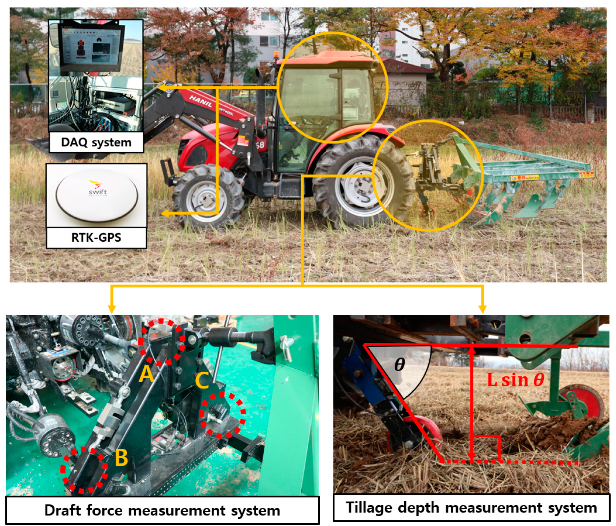
The load generated during tillage operations using a moldboard plow is strongly influenced by tillage depth and travel speed. For a comparative analysis of the effects of soil properties, it is requisite to verify the draft force at a constant tillage depth and travel speed with a device that accurately measures tillage depth and travel speed. The working load measurement system consists of a draft force measurement part, a tillage depth measurement part, and a real-time kinematic global positioning system (RTK-GPS) Mini Survey Antenna GPS1000, Swift Navigation, San Francisco, CA, USA). Figure 3 illustrates the load measurement system along with the installation positions of each measurement component. The part of draft force measurement consisted of a triangular jig with load cells (UU-T2, DACELL, Cheongju, Republic of Korea) to measure the draft force. The draft force ( D ) was obtained as the sum of the loads measured on the three load cells that measure tangential forces ( F A ,   F B ,   F C ).
D = F A + F B + F C
The segment dedicated to tillage depth measurement facilitates the real-time tracking of the moldboard plow’s vertical penetration depth that was achieved by affixing a custom-designed jig, housing an inclinometer (IS2MA090-U-BL, GEMACsensors, Chemnitz, Germany), at the base of the draft force measurement system [5].
d = L   sin θ 1 L   sin θ 2
where d is the tillage depth (cm), L is the length of the lower link of tillage depth measurement system (cm), θ 1 is the initial angle of the lower link measured using the inclination sensor when tillage depth is zero (deg), and θ 2 is the angle of the lower link measured using the inclination sensor when tillage depth occurs (deg).
The RTK-GPS is designed to attach to the tractor’s center of gravity and measure the speed at which it is reduced by slip during tillage operations. The data acquisition system, Dewesoft X (Dewesoft 3X, Dewesoft, Trbovlje, Slovenia), was employed for concurrent field data measurements, operating at a sampling frequency of 1 kHz.

2.4. Field Experimental Design

The predicted draft force from the DEM simulation was compared to field tests to demonstrate its accuracy. Load measurement tests were performed on two fields in different locations to compare the draft force due to differences in soil properties. Field A was located at 37°00′44.4″ N and 126°30′20.4″ E and Field B was located at 37°93′67.2″ N and 127°78′20.6″ E. The tillage operation was performed by speeding the M3 gear (theoretical speed is 7.9 km/h) in four-wheel drive mode on a 100 m straight course with a moldboard plow. The measuring tractor’s results from each field, including the travel speed, tillage depth, and draft force, were recorded across three drives and subsequently organized in ascending order based on tillage depth.

2.5. Theoretical Method for Draft Force Prediction

Typically, the validation of the predicted draft force from tillage operations involves comparing these values against those derived from traditional theoretical calculation methods [34]. For the theoretical calculations, ASAE Standard D.497.4 was used [35]. This method stands out as the simplest and most prevalent due to its reliance on soil texture details, tillage depth, implement geometry, and travel speed to make predictions.
D = F i [ A + B V + C V 2 ] b d
where F i is the dimensionless soil texture adjustment with different values (if soil has fine texture F i = 1, medium texture F i = 0.7, and coarse texture F i = 0.45), A , B , and C are machine-specific parameters determined by the implement type. In the case of moldboard flow, A is 652, B is 0, and C is 5.1.

3. Results

3.1. Result of Soil Properties Measurement

The results of the soil’s physical and mechanical properties measured in the field according to the soil layer are presented in Table 5.
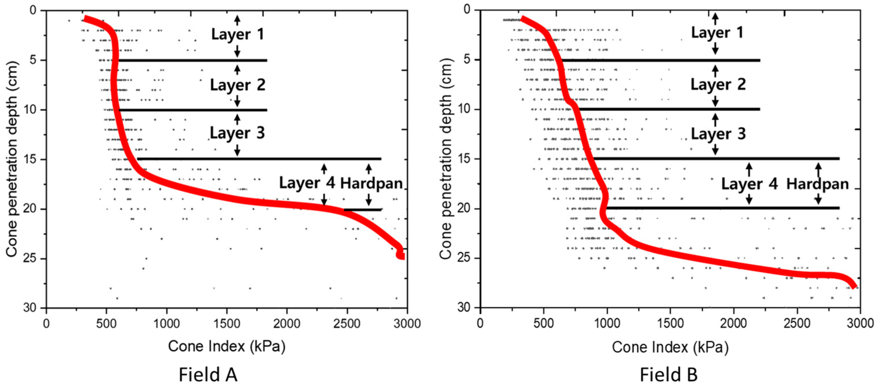
Atterberg limits testing showed that the plastic and liquid limits for Field A were 21.1 ± 1.55% and 34.59 ± 0.81%, respectively, and the plastic and liquid limits for Field B were 19.62 ± 1.22% and 32.31 ± 0.64%. The contact modeling parameters were selected based on the assumption that all soil layers were classified as plastic, which has a similar behavior to the compressible sticky model in the soil starter pack of DEM software (EDEM, 2022, Altair, Troy, MI, USA). A soil particle analysis revealed that Field A exhibited a loam texture composed of 40% sand, 48% silt, and 12% clay, while Field B demonstrated a clay loam texture comprising 40% sand, 28% silt, and 32% clay. The shear strength obtained based on the vane shear torque increased with depth, with Field A increasing by about 1.67 times to 25.19 kPa at Layer 1 and 42.25 kPa at Layer 4, and Field B increasing by about 1.43 times to 65.32 kPa at Layer 1 and 93.10 kPa at Layer 4. Identifying the hardpan layer’s formation site is crucial, as tillage operations aim to disrupt this layer. Figure 4 shows the results of the cone penetration test for Field A and Field B. For the cone penetration test in Field A, the cone index is 491.5, 586.8, 706.4, and 2008.9 kPa, in the order of the layers. The cone index for field B is 548.96, 731.81, 824.75, and 1090.59 kPa, in the order of each layer. For both Field A and Field B, the cone index increases from Layer 3 to Layer 4 by 64.8% and 24.4%, respectively, indicating that the hardpan is located in Layer 4.

3.2. Soil Modeling and Calibration Using DEM

Considering the computational power of the computer, a particle size of a 5 mm radius was selected for the soil modeling. The soil modeled using the discrete element method had more voids than the real soil due to the larger particle size. Therefore, the mass of the particles was calibrated based on the measured bulk density for a realistic draft force prediction. Soil particles were produced within a small soil bin (700 mm × 700 mm × 120 mm) and the total number of particles generated was 20,684. The calibration results are shown in Table 6.
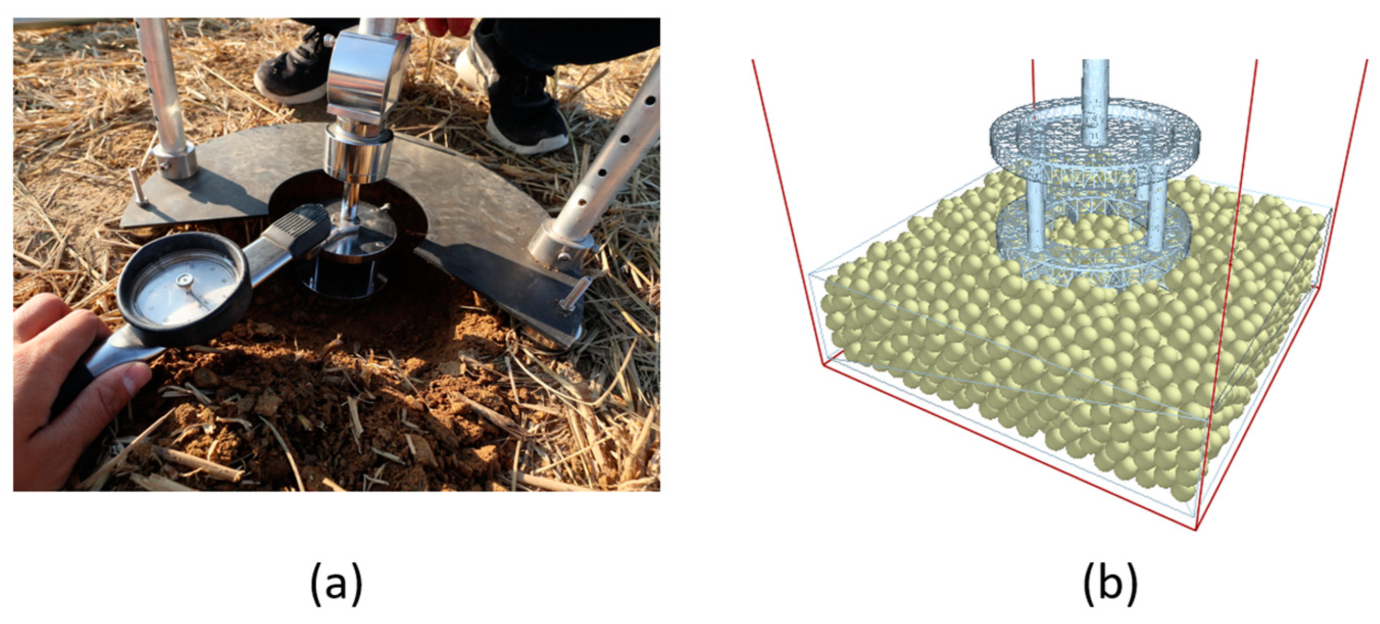
Following the bulk density calibration, the interparticle surface energy was calibrated based on the shear torque obtained from the vane shear test. The vane shear tester was modeled as a CAD step file, as shown in Figure 5, and imported into DEM software (EDEM, 2022, Altair, Troy, MI, USA) to measure the shear torque generated by rotating the vane blades at the same angular speed as the field test. The generated particles were standardized with a radius of 5 mm, mirroring the simulation used for predicting draft force. The shear torque was measured by setting the vane shear tester to penetrate only the vane part to minimize the impact of vertical loading on the measurement. The surface energy values calibrated using shear torque are shown in Table 7. The shear strength error in Field A ranged from 8.51% to 54.9%, and the calibration process reduced the error by 0.16% to 0.89%. In the calibration process for Field A, the input surface energy values were 130, 150, 260, and 330 J/m2 allocated to Layer 1, Layer 2, Layer 3, and Layer 4. For Field B, the error in the shear strength ranged from 9.4% to 39.53%, and the calibration process reduced the error from 0.52% to 1.35%. In the calibration of Field B, the input surface energy values allocated to Layer 1, Layer 2, Layer 3, and Layer 4 were 100, 300, 500, and 900 J/m2 respectively.

3.3. Prediction of Draft Force Based on DEM Simulations

3.3.1. Results of Draft Force Measurements from Actual Field Tests

The actual field tests were conducted three times with the gear selection of the M3 for each field following the draft force measurement procedure. Table 8 shows travel speed and draft force for each tillage depth. The target tillage depth was 15–20 cm, and the average tillage depth was 16.28 cm in Field A and 16.9 cm in Field B. The actual travel speed measured through RTK-GPS was reduced by slip, showing Field A at 5.63 k m / h and Field B at 5.43 k m / h in gear M3. In order to determine the difference in draft force based on the soil properties, it was necessary to uniformize the tillage depth, which has a large impact on the draft force. Based on the tillage depth, the most data were recorded at 16–17 cm and the draft force was averaged at that depth. The results showed that the measured draft force was 12.38 kN in Field A and 14.79 kN in Field B.

3.3.2. Creating a Virtual Soil Bed for Simulation

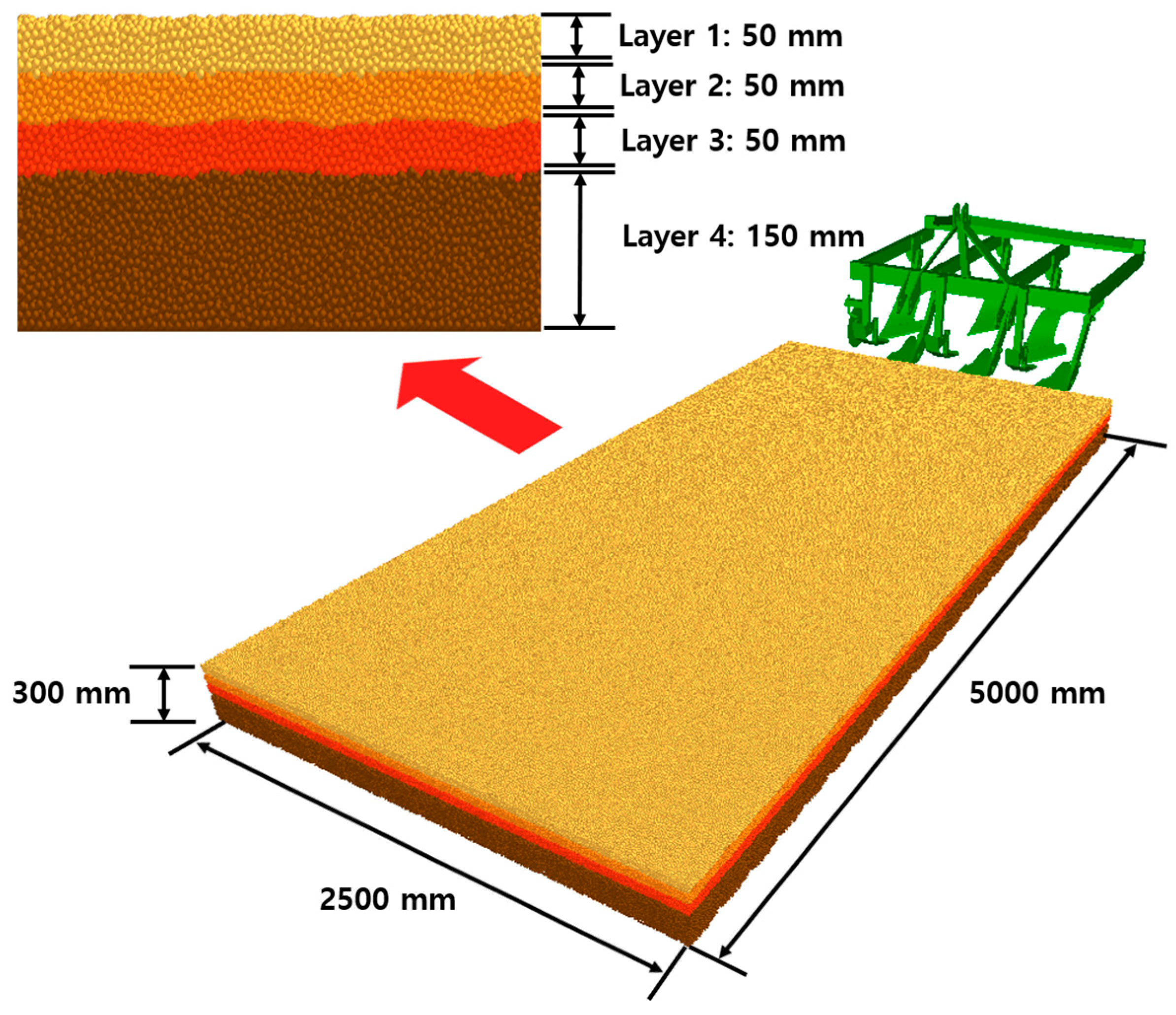
Figure 6 shows a large soil bed that represents the properties of the soil measured in this study. Considering the 1:1 ratio in full-scale moldboard plow geometry and the target tillage depth, the large soil bed size was set to 5000 mm × 2500 mm× 300 mm (length × width × depth) to minimize the interaction between the walls and the particles. The height of each soil layer in the virtual large soil bed was set to 50 mm for Layers 1, 2, and 3 and 150 mm for Layer 4. The total number of particles in the large soil bed was 4,004,939.
The simulation time was 3.2 s to ensure that the moldboard plow was sufficiently penetrated to represent a constant working load. The tillage depth in the simulation was set to 16.5 cm to compare with the actual field test conducted for the purpose of breaking the hardpan layer.

3.3.3. Accuracy Verification of DEM Simulation for Draft Force Prediction

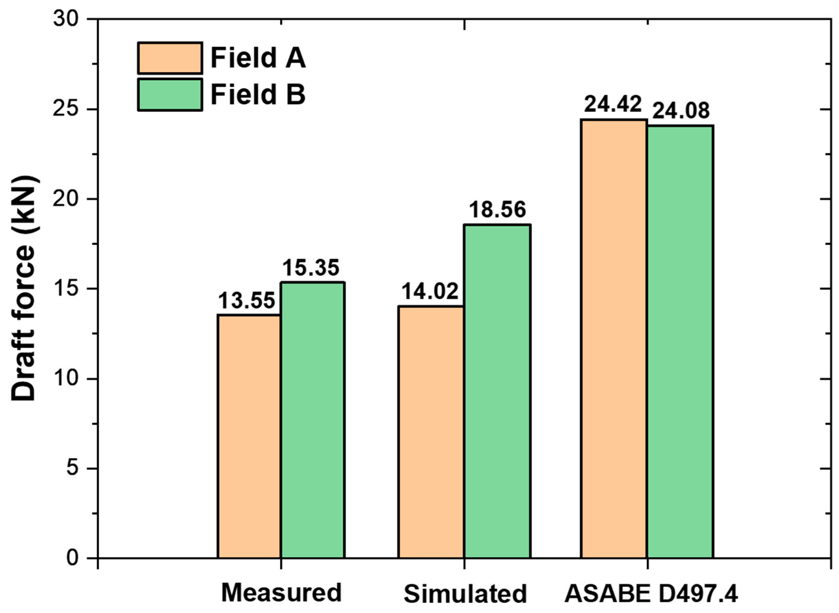
Draft force is a force generated in the same axis as the working direction when the implement is towed by a tractor. To predict the draft force in this study, the total force generated in the Y-axis, the working direction, was analyzed through EDEM (EDEM, 2022, Altair, Troy, MI, USA). Then, the accuracy of the predicted draft force was demonstrated by comparing it to measured values from actual field experiments and to values obtained from the traditional theoretical method. As shown in Table 9, the simulation results show that Field A has a predicted draft force of 14.02 kN and Field B has a predicted draft force of 18.56 kN. The predicted draft forces obtained through the theoretical calculation method are 24.42 kN in Field A and 24.08 kN in Field B. Comparing the draft force measured in the actual field test to the draft force predicted by the simulation, the error for Field A is 13.25% and the error for Field B is 25.49%. The draft force predicted by the theoretical calculation method was 24.42 kN in Field A and 24.08 kN in Field B. Figure 7 shows a graph of the measured draft force from an actual field trial and predicted draft force based on simulation. Savitsky–Golay has the advantage of preserving the shape of the peaks when smoothing [36], so the graph of the draft force recorded in the form of a waveform was fitted with the Savitsky–Golay method. Figure 8 shows a comparison of Field A and Field B, which includes the actual measured draft force, the draft force predicted by the DEM simulation, and the values obtained using traditional theoretical methods. The actual measured draft force was 13.28% higher in Field B than in Field A, while the DEM simulation predicted that the draft force in Field B was 32.38% higher than that in Field A. Despite the errors, the increasing trend of the draft force could be demonstrated through the discrete element method.

4. Discussion

In this study, a procedure for measuring soil properties was established, and property measurement tests were conducted at different depths of the soil in two cohesive fields with different properties. Measured properties include soil texture, moisture content, bulk density, shear strength, cone index, plastic limit, and liquid limit. First, the soil texture of the two fields was determined, with Field A as loam and Field B as clay loam. To determine the difference in draft force based on the properties of the working environment, the cone index of the soil was first compared. The cone index is one indicator of soil compaction, and past research has shown that the cone index is proportional to the workload of a tractor [26]. Compared to Field A, Field B was 1.52 times higher in Layer 1, 1.58 times higher in Layer 2, and 1.62 times higher in Layer 3, while in Layer 4, Field A was 1.84 times higher than Field B. In terms of shear strength, Field B measured higher than Field A in all soil layers: 2.59 times in Layer 1, 2.21 times in Layer 2, 2.19 times in Layer 3, and 2.2 times in Layer 4. For moisture content, Field A had a higher measured moisture content in all layers compared to Field B: 1.21 times at Layer 1, 1.44 times at Layer 2, 1.28 times at Layer 3, and 1.2 times at Layer 4. Rashidi et al. [37] reported that the draft force was the highest at 484 kgf in soil with 11.27% moisture content and the lowest was at 427 kgf in soil with 22.87% moisture content. In addition, S.A. Al-Suhaibani et al. [38] confirmed that the draft force decreases as the moisture content increases in soil at 5.08%, 5.14%, and 6.82%. Based on these past studies, for the two fields that were found to be plastic state by the Atterberg limit test, it can be assumed that the lower moisture content in Field B experienced more draft force. In the actual field test, the measured draft force was 12.38 kN in Field A and 14.79 kN in Field B, with Field B being 19.47% higher than Field A. Based on these results, the analysis of soil properties for draft force prediction should be treated comprehensively, and it is difficult to relate only one factor to draft force.
To reflect the properties of the measured soil in the particle modeling, two steps of calibration were performed. Since this process results in more voids than in real soil, the mass of the particles was calibrated based on the bulk density. As a result, the error was reduced to a range of 0.005–0.79%. In addition, unlike cohesionless soil, the cohesive soil modeling was calibrated for surface energy by performing a vane shear test rather than an angle of repose test. As a result, the virtual test closely reproduced the measured shear torque with an error from 0.16 to 1.35%. Despite calibrating the values of bulk density and shear torque to within 1.5% of each other, there was a prediction error of 13.25% for Field A and 25.49% for Field B. This indicates the need for more precise soil property measurements for modeling parameters that were not addressed, such as the coefficient of restitution and plasticity ratio. The fact that more prediction errors occurred in Field B compared to Field A is also an important discussion point. In this study, in the process of reflecting the measured soil properties into the particle modeling, a virtual vane shear test was performed to calibrate the surface energy based on the shear torque. As a result, Field A showed an error in shear torque of less than 1%, while Field B was calibrated with an error of up to 1.35%. It can be seen that an error in the calibration step led to more error in predicting the draft force.
The DEM-simulation-based predicted draft force was 14.02 kN in Field A and 18.56 kN in Field B, differences of 13.25% and 25.49%, respectively, when compared to the actual field test. Compared to the traditional theoretical calculation method, the DEM-simulation-based draft force prediction was 84% more accurate for Field A and 37.32% more accurate for Field B. Since the existing theoretical calculation method comprehensively classified soil texture into three categories (fine, medium, and coarse) and did not reflect other soil properties except soil texture, it could not show the difference in predicted draft force under the same type of implement and almost similar working conditions (tillage depth and travel speed, etc.). On the other hand, DEM-simulation-based draft force predictions were significant even under similar operating conditions (same tillage depth and similar travel speed), reflecting the soil properties that affect draft force.

5. Conclusions

In this study, a draft force prediction model using DEM was developed to verify the effect of soil properties on draft force through simulation. The soil textures of the two fields were loam and clay loam, and the difference in draft force due to the difference in the physical properties of the two fields could be seen. The developed prediction model was also verified by comparing the actual field experiment with the existing theoretical calculation method. Soil property measurements were conducted at each depth in two fields with different physical properties. The Atterberg limit test revealed that both soils were cohesive soil in a plastic state. Past studies have shown that, the higher the shear strength and cone index, and the lower the moisture content in a certain section, the higher the draft force. However, Field B had a higher shear strength, lower moisture content, and lower cone index compared to Field A. Therefore, it is difficult to relate to a single factor when predicting the draft force, and many factors must be considered together. The precision of the predicted draft force from DEM simulations was confirmed by juxtaposing it with the measured draft force obtained from real-field experiments. In Field A, the draft force prediction from DEM simulations demonstrated an accuracy rate of 86.75%, while, in Field B, it reached 74.51%. The process of calibrating the surface energy based on shear torque resulted in more errors in Field B than in Field A, which led to a larger error in the draft force prediction. In future research, it is recommended to further study the modeling of various agricultural soil environments to improve the accuracy of design load prediction for soil–machine systems. The developed DEM-based draft force prediction model is up to 84% more accurate than the existing theoretical method by ASABE D497.4. This demonstrated the importance of reflecting the physical and mechanical characteristics of the working environment when assessing the performance of agricultural machinery. Performance evaluations of soil tillage machines include not only the workload, but also the degree of soil crushing and the flow of soil to invert and properly drain the soil. Future research should focus on enhancing the initial prediction accuracy of workload by employing precise soil property measurements based on modal modeling parameters. Furthermore, it is anticipated that the acceleration of simulation-based design optimization will be achieved through the establishment of a comprehensive database encompassing diverse soil environments. This will enable a more thorough study of load predictions for various types of working machines beyond moldboard plow. For virtual simulation-based performance evaluations, it is important to obtain a database for defining various farming environments and analyzing loads. The results of this study are expected to be used as indicators of soil–tool interaction in future soil–tractor and soil–tire interaction studies for agricultural operations.

Author Contributions

Conceptualization, Y.-S.K. and Y.-J.K.; methodology, Y.-S.K. and W.-S.K.; software, B.-M.B. and T.-J.K.; validation, Y.-S.K. and B.-M.B.; formal analysis, Y.-S.K. and B.-M.B.; investigation, Y.-J.K. and S.-D.L.; data curation, Y.-S.K. and B.-M.B.; writing original, B.-M.B.; writing—review and editing, Y.-S.K. and W.-S.K.; supervision, Y.-J.K. and S.-D.L.; project administration, Y.-J.K. and S.-D.L.; funding acquisition, Y.-J.K. and S.-D.L. All authors have read and agreed to the published version of the manuscript.

Funding

This work was supported by the Industrial Strategic Technology Development Program (20014649, Development of intelligent technology and standard integrated controller for tractor attached implement) funded By the Ministry of Trade, Industry & Energy (MOTIE, Republic of Korea).

Institutional Review Board Statement

Not applicable.

Data Availability Statement

Data are contained within the article.

Conflicts of Interest

The authors declare no conflict of interest.

References

  1. Mahatale, Y.V.; Tathod, D.V.; Chavan, V.K. Performance of Reversible Mold Board Plow. In Emerging Technologies in Agricultural Engineering; Apple Academic Press: Palm Bay, FL, USA, 2017; pp. 137–163. [Google Scholar]
  2. Kim, W.-S.; Kim, Y.-J.; Park, S.-U.; Nam, K.-C.; Choi, C.-H. Analysis of Traction Performance for an Agricultural Tractor According to Soil Moisture Content during Plow Tillage. In Proceedings of the 2019 ASABE Annual International Meeting, Boston, MA, USA, 7–9 July 2019; pp. 2–7. [Google Scholar]
  3. Raper, R.L. Force requirements and soil disruption of straight and bentleg subsoilers for conservation tillage systems. Appl. Eng. Agric. 2005, 21, 787–794. [Google Scholar] [CrossRef]
  4. Kim, Y.S.; Kim, W.S.; Baek, S.Y.; Baek, S.M.; Kim, Y.J.; Lee, S.D.; Kim, Y.J. Analysis of Tillage Depth and Gear Selection for Mechanical Load and Fuel Efficiency of an Agricultural Tractor Using an Agricultural Field Measuring System. Sensors 2020, 20, 2450. [Google Scholar] [CrossRef] [PubMed]
  5. Kim, Y.S.; Kim, T.J.; Kim, Y.J.; Lee, S.D.; Park, S.U.; Kim, W.S. Development of a Real-Time Tillage Depth Measurement System for Agricultural Tractors: Application to the Effect Analysis of Tillage Depth on Draft Force during Plow Tillage. Sensors 2020, 20, 912. [Google Scholar] [CrossRef] [PubMed]
  6. Aikins, K.A.; Ucgul, M.; Barr, J.B.; Awuah, E.; Antille, D.L.; Jensen, T.A.; Desbiolles, J.M.A. Review of Discrete Element Method Simulations of Soil Tillage and Furrow Opening. Agriculture 2023, 13, 541. [Google Scholar] [CrossRef]
  7. Fielke, J.M. Finite Element Modelling of the Interaction of the Cutting Edge of Tillage Implements with Soil. J. Agric. Eng. Res. 1999, 74, 91–101. [Google Scholar] [CrossRef]
  8. Ucgul, M.; Saunders, C.; Fielke, J.M. Comparison of the Discrete Element and Finite Element Methods to Model the Interaction of Soil and Tool Cutting Edge. Biosyst. Eng. 2018, 169, 199–208. [Google Scholar] [CrossRef]
  9. Bentaher, H.; Ibrahmi, A.; Hamza, E.; Hbaieb, M.; Kantchev, G.; Maalej, A.; Arnold, W. Finite Element Simulation of Moldboard–Soil Interaction. Soil Tillage Res. 2013, 134, 11–16. [Google Scholar] [CrossRef]
  10. Ibrahmi, A.; Bentaher, H.; Hbaieb, M.; Maalej, A.; Mouazen, A.M. Study the Effect of Tool Geometry and Operational Conditions on Mouldboard Plough Forces and Energy Requirement: Part 1. Finite Element Simulation. Comput. Electron. Agric. 2015, 117, 258–267. [Google Scholar] [CrossRef]
  11. Wang, X.; Zhang, S.; Pan, H.; Zheng, Z.; Huang, Y.; Zhu, R. Effect of Soil Particle Size on Soil-Subsoiler Interactions Using the Discrete Element Method Simulations. Biosyst. Eng. 2019, 182, 138–150. [Google Scholar] [CrossRef]
  12. Obermayr, M.; Dressler, K.; Vrettos, C.; Eberhard, P. Prediction of Draft Forces in Cohesionless Soil with the Discrete Element Method. J. Terramech. 2011, 48, 347–358. [Google Scholar] [CrossRef]
  13. Ucgul, M.; Fielke, J.M.; Saunders, C. Three-Dimensional Discrete Element Modelling (DEM) of Tillage: Accounting for Soil Cohesion and Adhesion. Biosyst. Eng. 2015, 129, 298–306. [Google Scholar] [CrossRef]
  14. Tekeste, M.Z.; Balvanz, L.R.; Hatfield, J.L.; Ghorbani, S. Discrete Element Modeling of Cultivator Sweep-to-Soil Interaction: Worn and Hardened Edges Effects on Soil-Tool Forces and Soil Flow. J. Terramech. 2019, 82, 1–11. [Google Scholar] [CrossRef]
  15. Bravo, E.L.; Tijskens, E.; Suárez, M.H.; Gonzalez Cueto, O.; Ramon, H. Prediction Model for Non-Inversion Soil Tillage Implemented on Discrete Element Method. Comput. Electron. Agric. 2014, 106, 120–127. [Google Scholar] [CrossRef]
  16. DEM Solutions Ltd. Theory Reference Guide, Version 2.6; DEM Solutions Ltd.: Edinburgh, UK, 2014. [Google Scholar]
  17. Morrisey, J.P.; Thakur, S.C.; Ooi, J.Y. EDEM Contact Model: Adhesive Elasto-Plastic Model. Granul. Matter 2014, 16, 383–400. [Google Scholar]
  18. Kim, Y.S.; Siddique, M.A.A.; Kim, W.S.; Kim, Y.J.; Lee, S.D.; Lee, D.K.; Hwang, S.J.; Nam, J.S.; Park, S.U.; Lim, R.G. DEM Simulation for Draft Force Prediction of Moldboard Plow According to the Tillage Depth in Cohesive Soil. Comput. Electron. Agric. 2021, 189, 106368. [Google Scholar] [CrossRef]
  19. Tan, K.H. Soil Sampling, Preparation, and Analysis; CRC Press: New York, NY, USA, 1995; ISBN 0-8247-9675-6. [Google Scholar]
  20. O’Kelly, B.C.; Sivakumar, V. Water Content Determinations for Peat and Other Organic Soils Using the Oven-Drying Method. Dry. Technol. 2014, 32, 631–643. [Google Scholar] [CrossRef]
  21. Klute, A.; Bradford, J.M.; Gupta, S.C. Compressibility. Methods Soil Anal. Part 1—Physical Mineral. Methods. Soil Sci. Soc. Am. Am. Soc. Agron. 1986, 377–382. [Google Scholar] [CrossRef]
  22. Ditzler, C.; Scheffe, K.; Monger, H.C. USDA Handbook 18; Government Printing Office: Washington, DC, USA, 2017. [Google Scholar]
  23. Thien, S.J. A Flow Diagram for Teaching Texture-by-Feel Analysis. J. Agron. Educ. 1979, 8, 54–55. [Google Scholar] [CrossRef]
  24. Ibrahim, N.M.; Rahim, N.L.; Amat, R.C.; Salehuddin, S.; Ariffin, N.A. Determination of Plasticity Index and Compression Index of Soil at Perlis. APCBEE Procedia 2012, 4, 94–98. [Google Scholar] [CrossRef]
  25. D4318-10; Test Methods for Liquid Limit, Plastic Limit, and Plasticity Index of Soils (D4318-10), Report. ASTM International Standard: West Conshohocken, PA, USA, 2010.
  26. Kim, W.S.; Kim, Y.J.; Baek, S.M.; Baek, S.Y.; Moon, S.P.; Lee, N.G.; Kim, T.J.; Siddique, A.A.; Jeon, H.H.; Kim, Y.S. Effect of the Cone Index on the Work Load of the Agricultural Tractor. J. Drive Control 2020, 17, 9–18. [Google Scholar] [CrossRef]
  27. Benjamin, J.G.; Cruse, R.M. Tillage Effects on Shear Strength and Bulk Density of Soil Aggregates. Soil Tillage Res. 1987, 9, 255–263. [Google Scholar] [CrossRef]
  28. ASABE Standards EP542; Procedure for Using and Reporting Data Obtained with the Soil Cone Penetrometer. ASAE: St. Joseph, MI, USA, 2009; Volume 1999.
  29. ASABE Standards S313.3; Soil Cone Penetrometer. ASAE: St. Joseph, MI, USA, 2005; Volume 1999.
  30. Srivastava, A.K.; Goering, C.E.; Rohrbach, R.P.; Buckmaster, D.R. Engineering Principles of Agricultural Machines, 2nd ed.; The American Society of Agricultural and Biological Engineers: St. Joseph, MI, USA, 2006. [Google Scholar]
  31. Hang, C.; Gao, X.; Yuan, M.; Huang, Y.; Zhu, R. Discrete Element Simulations and Experiments of Soil Disturbance as Affected by the Tine Spacing of Subsoiler. Biosyst. Eng. 2018, 168, 73–82. [Google Scholar] [CrossRef]
  32. Saunders, C.; Ucgul, M.; Godwin, R.J. Discrete Element Method (DEM) Simulation to Improve Performance of a Mouldboard Skimmer. Soil Tillage Res. 2021, 205, 104764. [Google Scholar] [CrossRef]
  33. Bolotov, A.G.; Shein, E.V.; Makarychev, S.V. Water Retention Capacity of Soils in the Altai Region. Eurasian Soil Sci. 2019, 52, 187–192. [Google Scholar] [CrossRef]
  34. Ahmadi, I. Development and Assessment of a Draft Force Calculator for Disk Plow Using the Laws of Classical Mechanics. Soil Tillage Res. 2016, 163, 32–40. [Google Scholar] [CrossRef]
  35. Palmer, R.A. American Society of Agricultural Engineers. Science 1953, 118, 3. [Google Scholar] [CrossRef]
  36. Savitzky, A.; Golay, M.J.E. Smoothing and Differentiation of Data. Anal. Chem. 1964, 36, 1627–1639. [Google Scholar] [CrossRef]
  37. Ranjbar, I.; Rashidi, M.; Lehmali, H.F.; Mirmoradi, M.; Abdolalizadeh, E. Modeling of Double Action Disc Harrow Draft Force Based on Tillage Depth and Forward Speed. Middle East J. Sci. Res. 2013, 17, 1061–1067. [Google Scholar]
  38. Al-Suhaibani, S.A.M.F.; Wahby, A.M.; Aboukarima, I.S.T. Study on the Effect of Soil Moisture Content and Plowing Speed on Draft Requirements of a Moldboard Plow. J. Adv. Agric. 2015, 4, 477–486. [Google Scholar]
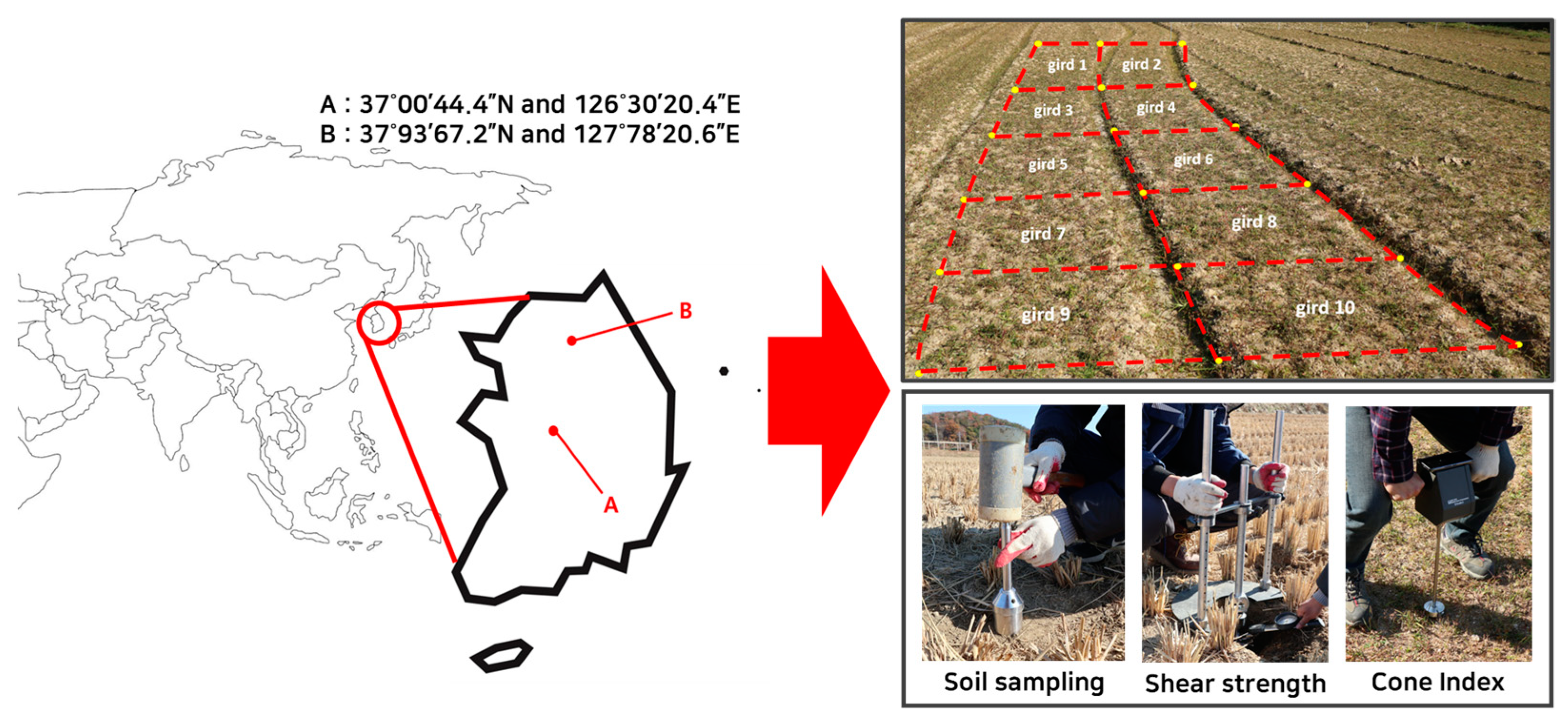
Figure 1. Location of test fields and uniformed grid sampling methods.
Agriculture 13 02205 g001
Figure 2. Modeling Procedures for Virtual Soil Environments.
Agriculture 13 02205 g002
Figure 3. Configuration of field load measurement system.
Agriculture 13 02205 g003
Figure 4. Results of cone penetration test.
Agriculture 13 02205 g004
Figure 5. Calibration of shear torque using vane shear test: (a) field experiments and (b) EDEM simulation.
Agriculture 13 02205 g005
Figure 6. Virtual large soil bed made based on measured soil properties by soil layer.
Agriculture 13 02205 g006
Figure 7. Comparison of draft force between actual field test and DEM simulation at 16.5 cm tillage depth. (a) Field A and (b) Field B.
Agriculture 13 02205 g007
Figure 8. Comparison of draft force between Field A and Field B.
Agriculture 13 02205 g008
Table 1. Major particle model parameters in EDEM.
PropertiesValue
Particle size of soilRadii 5 mm
Particle mass of soilCalibrated
Shear modulusMeasured
Young’s modulusMeasured
Static friction coefficient of soil–soil0.4
Rolling friction coefficient of plough layer0.58
Rolling friction coefficient of hardpan layer0.25
Static friction coefficient of soil–steel0.24
Rolling friction coefficient of plough layer-steel0.34
Rolling friction coefficient of hardpan layer-steel0.14
Restitution coefficient of soil–soil0.2
Restitution coefficient of soil–steel0.3
Table 2. Major contact model parameters in EDEM.
PropertiesValue
Constant pull-off force0
Surface energyCalibrated
Tensile exponent5
Tangential stiff multiplier0.28571
Slope exponent1.5
Contact plasticity ratio0.75
Table 3. Specifications of the agricultural tractor used in this study.
ItemSpecification
CompanyTYM
ModelTX58
Wheel base (mm)2155
Length × width × height (mm)3695 × 1848 × 2560
EngineRated power (kW)42 @ 2000 rpm
Max torque (Nm)211.8 @ 1600 rpm
Transmission gear selectionMain 4 stage/Sub 6 stage
PTO gear selection1st 540 rpm
2nd 750 rpm
3rd 1000 rpm
Tire (inch)Front 11.2–20
Rear 14.9–30
Maximum travel speed (km/h)33.8
Table 4. Specifications of the moldboard plow used in this study.
ItemSpecification
Product nameWJSP-6S
Manufacturing companyWoongjin
TypeMoldboard plow
Length × width × height (mm)1930 × 1800 × 1235
Rake angle (deg)30.76
Tillage width (mm)270
Share length (mm)360
Share formPointed
Required power (kW)40–52
Maximum tillage depth (mm)Up to 200
Coulter typeSkid jig/Plain coulter with spring
Coulter diameters (mm)340
Number of furrows3
Required travel speed (km/h)5–8
Table 5. Measured on-field soil properties according to soil layer.
FieldPropertiesSoil Layer
Layer 1 (0~5 cm)Layer 2 (5~10 cm)Layer 3 (10~15 cm)Layer 4 (15~20 cm)
ABulk density (g/cm3)1.501.601.721.90
Moisture contents (%)32.2134.2028.7224.23
Cone index (kPa)465.48547.92636.961900.2
Shear strength (kPa)25.1930.8732.9042.25
BBulk density (g/cm3)1.901.911.962.02
Moisture contents (%)26.5623.8122.4920.24
Cone index (kPa)707.56868.441063.162153.64
Shear strength (kPa)65.3268.2472.1493.10
Table 6. Calibration results of bulk density.
FieldSoil LayerProcedureParticle Mass (kg)Bulk Density (kg/m3)Calibration Error (%)
SimulatedMeasured
ALayer 1Initial0.001441538.901496.582.83
Calibrated0.001381508.420.79
Layer 2Initial0.001441559.091597.012.37
Calibrated0.001471597.440.03
Layer 3Initial0.001441557.891715.299.18
Calibrated0.001591714.880.02
Layer 4Initial0.001441565.491904.4617.80
Calibrated0.001751904.810.02
BLayer 1Initial0.001441269.911899.833.16
Calibrated0.001741901.430.09
Layer 2Initial0.001441269.911905.6433.36
Calibrated0.001751912.360.35
Layer 3Initial0.001441905.691955.4835.05
Calibrated0.001791956.070.03
Layer 4Initial0.001441269.912021.5437.18
Calibrated0.001852021.640.005
Table 7. Calibration results for shear torque in small soil bin using field measurements values.
FieldSoil LayerProcedureSurface Energy (j/m2)Shearing Torque (Nm)Calibration Error (%)
SimulatedMeasured
ALayer 1Initial1004.735.178.51
Calibrated1305.130.77
Layer 2Initial1005.116.3319.27
Calibrated1506.320.16
Layer 3Initial1003.816.7543.56
Calibrated2606.690.89
Layer 4Initial1003.918.6754.9
Calibrated3308.640.35
BLayer 1Initial10012.1413.49.4
Calibrated10013.551.19
Layer 2Initial10012.561410.29
Calibrated30013.841.14
Layer 3Initial10011.9314.819.39
Calibrated500151.35
Layer 4Initial10011.5519.139.53
Calibrated90019.20.52
Table 8. Draft force measurement results from actual field experiment.
Field AField B
Tillage Depth
(cm)
Travel Speed
(km/h)
Draft Force
(kN)
Tillage Depth
(cm)
Travel Speed
(km/h)
Draft Force
(kN)
155.89 ± 0.3511.61155.83 ± 0.5113.71
165.85 ± 0.3112.11165.68 ± 0.6514.72
175.77 ± 0.3312.64175.47 ± 0.5914.86
185.62 ± 0.3413.29185.61 ± 0.5115.18
195.41 ± 0.3913.53194.99 ± 0.8017.80
205.25 ± 0.4814.30204.97 ± 0.7116.81
Table 9. Result of draft force predict simulation.
FieldTillage Depth (cm)Travel Speed (km/h)Draft Force (kN)Predicted Error (%)
SimulatedMeasured
A16.55.6314.0212.3813.25
B5.4318.5614.7925.49
Disclaimer/Publisher’s Note: The statements, opinions and data contained in all publications are solely those of the individual author(s) and contributor(s) and not of MDPI and/or the editor(s). MDPI and/or the editor(s) disclaim responsibility for any injury to people or property resulting from any ideas, methods, instructions or products referred to in the content.