Article

Design of an Electronically Controlled Fertilization System for an Air-Assisted Side-Deep Fertilization Machine

1
School of Agricultural Equipment Engineering, Jiangsu University, Zhenjiang 212013, China
2
Key Laboratory of Transplanting Equipment and Technology of Zhejiang Province, Hangzhou 311121, China
3
Jiangsu Zhengchang Group, Changzhou 213300, China
4
Intelligent Equipment Research Center, Beijing Academy of Agriculture and Forestry Sciences, Beijing 100097, China
*
Author to whom correspondence should be addressed.
Agriculture 2023, 13(12), 2210; https://doi.org/10.3390/agriculture13122210
Submission received: 2 November 2023 / Revised: 22 November 2023 / Accepted: 26 November 2023 / Published: 28 November 2023

Abstract

:
The traditional air-assisted side-deep fertilization device has some problems, such as inaccurate control system parameters and poor precision in variable fertilization. It seriously affects the application and popularization of the device. Aiming at the above problems, this paper wanted to realize the precise fertilizer discharge control of an air-assisted side-deep fertilization device. This paper designs an electronically controlled fertilization system based on a PID controller from the past. The system model was constructed in MATLAB, and the mathematical model and transfer function model of a stepper motor, the mathematical model of fertilizer discharge, and the stepper motor rotational speed were established too. In order to improve the accuracy of precise fertilizer discharge control system parameters, the system parameters were optimized based on the particle swarm optimization algorithm and the control system tuner toolbox. We had established a validation test platform to test the performance of a precise fertilizer discharge control system. In the actual experiment, the maximum stability coefficient of variation was 0.91% at the target fertilizer discharge mass level of 350 g/min, and the maximum error of fertilizer discharge was 4.14% at 550 g/min of the target fertilizer discharge mass level. By analyzing the test results of the precise fertilizer discharge control system, the new precise fertilizer discharge control system had good fertilizer discharge stability and could also meet the technical specification for quality evaluation of fertilization machinery (NY/T 1003-2006). This research can improve the fertilizer discharge accuracy of the air-assisted side-deep fertilization control system.

1. Introduction

Agronomists pointed out that adopting reasonable and effective fertilization management methods was the key to increasing rice yield and improving rice quality [1,2]. However, according to the “Research Report on Fertilizer Utilization Efficiency of China’s Three Major Grain Crops” released by the Chinese government, the problems of excessive application of chemical fertilizers, unreasonable application methods, and low utilization efficiency in rice fertilization management in China were very prominent [3]. Moreover, the problems of soil acidification and environmental pollution caused by excessive chemical fertilizer application cannot be ignored [4]. Therefore, while maintaining the sustained high and stable yield of rice, the pressure of reducing the chemical fertilizer application and increasing efficiency in China remained enormous.
Faced with the problems of excessive application of chemical fertilizers, unreasonable application methods, and low utilization efficiency in rice fertilization management in China, agricultural experts have proposed the rice side-deep fertilization management technology. This technology requires fertilization equipment to accurately deliver fertilizers to a depth of 4–5 cm in the mud located 3–5 cm away from the rice seedling root system. Previously verified by agricultural experts, this fertilization technology can reduce fertilizer application while minimizing NH3 volatilization and nitrogen loss, making it a potential alternative to traditional rice surface fertilization methods. Currently, this technology has been listed as one of the “2020 National Ten Major Leading Agricultural Technologies” by the Ministry of Agriculture of China [5], indicating that the rice side-deep fertilization management technology has good prospects for agricultural extension and application.
In order to meet the key equipment requirements for the large-scale promotion and application of rice side-deep fertilization management technology, many scientific researchers and companies have conducted extensive research on side-deep fertilization control system equipment [6,7]. For example, Yang et al. [8] developed a side-deep fertilization device to combine with the sliding-knife furrow opener and the pneumatic ejector for the liquid fertilizer atomizer using side-deep fertilization and liquid fertilizer. According to the requirements of rice planting, Chen et al. [9] developed a synchronous side-deep fertilizing technique based on a precision rice hill-drop drilling technique. According to the agronomic requirements of paddy field fertilizing in Heilongjiang Province and to ensure the efficiency and quality of paddy field side-deep fertilizing apparatus, Wang et al. [10] designed a kind of conical disc and push plate double-row fertilizer apparatus and determined the structural parameters and critical speed. Referring to the agronomic requirements of side-deep fertilization in paddy fields and the structure of the transplanter, Wang et al. [11,12] also designed a side-deep fertilizing device on which it was easy to adjust the amount of fertilizer and prevent blockage and determined the basic structural parameters of the device. At present, mechanical transmission with lower control precision is used in rice side-deep fertilization in agriculture.
In order to improve the working accuracy of the rice side-deep fertilization system, Zuo et al. [13] analyzed the fertilization method of wind delivery and developed the air-blast rice side-deep precision fertilization device. In order to solve the problems of excessive application of fertilizer and the low utilization rate of fertilizer in the process of rice direct-seeding with synchronous fertilizing, Wang et al. [14] developed an electrical drive side-deep hill-drop fertilization system for the precision rice hill-direct-seeding machine. In terms of variable fertilizer application, Yang et al. [15] designed a control system with a variable fertilizer applicator for winter, and the control system adopted PID control technology to ensure accurate use of fertilizer. Liu et al. [16] developed an electronic drive and control system for the measurement of micro-granular fertilizer in a precision planter, and the system was controlled using a closed-loop controller. Pareek et al. [17] used the metamodel based on the Gaussian process and the indoor test data to identify the process of variable-rate fertilization. Cousins and Noble [18] introduced a deep variable-speed liquid fertilizer applicator based on ZigBee technology, and the incremental PID control algorithm was adopted to dynamically adjust the frequency converter to achieve the set liquid fertilizer flow. In variable fertilization, a PID controller with excellent parameters can improve the stability of the control system, but few researchers have carried out in-depth research on the parameters.
For this reason, the model of an electric control fertilization system was studied in combination with the agronomic requirements of implementing side-deep fertilization techniques. A design was created for the air-assisted side-deep fertilization control platform, employing a method that involves using fans to supply air and motors to discharge fertilizer, which facilitated accurate fertilization. The control system model was established for the electric control fertilization system, and the optimal controller parameters were determined using various algorithms. This method has the potential to enhance the evenness and accuracy of electric control fertilization applications.

2. Materials and Methods

2.1. Design of Air-Assisted Side-Deep Fertilization Machine

The air-assisted side-deep fertilization machine uses a fan to deliver granular fertilizer to 3–5 cm on the seedling side, and the fertilization depth is 4–5 cm. The method can extend the fertilizer effect and significantly improve the utilization rate of the fertilizer [19,20]. This paper designs an air-assisted electric fertilization system. In order to improve the stability of the air-assisted side-deep fertilization control system, a simulation modeling analysis was carried out in combination with the established control system platform to obtain the optimal parameters of the control system. On the basis of the simulation modeling, a physical platform was designed [21]. As shown in Figure 1, the overall structure of the air-assisted side-deep fertilization machine mainly includes a conveying fan, wind speed sensor, fertilizer box, support mechanism, Venturi fertilizer apparatus, fertilizer discharge shaft, transmission chain, fertilizer discharge stepper motor, driver, stepper motor controller, terminal controller, furrow opener, and fertilizer pipeline. Among them, the fertilizer discharge stepper motor is connected to the fertilizer discharge shaft through the transmission chain to drive the Venturi fertilizer apparatus to perform fertilizer discharge work and form a precise fertilizer discharge module of the air-assisted side-deep fertilization machine. The conveying fan is connected to the fertilizer pipeline through the wind speed sensor, forming a pneumatic fertilizer conveying module of the air-assisted side-deep fertilization machine. And the wind speed sensor is mainly used to monitor the wind speed changes in the conveying air flow in real-time.
This paper mainly conducted research on the precise control methods of the fertilizer discharge module and developed a precise fertilizer discharge control system for an air-assisted side-deep fertilization machine. Under the working state, the stepper motor controller sets the pulse frequency according to fertilization parameters and data received. The stepper motor controller transmitted the signal to the driver, which controlled the rotation of the fertilizer discharge stepper motor. On the other hand, the encoder of the fertilizer discharge stepper motor collected rotary speed information and fed the pulse signal to the stepper motor controller. The stepper motor controller calculated the real-time stepper motor rotary speed to guide the electronic fertilizer discharge. The precise fertilizer discharge module of the air-assisted side-deep fertilization machine uses the incremental PID control method, and an electric control fertilization closed-loop system based on PID control was designed. In the electric control fertilization closed-loop system, the determination of the control algorithm and control parameters was the premise for ensuring the stability of the system. This paper, through the simulation model and platform test, obtains the best control parameters of electric control fertilization closed-loop systems.

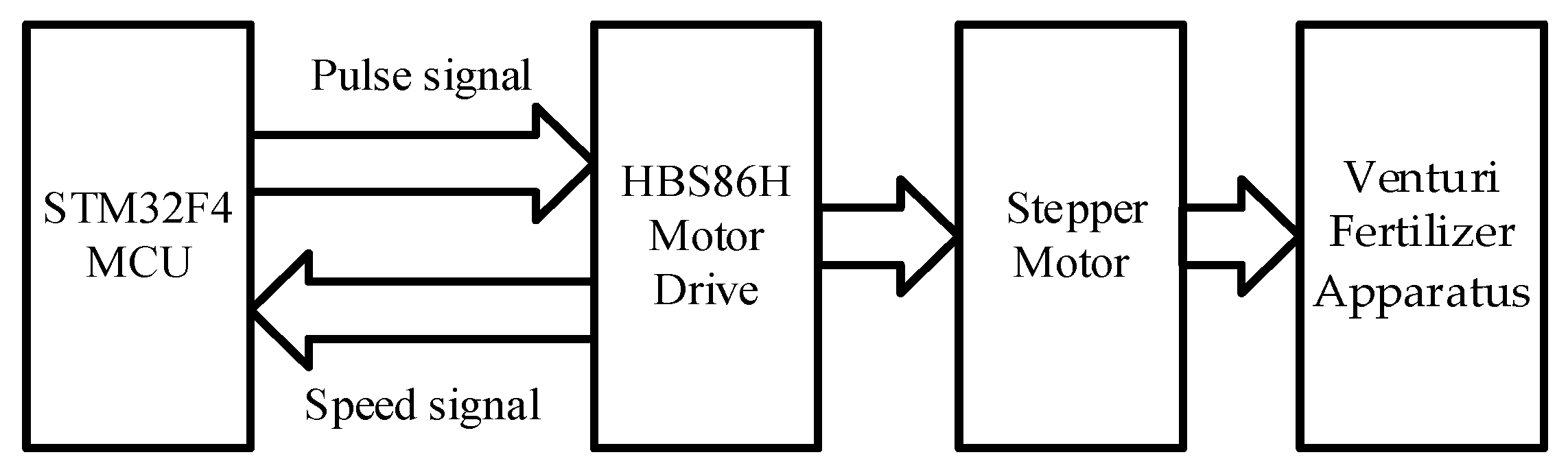
2.2. Electronic Control Hardware of Precise Fertilizer Discharge Module

This research uses the STM32F4 MCU as the core of the stepper motor controller, and the working principle of the precise fertilizer discharge module is shown in Figure 2. The STM32F4 MCU had sufficient pin resources to meet stepper motor controller needs [22]. The stepper motor controller can send pulse signals, direction signals, and enabling signals to the driver. The driver uses a HBS86H motor driver, which could realize the subdivision drive of the stepper motor. The HBS86H motor driver uses a 1000 p/r high-precision optical encoder. Unlike traditional internal microstep drivers, the HBS86H motor driver integrates a high-performance dual-core digital signal processor. And it can perform well under high loads and high-speed conditions without any out-of-step or positioning errors. On the other hand, the HBS86H motor driver can adjust the control current in real-time according to load changes, so it can reduce heat generation and improve usage efficiency [23].
We designed the stepper motor control circuit and rotational speed feedback circuit as shown in Figure 3. And in the design of the electronic control hardware for the precise fertilizer discharge module, the pulse frequency was set at 84 Mkz, the encoder used a 5 V power supply, and the sampling frequency was 50 Hz [24]. The controller used comparison output, the stepper motor rotary speed was controlled using the timer TIM8 in the STM32 chip, and the encoder used the timer TIM3 to capture the encoder signal.

2.3. Mathematical Model and Transfer Function Model of a Stepper Motor

Considering that the stepper motor of a precise fertilizer discharge module is a highly nonlinear device, a series of assumptions and simplifications need to be made for the stepper motor [25,26]. In the process of establishing a mathematical model and transfer function model of the stepper motor, this research neglected the stator end and pole-to-pole leakage of the stepper motor, the leakage of permanent magnets, the magnetic resistance of the stator yoke and pole body, and the saturation phenomenon of the motor magnetic circuit. We treated the controlled object of the precise fertilizer discharge module as a linear element. The voltage equation of a two-phase hybrid stepping motor is shown in Formula (1).
u a = L d i a d t + R i a p Ψ m ω sin Z r θ u b = L d i b d t + R i b + p Ψ m ω sin Z r θ
where ua is the voltage of phase A, ub is the voltage of phase B, ia is the current of phase A, ib is the current of phase B, L is the inductance, R is the resistance of phase, p is the rotor series, Ψm is the magnetic flux of the motor, Zr is the number of rotor teeth, θ is the rotation angle of the motor, and t is the work time of the motor.
The mechanical motion equation of a two-phase hybrid stepper motor is shown in Formula (2).
T e = J d ω d t + B ω + T L ω = d θ d t
where Te is the motor torque, J is the moment of inertia, B is the viscous damping coefficient of the motor, and TL is the load torque of the motor.
The torque angle characteristics of a two-phase hybrid stepper motor can be regarded as the vector sum of single-phase excitation torque. So we can obtain Formula (3).
T e = p Ψ m i a sin Z r θ + p Ψ m i b cos Z r θ T d
where Td is the positioning torque.
The mathematical model of a two-phase hybrid stepping motor can be described using Formulas (1)–(3). From Formulas (1)–(3), the two-phase hybrid stepper motor is still a highly nonlinear system under a series of limited conditions. If the control system can be linearized reasonably, the mathematical model of the two-phase hybrid stepping motor can be analyzed and designed based on traditional methods, and the system stability, frequency response, and other performance can be roughly analyzed.
So this paper has assumed that the positioning and load torques of the stepping motor were ignored (TL = 0). When the stepper motor was powered on according to A-B-A, the mechanical motion equation of the stepping motor was obtained using Formula (4).
J d 2 δ θ d t 2 + B d θ d t T e = 0
Assuming that the motor is a single-phase excitation type and the effect of rotating back electromotive force is not considered, the equilibrium position θ = θ0 is reached at t = 0. The stepper motor was rotated by receiving the pulse signal. And assuming that the input was θ1 and the output was θ2, we deduced the transfer function of the stepper motor. When the rotor was balanced at t = 0 with θ = θ0 = θ1, the only power supply for a phase was activated at this time [27]. Placing the above results into Formula (4) and then linearizing Formula (4), we obtained Formula (5).
J d 2 δ θ d t 2 + B d δ θ d t + p Ψ m i a Z r θ 2 p Ψ m i a Z r θ 1 = 0
The Laplace transforms of Formula (5) can be obtained from Formula (6).
J s 2 + B s + 1 2 Ψ m i a Z r 2 θ 2 ( s ) 1 2 Ψ m i a Z r 2 θ 1 ( s ) = 0
where s is the complex parameter.
The transfer function model of the step motor can be obtained from Formula (7).
G m s = θ 2 ( s ) θ 1 ( s ) = Z r 2 Ψ m i a 2 J s 2 + 2 B s + Z r 2 Ψ m i a
In this paper, the stepping fertilizer discharge control unit was taken as the research object. The positioning torque, hysteresis, and eddy current effects of the stepper motor were ignored. A stepper motor with a torque of 12 Nm was selected. The rated current of the motor was 6 A, the phase inductance was 7.8 mH, the phase resistance was 1Ω, the rotor inertia of the motor was 4.57 Kg·cm2, and the number of motor teeth was 50. The viscous damping coefficient of the motor was related to the load and the actual performance of the motor.

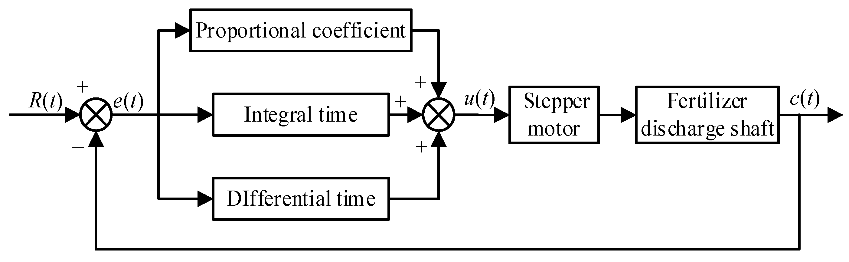
2.4. PID Control Algorithm of Stepper Motors

After determining the mathematical model and transfer function model of the stepper motor, the STM32F4 MCU was adopted as the core controller. The traditional PID control method is shown in Figure 4. The PID control method is divided into two types: position type and incremental type [28]. This paper selected the incremental-type PID control algorithm to accurately control the rotational speed of the stepper motor and deployed the control algorithm model in the stepper motor controller. At the same time, the stepper motor controller can monitor the actual rotational speed pulse signal of the stepper motor. The PID control algorithm model is shown in Formula (8).
u t = K p e t + 1 T i 0 t e t d t + T d d e t d t
where u(t) is the output of the stepper motor controller, e(t) is the input of the stepper motor controller, Kp is the proportional coefficient of the stepper motor controller, Ti is the integral time of the stepper motor controller, and Td is the differential time of the stepper motor controller.
The Laplace transform method of the PID control algorithm model is shown in Formula (9).
G s = K p 1 + 1 T i s + T d s
In the stepper motor controller, the stability of the precise fertilizer discharge module was adjusted by calculating the increment of the system. At present, domestic and foreign scholars carry out much research on parameter tuning of control systems. For parameter tuning, the Ziegler–Nichols method, the critical proportionate method, the control system tuner (CST), particle swarm optimization (PSO), SSA, GA, and other algorithms have been proposed [22,29]. All of these methods had good optimization characteristics. In this paper, a CST toolbox based on the Simulink platform and a PSO algorithm based on global search were selected for parameter tuning, and the effects of the two parameters in the system simulation process were compared as well.

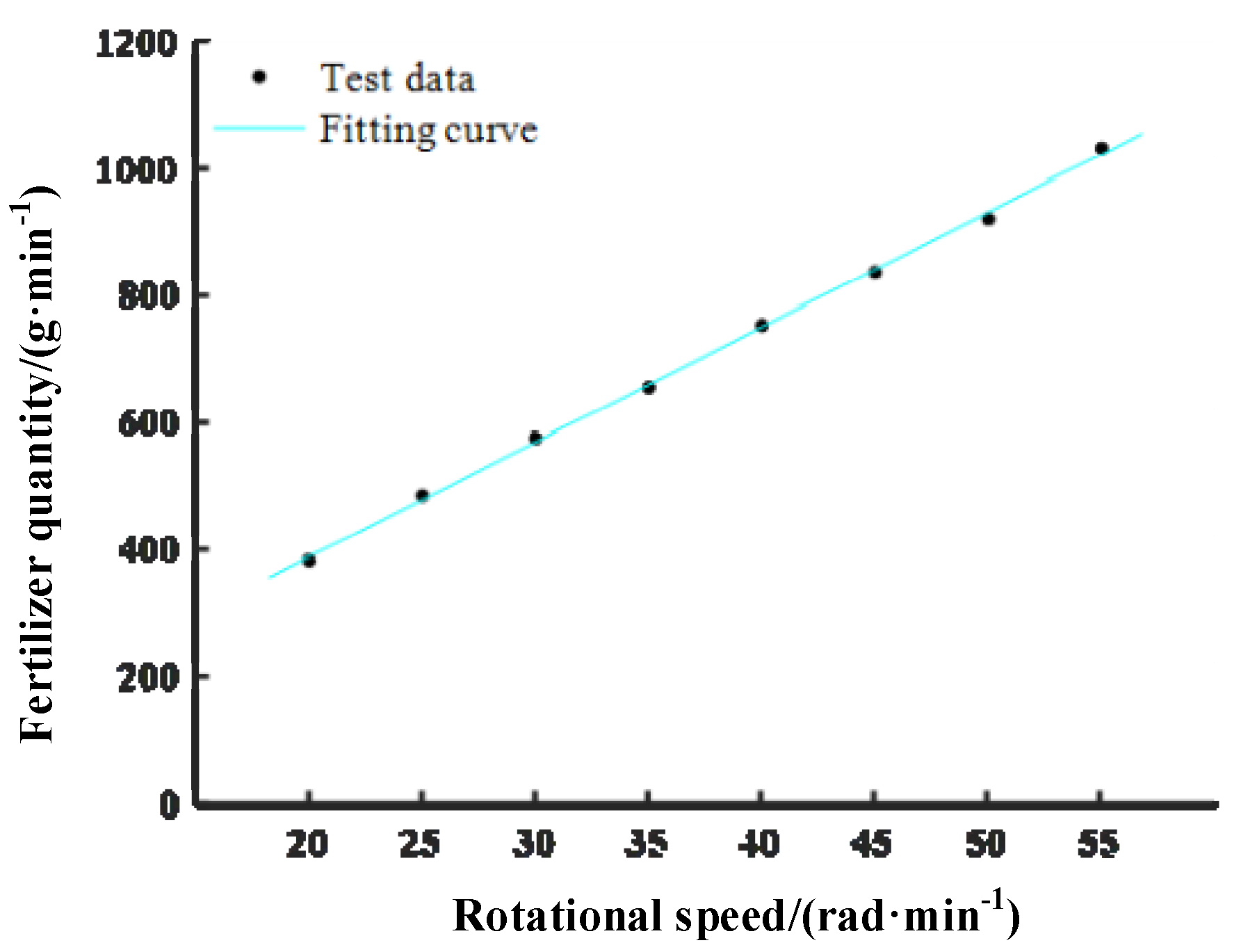
2.5. Mathematical Model of Fertilizer Discharge and Stepper Motor Rotational Speed

It is necessary to establish mathematical models of fertilizer discharge and stepper motor speed for an air-assisted side-deep fertilization machine. In order to establish a mathematical model between fertilizer discharge and stepper motor rotational speed, we selected eight stepper motor rotational speed levels, including 20, 25, 30, 35, 40, 45, 50, and 55 r/min. The stepper motor was operated for 1 min each time, and the discharged fertilizer was weighed and recorded. The experiment was repeated three times to reduce experimental errors.
In the experiment, the experimental material was carbamide with a total nitrogen content greater than 46% (China Salt Anhui Hongsifang Fertilizer Industry Co., Ltd.: Hefei, China), and the weighing test instrument was a YP10002 electronic scale (Shanghai Youke Instrument and Meter Co., Ltd.: Shanghai, China).

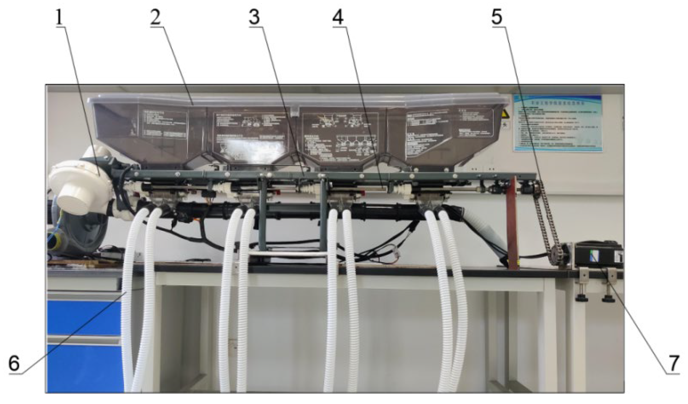
2.6. Construction of Validation Test Platform

We had constructed an air-assisted side-deep fertilization test platform, as shown in Figure 5. We used this platform to test the stability of the program. The platform was based on 2 FG side-deep fertilizing devices (Jiangsu World Group: Zhenjiang, China). Through the stepper motor controller, a predetermined rotational speed was applied to the Venturi fertilizer apparatus to discharge the fertilizer quantitatively. The test platform was powered using a transformer (AC220V-DC24V). The stepper motor controller converted the set value into the rotational speed information of the stepper motor and drove the fertilizer discharge shaft to rotate at the specified rotary speed.

3. Results and Discussion

3.1. Parameter Setting Results of CST

CST can be introduced using MathWorks in the industrial field; it could adjust the structure of the system to meet the target parameters. The stepper motor control model of the precise fertilizer discharge module was established in Simulink (Software version: R2020a), and the joint debugging was carried out through MATLAB (2022a)/Simulink. The simulation program was designed according to the incremental PID control algorithm. The precise fertilizer discharge module was built in Simulink. Based on the transfer function model obtained above, the precise fertilizer discharge module used the CST toolbox to adjust the parameters. The parameter values of the precise fertilizer discharge module were solved by adjusting the response curve of the unit step. Parameters were downloaded to the PID controller, and the response time was also compared.
The simulation results of Kp, Ki, Kd, and N were 14.01, 55.72, 0.7781, and 667.1, respectively. Under these parameters, different input rotational speeds of 25, 50, 75, and 100 r/min were set, and the response characteristic curve was drawn as shown in Figure 6. When the rotational speed was 100 r/min, the maximum overshoot was 14.4, and the response time was 1.5 s. As shown in Figure 6, the overshoot increased with the increase in rotational speed, and the response time was roughly the same.

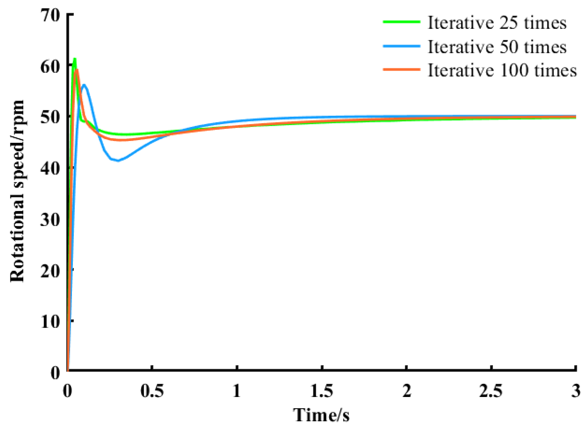
3.2. Parameter Setting Results of PSO

The PSO algorithm was used to find the optimal solution for the parameters. Firstly, three parameters, Kp, Ki, and Kd were determined to be solved. The PSO algorithm contained three important parameters: inertia weight ω and velocity adjustment parameters η1 and η2. In MATLAB, the three parameters of ω, η1, and η2 were determined as 0.8, 2, and 2 [30]. In addition, the particle swarm size was 10, the minimum fitness value was 0.001, and the number of iterations was 25, 50, and 100, respectively, to obtain the optimal solution under different iterations. These were entered into the Simulink model for comparison.
At 25 iterations (Kp = 10, Ki = 10, Kd = 0.99), 50 iterations (Kp = 6.99, Ki = 10, Kd = 0.7), and 100 iterations (Kp = 3.05, Ki = 10, Kd = 0.32), numerical iterations are shown in Figure 7. From Figure 7, with the increase in iteration number, we see that the response time was stable at 1.5 s, the overshot was reduced, and the robustness and responsiveness of the control system were gradually optimized.
The input parameter values were obtained from different iterations of the system model. In the Simulink model, the input signal was set at 50 r/min to obtain the response characteristic curves under the three optimization parameters (Figure 8). As shown in Figure 8, the response time of the system was longer, and the overshot was greater than 10 when the iteration was 25 times. With the numerical increase in iterations, the overshoot tended to be stable, and the response time was short. After 100 iterations, the response time of the system met the needs of the system, and the final parameters of Kp, Ki, and Kd were determined to be 3.05, 10, and 0.32, respectively.

3.3. Results of Mathematical Model between Fertilizer Discharge and Stepper Motor Rotational Speed

The mathematical relationship between fertilizer discharge and stepper motor rotational speed was measured through the test, and the relevant experimental results are shown in Figure 9. Then, through regression analysis of the MATLAB Cftool toolbox, the mathematical model was obtained from Formula (10).
M = 1.81 N + 26.83
where M is the amount of fertilizer discharged per unit time, g/min, and N is the rotational speed of the stepping motor, r/min.
In the mathematical model of Formula (10), R2 and SSE were 0.99 and 365, respectively, which showed a good fitting degree. So, the mathematical model can better reflect the relationship between fertilizer discharge and stepper motor rotational speed.

3.4. Platform Test Results of Precise Fertilizer Discharge Control System

The precise fertilizer discharge control system selected eight target fertilizer discharge mass levels, including 350, 450, 550, 650, 750, 850, and 900 g/min, and the actual maximum mass within 30 s from the equipment was collected and recorded. Every test was repeated five times to reduce experimental errors. The test results are shown in Table 1.
From Table 1, we can see that the maximum stability coefficient of variation at 350 g/min of target fertilizer discharge mass level is 0.91%, and the maximum error of fertilizer discharge at 550 g/min of target fertilizer discharge mass level is 4.14%. When the target fertilizer discharge mass is 750 g/min, the stability coefficient of variation is the minimum value (0.39%). And when the target fertilizer discharge mass is 950 g/min, the error of fertilizer discharge is the minimum value (0.89%). By analyzing the test results of the precise fertilizer discharge control system, the new precise fertilizer discharge control system had good fertilizer discharge stability and could also meet the technical specification for quality evaluation of fertilization machinery (NY/T 1003-2006).
We also compared the performance of the new precise fertilizer discharge control system with Zuo, X. [13]. Zuo, X. et al. [13] developed an air-blast rice side-deep precision fertilization device, and this device adopted the modularization design and was combined with a riding-type rice transplanter for use. When presetting the fertilization amount to 300 kg/hm2, the fertilizer difference test with six fertilizer discharging ports was carried out, and the coefficients of variation of the fertilizer application amounts were 2.3%, 2.1%, 2.2%, and 1.8%, respectively. The new precise fertilizer discharge control system has higher working accuracy.

4. Conclusions

The purpose of this study was to design a precise fertilizer discharge control system that will enable the precise fertilizer adjustment of an air-assisted side-deep fertilization machine. Firstly, we established a mathematical model and transfer function model of a stepper motor and a mathematical model between fertilizer discharge and stepper motor rotational speed. Then, the parameters of the system were simulated using different algorithms. Finally, the PID control system parameters of Kp, Ki, and Kd were determined as 3.05, 10, and 0.32, respectively.
In order to test the performance of a precise fertilizer discharge control system, we established a validation test platform. In the actual experiment, the maximum stability coefficient of variation at 350 g/min of target fertilizer discharge mass level was 0.91%, and the maximum error of fertilizer discharge at 550 g/min of target fertilizer discharge mass level was 4.14%. By analyzing the test results of the precise fertilizer discharge control system, the new precise fertilizer discharge control system had good fertilizer discharge stability and could also meet the technical specification for quality evaluation of fertilization machinery (NY/T 1003-2006). This research can improve the fertilizer discharge accuracy of the air-assisted side-deep fertilization control system.

Author Contributions

Conceptualization, Q.Z. and L.C.; methodology, Q.Z. and H.Z.; validation, Z.Z. and Y.G.; formal analysis, H.Z. and Z.Z.; investigation, L.C. and Y.G.; resources, L.C.; data curation, Q.Z. and H.Z.; writing—original draft preparation, Q.Z. and H.Z.; writing—review and editing, Q.Z. and L.C. All authors have read and agreed to the published version of the manuscript.

Funding

This work was supported by the National Natural Science Foundation of China (Grant No. 32301712), the Natural Science Foundation of Jiangsu Province (Grant No. BK20230548), the Jiangsu Postdoctoral Sustentation Fund (Grant No. 2020Z378), and the Open Fund of Key Laboratory of Transplanting Equipment and Technology of Zhejiang Province (Grant No. 2023E 10013-01).

Institutional Review Board Statement

Not applicable.

Data Availability Statement

The data presented in this study are available in the article.

Conflicts of Interest

The authors declare no conflict of interest.

References

  1. Min, J.; Sun, H.; Wang, Y.; Pan, Y.; Kronzucker, H.J.; Zhao, D.; Shi, W. Mechanical side-deep fertilization mitigates ammonia volatilization and nitrogen runoff and increases profitability in rice production independent of fertilizer type and split ratio. J. Clean. Prod. 2021, 316, 128370. [Google Scholar] [CrossRef]
  2. Wang, J.; Wang, Z.; Weng, W.; Liu, Y.; Fu, Z.; Wang, J. Development status and trends in side-deep fertilization of rice. Renew. Agric. Food Syst. 2022, 37, 550. [Google Scholar] [CrossRef]
  3. Zha, X.; Zhang, G.; Zhang, S.; Hou, Q.; Wang, Y.; Zhou, Y. Design and experiment of centralized pneumatic deep precision fertilization device for rice transplanter. Int. J. Agric. Biol. Eng. 2020, 13, 109–117. [Google Scholar] [CrossRef]
  4. Shen, J.; Zhang, F.; Siddique, K. Sustainable resource use in enhancing agricultural development in China. Engineering 2018, 4, 21–24. [Google Scholar] [CrossRef]
  5. Chen, X.; Cui, Z.; Fan, M.; Vitousek, P.; Zhao, M.; Ma, W.; Wang, Z.; Zhang, W.; Yan, X.; Yang, J.; et al. Producing more grain with lower environmental costs. Nature 2014, 514, 486–489. [Google Scholar] [CrossRef]
  6. Wang, J.; Gao, G.; Weng, W.; Wang, J.; Yan, D.; Chen, B. Design and experiment of key components of side deep fertilization device for paddy field. Trans. Chin. Soc. Agric. Mach. 2018, 49, 92–104. [Google Scholar]
  7. Wang, J.; Gao, G.; Wang, J.; Yan, D. Design and test of adjustable blades side deep fertilizing device for paddy field. Trans. Chin. Soc. Agric. Mach. 2018, 49, 68–76. [Google Scholar]
  8. Yang, X.; Chen, B.; Xing, H.; Zhen, W.; Qi, L. Design and experiments of the side-deep fertilization device with sliding-knife furrow opener and pneumatic ejector for a liquid fertilizer atomizer. Trans. Chin. Soc. Agric. Eng. 2023, 39, 13–25. [Google Scholar]
  9. Chen, X.; Luo, X.; Wang, Z.; Zhang, M.; Hu, L.; Zeng, S.; Mo, Z. Experiment of synchronous side deep fertilizing technique with rice hill-drop drilling. Trans. Chin. Soc. Agric. Eng. 2014, 30, 1–7. [Google Scholar]
  10. Wang, J.; Fu, Z.; Weng, W.; Wang, Z.; Wang, J.; Yang, D. Design and experiment of conical-disc push plate double-row fertilizer apparatus for side-deep fertilization in paddy field. Trans. Chin. Soc. Agric. Mach. 2023, 54, 53–62. [Google Scholar]
  11. Wang, J.; Liu, Y.; Weng, W.; Wang, J.; Fu, Z.; Wang, Z. Design and experiment of chute rotary side deep fertilizing device in paddy field. Trans. Chin. Soc. Agric. Mach. 2022, 53, 76–85. [Google Scholar]
  12. Wang, J.; Shang, W.; Weng, W.; Wang, J.; Wang, Q.; Chen, X. Design and experiment of disc ejection type paddy field side deep fertilization device. Trans. Chin. Soc. Agric. Mach. 2021, 52, 62–72. [Google Scholar]
  13. Zuo, X.; Wu, G.; Fu, W.; Li, L.; Wei, X.; Zhao, C. Design and experiment on air-blast rice side deep precision fertilization device. Trans. Chin. Soc. Agric. Eng. 2016, 32, 14–21. [Google Scholar]
  14. Wang, J.; Li, S.; Zhang, Z.; Li, Q. Design and experiment of electrical drive side deep hill-drop fertilization system for precision rice hill-direct-seeding machine. Trans. Chin. Soc. Agric. Eng. 2018, 34, 43–54. [Google Scholar]
  15. Yang, R.; Chen, D.; Zha, X.; Pan, Z.; Shang, S. Optimization design and experiment of ear-picking and threshing devices of corn plot kernel harvester. Agriculture 2021, 11, 904. [Google Scholar] [CrossRef]
  16. Liu, Y.; Zhou, Y.; Lv, W.; Huang, H.; Zhang, G.; Tu, M.; Huang, L. Design and experiment of hydraulic scouring system of wide-width lotus root digging machine. Agriculture 2021, 11, 1110. [Google Scholar] [CrossRef]
  17. Pareek, C.; Tewari, V.; Machavaram, R.; Nare, B. Optimizing the seed-cell filling performance of an inclined plate seed metering device using integrated ANN-PSO approach. Artif. Intell. Agric. 2021, 5, 1–12. [Google Scholar] [CrossRef]
  18. Cousins, J.; Noble, S. Fast gas-solid flow simulation for air seeder control applications. In Proceedings of the 2019 ASABE Annual International Meeting, Boston, MA, USA, 7–10 July 2019; p. 1901667. [Google Scholar]
  19. Wei, G.; Qi, B.; Jiao, W.; Shi, S.; Jian, S. Design and experiment of mechanical forced fertilizing device for paddy field. Trans. Chin. Soc. Agric. Mach. 2020, 51, 154–164. [Google Scholar]
  20. Zeng, S.; Zheng, Z.; Yang, Z.; Luo, X.; Tan, Y.; Mo, Z. Design and test of airflow layered fertilizer system for rice direct seeder. Trans. Chin. Soc. Agric. Eng. 2020, 36, 1–9. [Google Scholar]
  21. Zhu, Q.; Zhang, H.; Zhu, Z.; Gao, Y.; Chen, L. Structural design and simulation of pneumatic conveying line for a paddy side-deep fertilisation system. Agriculture 2022, 12, 867. [Google Scholar] [CrossRef]
  22. Wang, B.; Luo, X.; Wang, Z.; Zheng, L.; Zhang, M.; Dai, Y.; Xing, H. Design and field evaluation of hill-drop pneumatic central cylinder direct-seeding machine for hybrid rice. Int. J. Agric. Biol. Eng. 2018, 11, 33–40. [Google Scholar] [CrossRef]
  23. Lei, X.; Liao, Y.; Zhang, Q.; Wang, L.; Liao, Q. Numerical simulation of seed motion characteristics of distribution head for rapeseed and wheat. Comput. Electron. Agric. 2018, 150, 98–109. [Google Scholar] [CrossRef]
  24. Zha, X.; Zhang, G.; Han, Y.; Han, Y.; Salem, A.E.; Fu, J.; Zhou, Y. Structural optimization and performance evaluation of blocking wheel-type screw fertilizer distributor. Agriculture 2021, 11, 248. [Google Scholar] [CrossRef]
  25. Lei, X.; Liao, Y.; Liao, Q. Simulation of seed motion in seed feeding device with DEM-CFD coupling approach for rapeseed and wheat. Comput. Electron. Agric. 2016, 131, 29–39. [Google Scholar] [CrossRef]
  26. Tola, E.; Kataoka, T.; Burce, M.; Okamoto, H.; Hata, S. Granular fertiliser application rate control system with integrated output volume measurement. Biosyst. Eng. 2008, 101, 411–416. [Google Scholar] [CrossRef]
  27. Toomey, C. Pneumatic conveying system optimization. IEEE Trans. Ind. Appl. 2014, 50, 4319–4322. [Google Scholar] [CrossRef]
  28. Zhu, Q.; Wu, G.; Zhu, Z.; Zhang, H.; Gao, Y.; Chen, L. Design and test on winter wheat precision separated layer fertilization and wide-boundary sowing combined machine. Trans. Chin. Soc. Agric. Mach. 2022, 53, 25–35. [Google Scholar]
  29. Keep, T.; Noble, S. Optical flow profiling method for visualization and evaluation of flow disturbances in agricultural pneumatic conveyance systems. Comput. Electron. Agric. 2015, 118, 159–166. [Google Scholar] [CrossRef]
  30. Wang, Z.; Zhang, L.; Peng, Z. Design of fuzzy pid excitation control based on PSO optimization algorithm. J. Hunan Univ. Nat. Sci. 2017, 44, 106–111+136. [Google Scholar]
Figure 1. Structure diagram of an air-assisted electronic fertilizer discharge system: 1. Conveying fan; 2. Wind speed sensor; 3. Fertilizer box; 4. Support mechanism; 5. Venturi fertilizer apparatus; 6. Fertilizer discharge shaft; 7. Transmission chain; 8. Fertilizer discharge stepper motor; 9. Driver; 10. Stepper motor controller; 11. Terminal controller; 12. Furrow opener; 13. Fertilizer pipeline.
Agriculture 13 02210 g001
Figure 2. Working principle of a precise fertilizer discharge module.
Agriculture 13 02210 g002
Figure 3. Circuit diagram of stepper motor control: (a) the stepper motor control circuit; (b) the rotational speed feedback circuit.
Agriculture 13 02210 g003
Figure 4. PID control system diagram.
Agriculture 13 02210 g004
Figure 5. Air-assisted electric control fertilization test platform: 1. Conveying fan; 2. Fertilizer box; 3. Support mechanism; 4. Venturi fertilizer apparatus; 5. Transmission chain; 6. Fertilizer pipeline; 7. Fertilizer discharge stepper motor.
Agriculture 13 02210 g005
Figure 6. Response characteristic curves of the system at different rotary speeds.
Agriculture 13 02210 g006
Figure 7. Numerical iterative optimization: (a) 25 iterations; (b) 50 iterations; (c) 100 iterations.
Agriculture 13 02210 g007
Figure 8. Comparison of optimization results.
Agriculture 13 02210 g008
Figure 9. Relation curve of fertilizer discharge and stepper motor rotational speed.
Agriculture 13 02210 g009
Table 1. Results of precise fertilizer discharge control system.
NumberTarget Fertilizer Discharge Mass/(g·min−1)Actual Maximum Mass within 30 s/(g)Actual
Minimum Mass within 30 s/(g)
Actual Average Mass within 30 s/(g)Stability
Coefficient of Variation/(%)
Error of
Fertilizer
Discharge/(%)
1350179.97174.45178.080.911.76
2450223.96220.54222.190.491.25
3550288.56285.19286.380.434.14
4650329.52325.78328.030.400.93
5750369.31365.75366.930.392.15
6850434.76426.49431.450.881.52
7950475.02466.03470.750.680.89
Disclaimer/Publisher’s Note: The statements, opinions and data contained in all publications are solely those of the individual author(s) and contributor(s) and not of MDPI and/or the editor(s). MDPI and/or the editor(s) disclaim responsibility for any injury to people or property resulting from any ideas, methods, instructions or products referred to in the content.

