Article

Design and Experiment of Flexible Threshing Device with Variable Stiffness for Corn

College of Agricultural Engineering and Food Science, Shandong University of Technology, Zibo 255200, China
*
Author to whom correspondence should be addressed.
Agriculture 2024, 14(6), 836; https://doi.org/10.3390/agriculture14060836
Submission received: 18 April 2024 / Revised: 23 May 2024 / Accepted: 24 May 2024 / Published: 27 May 2024
(This article belongs to the Section Agricultural Technology)

Abstract

:
In order to solve the problem of the high damage rate of corn with a high moisture content in the Huanghuaihai region, according to the mechanical characteristics of corn in the Huanghuaihai region, we designed a flexible threshing device with a threshing rasp bar and variable stiffness spring as the buffer carrier, and the elements of the device were nail teeth and a flexible threshing rasp bar, which could be replaced freely. The experiment was based on the threshing rotor speed, threshing gap, and spring stiffness as the influencing factors, with the grain breakage rate and the unthreshed rate as an indicator of three-factor three-level experiments, and in October in Zibo through bench experiments, to determine the best parameter combinations. When the spring compression stiffness was 20.83 N/mm, the rotor speed was 375 r/min, and the gap of the concave plate was 45 mm, the grain breakage rate of the corn ear was 4.7%, and the unthreshed rate was 0.48%, which is in line with the relevant national standards.

1. Introduction

Corn is the largest grain crop in China, which is of great significance to ensure national food security. However, affected by many factors, it is still in the stage where corn ear harvesting is predominant, which not only restricts the improvement in the mechanization level of corn harvest, but also reduces the economic benefits of corn production. The bottleneck technology in corn harvesting is how to control and reduce the grain damage and loss in the harvest process.
At present, low-loss and high-efficiency threshing is one of the core technologies of mechanized corn harvesting, which is of great significance to ensure the quality of corn harvesting and improve the efficiency of corn harvesting [1]. Traditional corn threshing mainly uses the rigid impact of threshing elements on the corn ear to separate the grain from the corn. Although it has the advantage of simple structure, the problem of grain damage is prominent, which increases the risk of mold infection and poses a great threat to the safe storage of corn [2].
To solve the above problems, a lot of research has been carried out abroad, mainly from the perspective of the structural optimization of threshing devices. For example, Kiniulis et al. [3] investigated the influence of threshing rotor filler plates on the threshing and grain separation losses as well as the grain separation intensity through concave and grain damage. It was found that an increased feed rate resulted in an increase in the influence of the shape of the spaces between the rotor rasp bars. Grain damage was minimized when the threshing rotor was covered with the FP-III threshing sleeve (the working plane of the threshing rotor was at an angle of 36° to the rotor radius). Saeng-ong et al. [4] investigated the effects of the guide vane inclination of an axial shelling unit on the corn shelling performance and found that when the guide vane inclination increased, the loss from the shelling unit had a tendency to decrease, the power requirements and specific energy consumption tended to increase linearly, and the grain breakage difference was not significant. Whereas for the rotor speed and feed rate, an increased rotor speed could decrease the loss from shelling, while the grain breakage, power requirements, and specific energy consumption tended to increase. Petkevičius et al. [5] found that the grain biometrical indices, technological parameters of the threshing apparatus, and the feed rate of the corn ears appeared to be the most significant causes of threshing losses, grain damage, and the threshed amount of grains thrown to the straw walkers. The concave gap at the beginning should be about 10 mm smaller than the average diameter of the corn ear, and finally equal to the diameter of the corn ear for the best threshing results. Pužauskas et al. [6] found by comparison that the use of a concave crossbar was more efficient than the use of two other crossbar shapes during the threshing of corn ears. Threshing losses and grain damage were minimized when using a concave crossbar with a variable radius at an angle of inclination of the working surface equal to 45°.
Domestic experts and scholars have also carried out research on this subject. Cheng et al. [7,8,9,10] conducted experiments to determine the parameters of corn, analyzed the physical parameters of corn grain at different moisture contents, and concluded that with the increase in moisture content, the destructive force, destructive energy, modulus of elasticity, etc. of the corn grain decreased, and the destructive strain increased. Xie et al. [11] used flexible nail teeth threshing to increase the contact time with the corn ears and reduce the impact force under a certain rotor speed and found that a flexible nail teeth threshing rotor with diameters smaller than the rigid nail teeth could be well-adapted to the rice threshing requirements. Jin et al. [12] found that compared with the traditional rigid nail teeth, flexible nail teeth formed a series of continuous normal striking force and many times repeated tiny tangential kneading forces in striking, which helped to improve the threshing rate and reduce the damage rate of the grains. Li et al. [13] carried out a systematic study on a flexible threshing device for corn, and with the help of the Hertz contact theory, they analyzed the loading characteristics of threshing elements on the corn grains and proved that the extended time between the corn and the threshing element could reduce the intensity of corn threshing as well as the damage and loss of grains. Zhang et al. [14] studied the effect of the structure of the threshing element on the damage and loss of the corn and developed the threshing technology of roundhead nail teeth and a rasp bar with the segmented combination of a concave plate, which achieved a significant reduction in the damage of the corn. Diao et al. [15] developed a flexible threshing device with double torsion spring action, where the threshing process of the rasp bar and corn ear produced rigid impact through the torsion compression spring torsion to absorb the instantaneous high impact force to ensure that the intensity of the external force of threshing was in the safety threshold, in order to reduce the mechanical damage to the corn.
On the basis of the above research, the authors conducted research on the seed damage resistance strength, combined the grain damage resistance strength with flexible threshing, and carried out an investigation of flexible threshing technology with variable stiffness, which provides theoretical and technical support for breaking through the grain damage and loss in the process of direct threshing.

2. Materials and Methods

2.1. Grain Damage Regulation

In order to minimize corn grain damage and safeguard the threshing efficiency, the damage resistance characteristics of the corn grain were investigated using a grain compression test device and point contact loading to determine the damage resistance of the top, side, and front surfaces of the corn grain. As shown in Figure 1, the damage resistance of the surface of the corn grain varied greatly, and the damage resistance of the top surface of the corn grains was relatively small. The front and sides of the grain had relatively high damage resistance, so the threshing load was loaded as much as possible on the front and sides, avoiding the top to minimize damage to the grains. Furthermore, for the whole corn ears, due to the agglomeration distribution of the corn grains, it is difficult to apply the threshing load on the front side of the grain. Although the damage resistance strength of the side was not the largest, it also reached [91.72, ±5.46] MPa. In the corn threshing process, limited by the threshing gap, the corn is mostly in the direction close to parallel to the threshing rotor axis, so the threshing action exerted by the threshing elements on the grains is preferably at the lateral side. Furthermore, considering the characteristics of the lateral damage resistance distribution, in the upper half of the corn grain, the damage resistance is higher than the lower half (Figure 1c), so the loading position can further be accurate to the position of [5.75, 8.1] mm of the seed grain height.
Furthermore, in order to determine the strength of the loading force, the loading characteristics of the sides were investigated, and the average results of the measurements are shown in Figure 2. For the sides of the corn grain, with the increase in the surface load, the surface deformation also began to increase, and in the early stage of the performance of the deformation and the loading force in a linear relationship. In the late stage, the performance of the compression displacement changed dramatically, but the change in the loading force was slow, and then the corn grain suddenly ruptured. Based on this characteristic and the previous research on flexible threshing technology, although ordinary cylindrical springs (stiffness is constant) can be deformed to achieve control of the threshing load, it requires a large amount of deformation in order to achieve a significant reduction in the threshing load. Conical springs (stiffness increases with the increase in load) have the characteristics of variable stiffness, so for conical springs, with the increase in pressure, the greater the change in stiffness [16], so the amount of deformation required is much smaller than that of cylindrical springs.
The grain characteristic curve with an average moisture content of 30% was obtained by conducting a corn grain loading experiment in the laboratory [17]. According to the grain characteristic curve, for corn grains, the load change gradually increases regardless of the loading mode in any direction, while the load change slows down and the load change per unit displacement decreases at the end; after that, the critical point is reached, and the grain is broken. The spring was used to control the change in grain load, and the cylindrical spring was a fixed stiffness spring; to meet the load demand, its deformation exceeded the displacement deformation of the end of the seed [18]. According to the corn grain breakage curve, with the use of conical springs for grain load change control, the conical spring in the compression of the late stage shows the occurrence of a small deformation of its spring load change for the curve rising. The load change amplitude is large and can meet the load strength requirements.

2.2. Machine Structure and Working Principle

2.2.1. Overall Structure

According to the current research status of corn flexible threshing, combined with the change rule of corn grain damage strength, the developed flexible threshing test machine is shown in Figure 3, which mainly consists of a flexible rotor, threshing concave plate, screw pusher, guide plate, upper cover, shell, frame, feed mouth and aggregate box, transmission device, etc.
In order to control the threshing process of the threshing element on the corn ear cycle of the number of threshings, the spiral distribution threshing element was combined with the helical guide plate to achieve the control of the threshing time of the ear. In order to reduce the threshing damage and loss, the threshing element adopted a variable stiffness flexible threshing structure, which realized the control of the threshing intensity in the threshing process. In order to facilitate the detection of the quality of the grains, a collection box was set up under the concave plate, which realized the collection of the threshed grains. The power control device was driven by a three-phase asynchronous motor controlled by the inverter, which realized control of the rotor speed during the test. The main parameters are shown in Table 1.

2.2.2. Working Principle

When the test bench works, the ears are fed through the feeding area, and are then taken into the threshing rotor by the grasping force of the nail teeth on the threshing rotor to realize the initial threshing and separation of the corn ears. In order to reduce the damage of the nail teeth on the grains, the surface of the nail teeth was installed with a rubber sleeve to realize the flexible collision of the ear grasping and threshing process.
When the corn enters the threshing area, they are subjected to the spiral distribution of flexible threshing elements, other grains, and the comprehensive circulation between the concave plate to achieve the separation of the grains from the corn core, in which the removed grains pass through the concave plate screen to enter the bottom aggregate box to collect, while the corn core, bracts, and leaves and other impurities in the spiral distribution of the threshing elements pass through the top cover of the guide plate under the action of the threshing rotor to be sent to the separated area of the threshing rotor and discharged out of the machine, which completes the whole process of threshing.

2.3. The Design of Key Components

2.3.1. Rotor Design

In order to carry out the test process properly, the threshing rotor adopted a three-area structure, namely a feeding area, threshing area, and separated area. Among them, the structure of the feeding area was a nail-tooth structure, and in order to reduce the grain damage during the threshing process, the end of it adopted a rounded-end structure [19]. In order to reduce the rigid impact of the element on the corn ear in the threshing process, the threshing area adopted a variable stiffness flexible threshing element; to strengthen the kneading effect of the threshing process, the surface structure of the flexible element was an inclined groove shape [20]. The whole element adopted a spiral arrangement to enhance the ability of the threshing element to turn and push back the corn ear; the number of spiral heads was four in consideration of the working efficiency and the balanced force of the rotor [21], the threshing rotor is shown in Figure 4.
The threshing and separating model of the axial flow threshing and separating device is as follows [22]:
S S x = 1 λ β λ 1 e β x β ( 1 e λ x ) × 100 %
( B x L )
Formula: S S x —cumulative grain separation rate of threshing rotor, % .
λ —the coefficient of the ratio of the probability of threshing to the amount of unthreshed grain in the area of the concave plate sieve with an adjacent length of Δ x at any point x above the axis of the axial flow roto;
β —the coefficient of the ratio of the probability of separation of grains from the concave plate sieve to the amount of freedom (threshed but not yet separated grains) in the area of the concave plate sieve with an adjacent length of Δ x at any point x on the axis of the axial flow rotor;
x —axial rotor axial position, m ;
B —length of the feeding area of the axial rotor, m ;
L —length of axial rotor, m .
When x = L B , according to the national standard of corn harvester, the threshing loss rate is 1%, then S S x = 99%.
Through the pre-corn moisture content of 30% to 31% of the conditions of the transverse axial flow threshing rotor bench test, λ was 4   m 1 , β was 3.5   m 1 , then L B ≈ 1450 mm; to avoid corn ear arching and clogging of the smallest size to determine the value of B, this design used 450 mm, so the axial flow threshing rotor length of the reference value was 1450 + 450 = 1900 mm.
If the diameter of the threshing rotor is too small, it is easy to block, and the separation area of the concave plate is reduced, but if the diameter of the rotor is too large, the threshing power consumption will increase [23]. According to the manual of agricultural machinery, the diameter of the root circle of the threshing rotor is generally greater than 300 mm, so the test bench selected 400 mm.
The threshing rotor diameter D 2 (the diameter of the top circle) is:
D 2 = D 1 + 2 h
where D 2 is the diameter of the threshing rotor outside circle, mm; D 1 is the diameter of the threshing rotor tooth root circle, mm; h is the height of the threshing element, mm.
The rotor tooth root circle diameter D 1 = 400 mm and the threshing tooth height h = 70 mm, so substitution into Formula (2) can be obtained, where the rotor diameter D 2 = 540 mm.

2.3.2. Spring Design

According to the results of the previous analysis, the equal helix angle truncated conical helix spring [24] was selected.
Stiffness K = 7.5 ~ 15 N/mm, spring precompression point l 1 = 11 ~ 12 mm, termination point l 2 = 14 ~ 16 mm, the spring design is as follows:
Coil number:
n = G d 4 R 2 R 1 16 k R 2 4 R 1 4
where n is the number of coils of the conical spring; k is the spring stiffness, N/mm. R 1 is the diameter of the small end of the conical spring, mm; R 2 is the diameter of the large end of the conical spring, mm.
Helical angle:
α = 32 R 2 2 F Π G d 4 + d 2 Π R 2
where α is the helix angle of the conical spring, ( ° ); F is the load on the spring coil at the start of contact, N; G is cutting edge modulus, G = 78,700   M P a .
Load:
F i = Π G d 4 32 R i 2 α d 2 Π R i
where F i is the actual load on the spring, N; d is the pitch of the conical springs, mm.
Spring deformation:
f i = n R 2 R 1   16 F i G d 4 R i 4 R 1 4 + Π a R 2 2 R i 2 d R 2 R i
where f i is the deformation of the conical spring after the impact of the load, N; R i is at the beginning of contact with the spring coil, the maximum radius in the free loop R i = R 2 , and when completely pressed together, R i = R 1 .
According to the spring parameters determined by the above formula, its load–deformation curve was determined as shown in Figure 5.
The change in the spring stiffness is divided into two stages: the first stage 0~ l 1 is the linear elastic stage; the second stage l 1 ~ l 3 is the superelastic stage [25], and l 1 ~ l 2 is the compression stage. The function of the first stage conforms to the proportional function y 1 = k x . Spring stiffness y 1 = k , while the second stage corresponds to the cubic function y 2 = a x 3 + b x 2 + c x + d . The spring stiffness y 1 = 3 a x 2 + 2 b x + c ; a , b , and c are constants.
Considering the loading characteristics of the grain surface and determining the grain breakage threshold, in order to avoid the threshing load exceeding the grain damage force and ensuring the quality of corn threshing, combined with the late conical spring with the characteristics of the load with the deformation amount of the curves of the relationship, the flexible threshing element was selected for the working state of the conical spring in the position of the grain breakage threshold to achieve the purpose of reducing the damage to corn grains in the context of ensuring the threshing load.

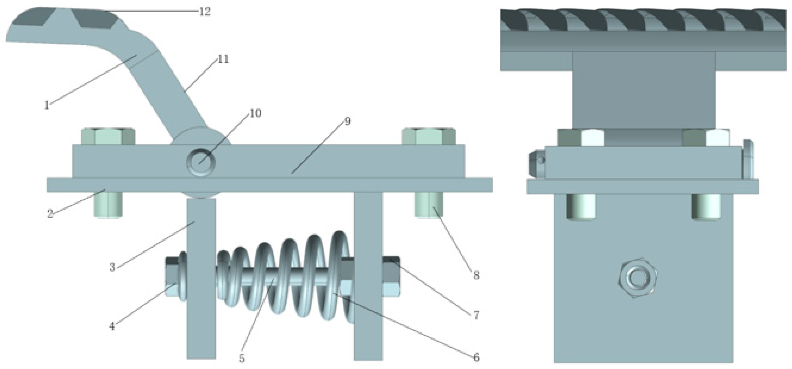
2.3.3. Threshing Element Design

According to the characteristics of the conical spring before and after the deformation stage of the stiffness change in the design of the elastic element, its structure is shown in Figure 6, which is mainly composed of a rasp bar seat, pressure plate, conical spring, and short rasp bar. The rasp bar seat was fixed on the surface of the rotor, the rasp bar was hinged on the rasp bar seat, the conical spring was arranged below the rasp bar seat, and the conical spring was fixed by the conical spring pressure plate and the support plate. The threshing rasp bar was made of D-type ribs steel with a width of 90 mm.
As in the previous section, when the ears enter into the threshing rotor, they first make contact with the flexible threshing element and collide with the element under the action of centrifugal force and gravity. Most of the corn ear is in direct contact with the grain face, resulting in elastic collision, while the rest is in contact with the back surface after rolling collision. At this time, the rasp bar rotates around the rotation center o, and the spring begins to compress. The compression curve is y 2 = a x 3 + b x 2 + c x + d . It can be seen that with the increase in the impact force, the deformation amplitude of the grain rasp bar gradually decreases, the grain rasp bar displacement deformation occurs, the threshing gap becomes larger, and the threshing strength decreases. This process is completed from the traditional instantaneous to a contact–deformation–loading process, which prolongs the contact time between the threshing element and the corn ear during the threshing process.

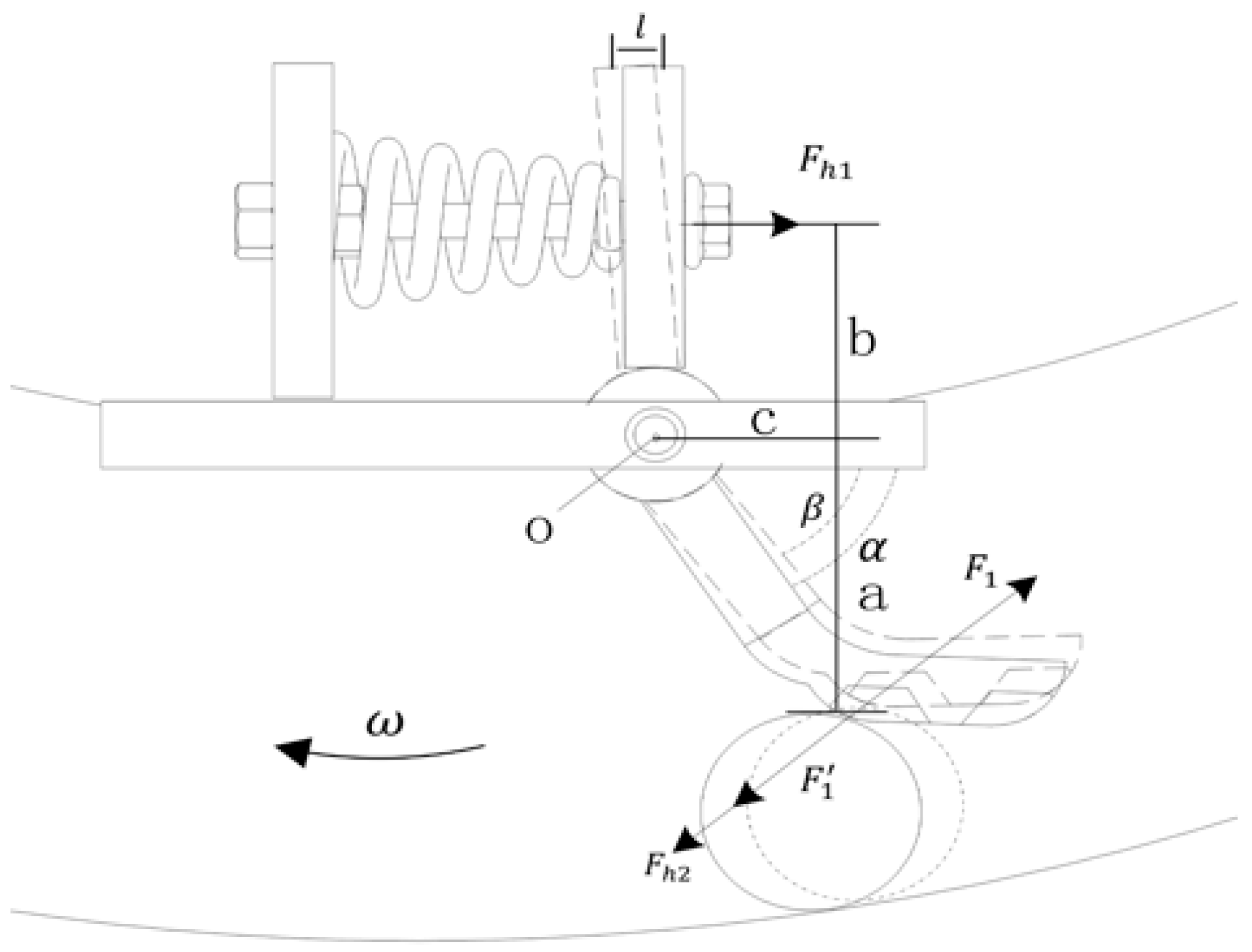
2.3.4. Threshing Element Analysis

The process of corn threshing show in Figure 7, the threshing element rotates with the rotor at the angular speed of ω . In the flexible threshing element, the rasp bar and the rasp bar support seat intersect at the center of rotation o, when the flexible rasp bar is operated; the equivalent maximum impact force of the corn on the rasp bar is F 1 . The actual impact force on the rasp bar is F 1 , part of which is converted into F h 2 of the spring. The initial angle between the back surface of the rasp bar and the horizontal surface is α .
After receiving force F 1 , the grain rasp bar rotates around the rotation center. The initial angle of the grain rasp bar back surface and the horizontal plane becomes β , and the angle between the grain rasp bar surface and the horizontal plane decreases at the same time. The component force of the reaction force F 1 on the cob (the friction along the horizontal direction) increases, and the pressure along the vertical direction decreases. In this process, the rasp bar is subjected to the impact force of the corn ear and the supporting force of the spring, and an unstable balance is formed between the two. The contact point of the impact of the corn ear on the rasp bar is a distance from the center of rotation, and the spring support point is a distance from the center of rotation b . The contact collision between the corn ear and the threshing rasp bar, the threshing rasp bar displacement deformation, the impact force F 1 of the corn ear on the threshing rasp bar means that the corn ear is affected by the impact force, the spring compression, so a part of the direct impact force is absorbed and transformed by the spring transformation. As a result, the threshing rasp bar on the corn ears of the reaction force F 1 is gradually reduced, and the grain breakage rate is reduced.
The compression deformation of the spring:
l = b tan α β
where l is the spring compression deformation about the angle between the back of the striker and the horizontal, mm; b is the distance from the axis of the spring to the rotation center, mm; α is the initial angle of the threshing rasp bar to the horizontal plane, (°); β is the angle of the threshing rasp bar to the horizontal plane after the movement, (°).
The change in the spring end elasticity corresponds to the contact end elasticity:
F h 2 = b s i n β 0 l 1 k i d x + l 1 l 2 ( 2 a i x + b i ) d x a
where F h 2 is the spring force on the corn, N; l 1 is the end node of the linear phase of the conical spring; l 2 is any point in the nonlinear phase of the conical spring.
The contact point between the corn ear and the component was analyzed, and the equivalent force was applied:
F 1 = F h 2 + F 1
where F h 1 is the actual force on the spring, N; F 1 is the actual impact force on the threshing rasp bar, N.
Spring force at this time:
F h 1 = 0 l 1 k i d x + l 1 l 2 ( 2 a i x + b i ) d x
where F h 1 is the pressure actually exerted by the conical spring when the corn collides with the threshing element, N.
Transit moment in motion:
M o = F 1 a s i n β b 0 l 1 k i d x + l 1 l 2 2 a i x + b i d x
where M o is the rotational torque of the threshing element during the entire movement, N.
In the corn threshing process, the use of flexible threshing elements, to a certain extent, increases the threshing process threshing elements and corn ear contact time. The impact force of the element on the corn, part of which is absorbed by the spring, is transformed into the deformation of the spring. Conical spring early stiffness is small, and easy to deform while late stiffness increases, is not easy to deform, and the face of load impact has a good adaptability and can cope with the threshing process of different impact loads on the impact of the element. The cylindrical spring was under the same standard, its stiffness was fixed, and the magnitude of change in the early stage and late stage was the same. Facing a large load impact, the resulting deformation was greater, the deformation reaction time was longer, and the rebound time was longer, so the use of conical springs as a flexible part of the reduction in grain breakage has a better effect.

3. Field Experiments and Analysis of Results

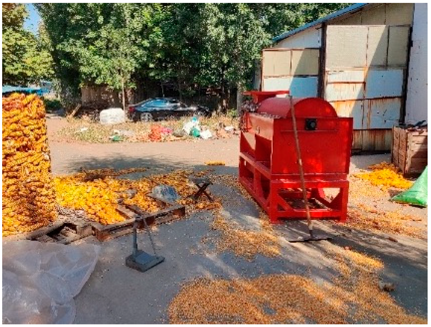
3.1. Test Conditions

The test location was at the Hanling Machinery Factory, Zibo City, Shandong Province, in early October 2023. The threshing test was carried out with the test bench developed by the research team; its structure is shown in Figure 8.
The corn ears used in the experiment were Zhengdan 958, which is commonly planted in Shandong Province, and its parameters are shown in Table 2.

3.2. Test Methods

According to GB/T21961-2008 “Corn Harvesting Machinery Test Method” [26], and GB/T21962-2008 “Corn Harvesting Machinery Technical Conditions” [27], the corn harvesting test bench was tested. The main experimental equipment included a grain moisture tester LDS-1G (Hongxin Electron Co., Dezhou, China), electronic scale ZBC-02 (WeiZhiXiang Co., Zhejiang, China), inverter DC-D60 (DELIXI ELECTRIC Co., Shanghai, China), and tachometer AR925 (SMART SENSOR Co., Dongguan, China).
The grain breakage rate Z s and unthreshed rate S w were selected as the evaluation indices, and the formula was as follows:
Z s = W s W i × 100 %
where Z s is the grain breakage rate, %; W s is the mass of damaged grain, equal to the sum of the mass of grains with visible cracks and broken skins, g; W i is the total grains mass of the sample, g.
S w = W j W z × 100 %
where S W is the unthreshed rate, %; W j is the mass of the unthreshed grain including the mass of all grains in the threshing rotor, in the scratching board, and on the unthreshed corn core, g; W Z is the total mass of grain involved in threshing including the outlet grain, splashed grain, and unthreshed grain, g.

3.3. Orthogonal Test

In order to verify the validation of the effect of different rotor speeds, threshing gaps, spring stiffness on the threshing effect, the Box–Behnken response surface test method was used to carry out orthogonal tests, combined with the relevant literature analysis to determine the threshing rotor speed and threshing gap. According to the grain loading curve to determine the range of spring stiffness to carry out three factors and three levels of Box–Behnken response surface test, the code of each factor is shown in Table 3. Each group of tests was repeated three times, then the average values were taken as the test results, with the grain breakage rate and the unthreshed rate as the evaluation index, the experimental results are shown in Table 4.

3.4. Analysis of Variance

The results of the significance tests obtained through Design-Expert software are shown in the Table 5 and Table 6. The fit of breakage rate was highly significant (p < 0.01), and the misfit term was not significant. The threshing gap, speed, and stiffness all had an influence on the model, and their influence was extremely significant. The influence of X 1 2 , X 2 2 , and X 3 2 was extremely significant, and the influence of X 1 X 3 and X 2 X 3 was significant. The fitting degree of the unthreshed rate was extremely significant (p < 0.01), and the missing fitting term was not significant. The threshing gap, rotor speed, and spring stiffness all had an influence on the model. The influence of the threshing gap and rotor speed was extremely significant, the influence of spring stiffness was significant, the influence of X 1 2 , X 2 2 , and   X 3 2 was extremely significant, and the influence of X 1 X 3 and X 2 X 3 was significant.
According to the data in Table 5 and Table 6, the rotor speed, threshing gap, and spring stiffness had different effects on the grain breakage rate and unthreshed rate, and the three parameters were the main factors affecting the corn grain breakage rate and unthreshed rate. Among them, the main and secondary factors affecting the breakage rate Y1 were, from large to small, threshing gap > rotor speed > spring stiffness.
The main and secondary factors affecting the unthreshed rate Y2 were, from large to small, rotor speed > threshing gap > spring stiffness.
Y1 = +108.02792 − 0.233480X1 − 2.40891X2 − 0.568384X3 + 0.000207X1X2 − 0.000273X1X3 + 0.002331X2X3 + 0.000319X12 + 0.026202X22 + 0.009217X32
Y2 = 0.51525 + −0.0540909X1 + 0.023625X2 + −0.0127273X3 + −0.0163636X1X2 + −0.0125X1X3 + −0.000909091X2X3 + 0.03725X12 + 0.016375X22 + −0.00275X32

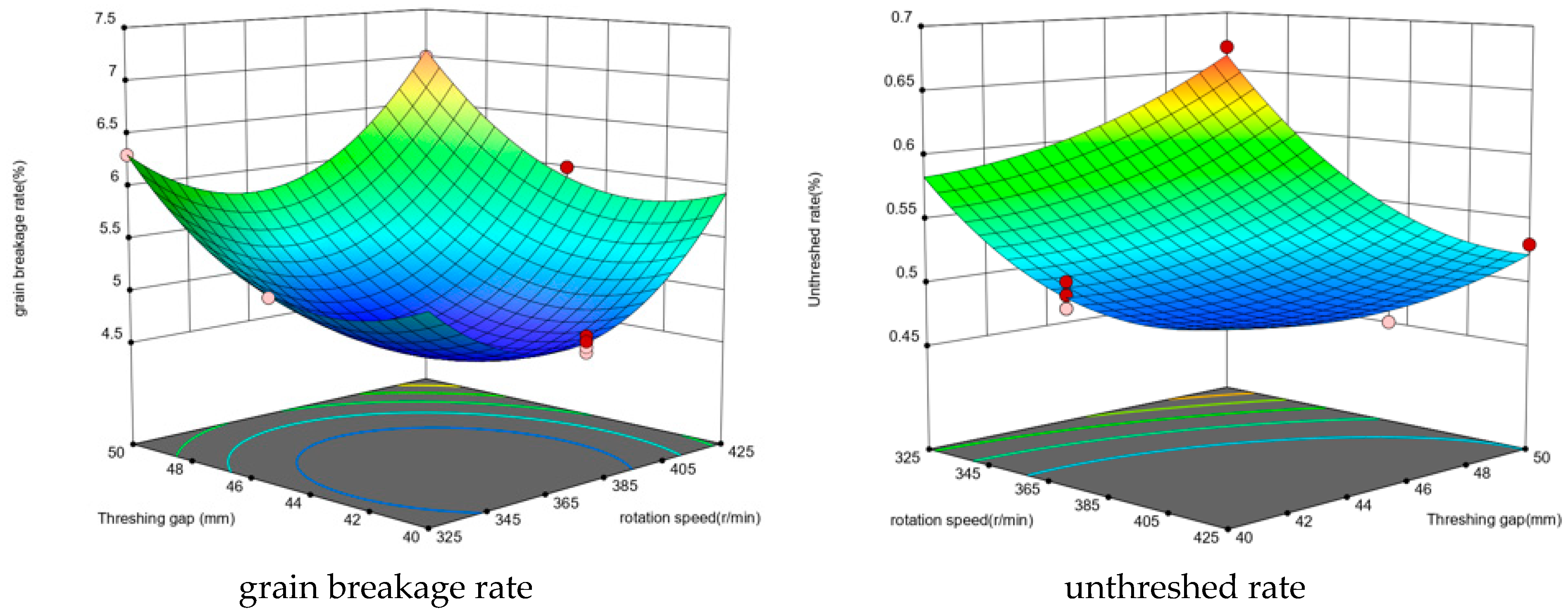
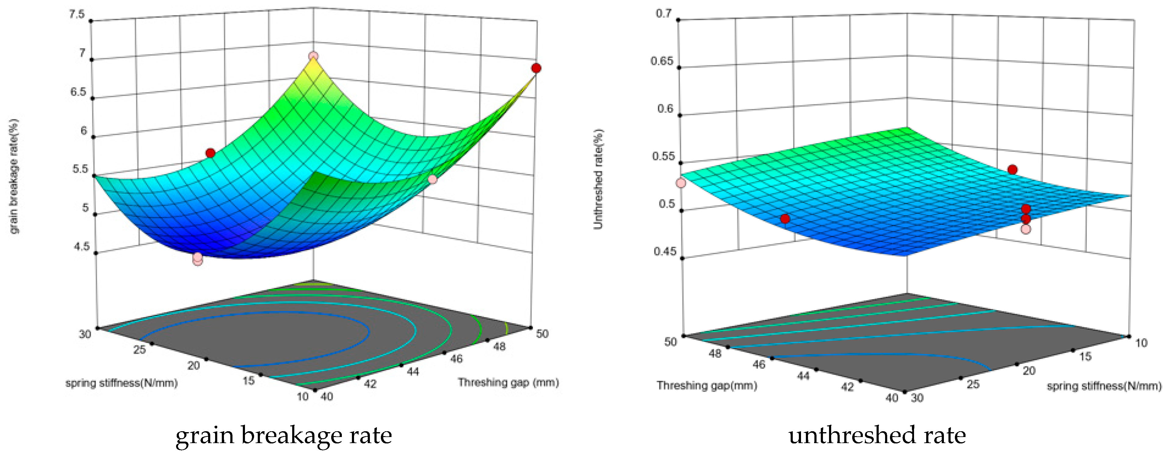
3.5. Response Surface Analysis

As above, a response surface analysis was carried out on the results of the above experiment, considering the interaction of the experimental parameters on the evaluation indices. Fixing one of the three factors at the 0 level, the effects of the other two factors on the grain breakage rate and unthreshed rate were analyzed. The response surfaces of the grain breakage rate under different rotor speeds, threshing gaps, and spring stiffnesses are shown in Figure 9, Figure 10 and Figure 11.
(1) When the spring stiffness is 0 level, the response surface of the rotor speed and threshing gap to the test index is shown in Figure 9.
Figure 9. Response surface of the rotor speed and threshing gap.
Agriculture 14 00836 g009
When the threshing gap is the same, with the increase in rotor speed, the breakage of corn grain is the first to decrease and then increase, the reason being that when the rotor speed of the threshing rotor is low, the impact force acting on the corn grain is low, the grain is not easy to remove, and the number of times of cyclic threshing is increased, which results in the increase in the breakage rate of the corn grain. With the increase in the rotational speed, the corn grain is easy to remove, but due to the larger impact force brought by the increase in rotor speed, the corn grain is easy to break. When the rotational speed is unchanged, with the increase in the threshing gap, the corn grain breakage is the first to decrease and then increase, the reason being that when the threshing gap is smaller than the diameter of the large end of the corn ear, the corn ear is subjected to the squeeze of the concave plate and the kneading force is too large, resulting in the increase in the breakage rate. When the threshing gap is larger than the diameter of the large end of the corn ear, the movement space of the corn ear inside the rotor increases, and the impact movement of the corn ear and the element on the concave plate increases, thus the breakage rates grow slowly.
(2) When the threshing gap is 0 level, the response surface of the rotor speed and spring stiffness to the test index is shown in Figure 10.
Figure 10. Response surface of the rotor speed and spring stiffness.
Agriculture 14 00836 g010
When the spring stiffness is the same, with the increase in rotor speed, the breakage of the corn grain is the first to fall and then rise, and the unthreshed rate is the first to fall and then remain stable, the reason being that when the speed of the threshing rotor is low, the impact force on the corn ear and the kneading force is small, the effect of threshing is low, and the unthreshed corn grain is increased. With the rotor at low speed, the cycle of threshing efficiency is low, and the material impact including rubbing and friction too many times leads to the increase in the breakage rate. Through the continuous improvement in the rotational speed, the impact force and rubbing force acting on the corn ear gradually increase, the threshing element on the corn ear threshing effect is strengthened, and the grain is easy to separate, but when the rotational speed of the rotor is too high, the threshing element on the corn ear threshing strength and frequency increases, and the grain breakage is increased. When the rotational speed is unchanged, with the increase in the spring stiffness, the breakage rate of the corn grain shows a trend of first decrease and then increase, and the unthreshed rate basically remained unchanged. When the spring has a low stiffness, the element deformation was large, the unloading load capacity was weak, the direct impact of the grain was large, and there was a high breakage rate, while with high stiffness, the element deformation was small, the change of the load is small, the unloading capacity is weak, and the impact of the grain is large, and the breakage rate is high.
(3) When the rotor speed is 0 level, the response surface of threshing gap and spring stiffness to the test index is shown in Figure 11.
Figure 11. Response surface of the threshing gap and spring stiffness.
Agriculture 14 00836 g011
When the threshing gap is the same, with the increase in the spring stiffness, the breakage rate of corn grains shows the trend of decreasing and then increasing, and the unthreshed rate basically remains unchanged. The reason for this is that when in the low stiffness of the spring, the element displacement deformation is large, the unloading load capacity is weak, the direct impact of the grains is large, and the breakage rate is high. With the spring in high stiffness, the element deformation is small, the change in the load is small, the unloading capacity is weak, the impact of the grains is large, and the breakage rate is high. When the spring stiffness is the same, with the increase in the threshing gap, the breakage of the corn grain is the first to decline and then rise, the reason being that when the threshing gap is smaller than the diameter of the large end of the corn ear, the corn ear is subjected to the squeeze of the concave plate and the kneading force is too large, resulting in an increase in the breakage rate. When the threshing gap is larger than the diameter of the large end of the corn ear, the movement space of the corn ear inside the rotor increases, and the impact movement of the corn ear and the element on the concave plate increases, so the breakage rates grow slowly.

3.6. Regression Verification

In order to find the optimal working parameters of the flexible threshing rotor, taking the breakage rate as the objective, taking into account the unthreshed rate, and taking the feeding amount, rotor speed, and spring stiffness as the constraints, the quadratic regression model was optimally solved to obtain the optimal combination level of the experimental factors with the objective function and the constraints as follows:
y = ( y 1 , y 2 ) m i n 375   r / m i n X 1 425   r / m i n 40   m m X 2 50   m m X 3 = ( K 1 , K 2 , K 3 )
The optimal working parameters were obtained by using Design-Expert to optimize the solution module. When the rotating speed of the rotor was 375 r/min, the threshing gap was 45 mm, and the spring stiffness was K 2 , the breakage rate was the lowest, which was 4.7%. When the rotating speed of the rotor was 425 r/min, the threshing gap of the concave plate was 40 mm, and the spring stiffness was K 3 , the unthreshed rate was the lowest, which was 0.48%.

4. Discussion

This paper compared the properties and characteristics of cylindrical springs and conical springs. Due to the variable stiffness characteristics of conical springs, the late change in stiffness increase can loading a greater force of the impact. The parameters of the conical springs used in this experiment, based on the moisture content of 30° of the physical characteristics of corn design, showed three different groups of springs. However, the experiment only used one kind of corn, which is a limitation. This experiment only used conical springs to carry out the threshing experiments, and did not use cylindrical springs for experimental comparison, although from the theoretical analysis, conical springs are better than cylindrical springs, but there may be an incomplete analysis of the situation. Therefore, in the future, there is a need to carry out threshing experiments with cylindrical springs to verify the analysis.

5. Conclusions

(1)
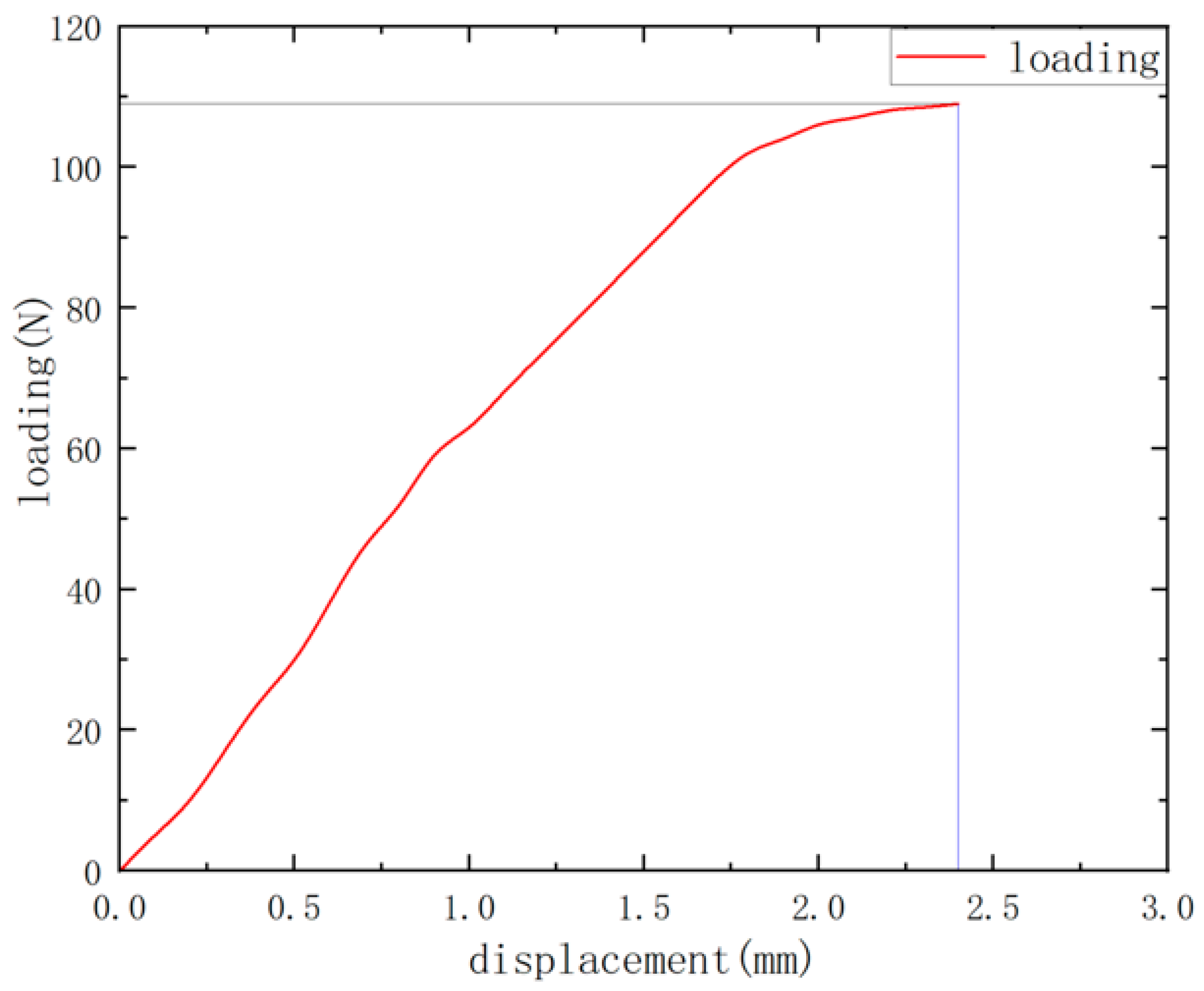
Based on the damage resistance strength of the surface of the corn grain, the damage regulation of corn was summarized, the loading characteristics of corn were studied, the optimal loading direction of corn was determined as the side, and the range of loading positions was determined.
(2)
In order to solve the problem of a high damage rate in the direct harvesting of corn grains in the Huanghuaihai area, a flexible threshing device with a threshing rasp bar and variable stiffness spring as the buffer carrier was developed based on the mechanical characteristics of corn threshing, and the structure of the threshing system and threshing process were studied.
(3)
The conical spring was designed based on the corn load variable regulation, and the optimal parameter combination under the condition of 30~31% moisture content of the corn ear was determined by the orthogonal test. In conclusion, when the rotating speed of the rotor was 375 r/min, the threshing gap was 40 mm, the spring stiffness was K 2 , and the breakage rate was 4.7%. When the rotating speed of the rotor was 425 r/min, the threshing gap was 40 mm, the spring stiffness was K 3 , and the unthreshed rate was 0.48%. Therefore, it meets the national standards (JB/T 10749-2018) [28] of corn threshing.

Author Contributions

Conceptualization, L.N. and D.G.; Methodology, L.N. and D.G.; Software, L.N.; Validation, L.N., D.G. and Z.Z.; Formal analysis, L.N. and D.G.; Investigation, Z.Z., H.Y. and J.M.; Resources, Q.H. and J.M.; Data curation, Y.W. and Y.C.; Writing—original draft preparation, L.N.; Writing—review and editing, D.G.; Visualization, Q.H., H.Y. and Y.W.; Supervision, D.G., X.L. and Z.Z.; Project administration, J.M. and X.L.; Funding acquisition, D.G. All authors have read and agreed to the published version of the manuscript.

Funding

This research was supported by the Natural Science Foundation of Shandong Province (ZR2022ME064). This research was supported by the National Key Research and Development Plan (2021YFD20000502).

Institutional Review Board Statement

Not applicable.

Data Availability Statement

Data are contained within the article.

Conflicts of Interest

The authors declare no conflicts of interest.

References

  1. Cui, T.; Fan, C.; Zhang, D.; Yang, L.; Li, Y.; Zhao, H. Research Progress of Maize Mechanized Harvesting Technology. Trans. Chin. Soc. Agric. Mach. 2019, 50, 1–13. [Google Scholar]
  2. Xiong, W.; Guo, Y.; Meng, S.; Wang, Y.; Sun, Z.; Zhao, Y.; Liu, H.; Yang, G.; Chen, J.; Song, X.; et al. Effects of Varieties and Sowing Density on the Biomass Yield and Nutritional Quality of Foodstuff Maize. J. Maize Sci. 2022, 30, 102–109. [Google Scholar] [CrossRef]
  3. Kiniulis, V.; Steponavičius, D.; Andriušis, A.; Kemzūraitė, A.; Jovarauskas, D. Corn ear threshing performance of filler-plate-covered threshing cylinders. Mechanics 2017, 23, 714–722. [Google Scholar] [CrossRef]
  4. Saeng-ong, P.; Chuan-Udom, S.; Saengprachatanarak, K. Effects of guide vane inclination in axial shelling unit on corn shelling performance. Kasetsart J. (Nat. Sci.) 2015, 49, 761–771. [Google Scholar]
  5. Petkevičius, S.; Špokas, L.; Steponavičius, D. Substantiation of technological parameters of wet maize ear threshing. Agron. Res. 2008, 6, 271–280. [Google Scholar]
  6. Pužauskas, E.; Steponavičius, D.; Jotautienė, E.; Petkevičius, S.; Kemzūraitė, A. Substantiation of concave crossbar shape for corn ear threshing. Mechanics 2016, 22, 553–561. [Google Scholar] [CrossRef]
  7. Gao, M.; Cheng, X.; Du, X.; Feng, J. Experimental study on the compression characteristics of maize kernels. Food Sci. Technol. Econ. 2016, 41, 45–48. [Google Scholar] [CrossRef]
  8. Tang, F.; Meng, P.; Cheng, X. Experimental study on compression elastic-plastic deformation characteristics of corn heap. Food Sci. Technol. Econ. 2016, 41, 47–50. [Google Scholar] [CrossRef]
  9. Cheng, X.; Fong, J.; Yan, X.; Huang, Z. EXPERIMENTAL STUDY ON STRUCTURE DAMAGE DF CORN GRAIN AFTER COLLISION. Grain Storage 2014, 43, 19–22. [Google Scholar]
  10. Cheng, X.; Shi, C.; Lu, L.; Tang, F. Determination and Experimental Researchon Maize Pile’s Elastic Modulus. J. Chin. Cereals Oils 2011, 26, 87–91. [Google Scholar]
  11. Xie, F.; Luo, X.; Lu, X.; Sun, S.; Ren, S.; Tang, C. Threshing principle of flexible pole-teeth roller for paddy rice. Trans. Chin. Soc. Agric. Eng. 2009, 25, 110–114. [Google Scholar]
  12. Qian, Z.; Jin, C.; Zhang, D. Multiple frictional impact dynamics of threshing process between flexible tooth and grain kernel. Comput. Electron. Agric. 2017, 141, 276–285. [Google Scholar] [CrossRef]
  13. Li, Y.; Zhou, W.; Xu, L.; Sun, T.; Tang, Z. Parameter Test and Optimization of Tangential-horizontal-horizontal Threshing and Separating Device. Trans. Chin. Soc. Agric. Mach. 2015, 46, 62–67+92. [Google Scholar]
  14. Qu, Z.; Zhang, D.; Yang, L.; Zhang, T.; Wang, Z. Experiment on Feed Rate and Cylinder Speed of Longitudinal Axial Flow Threshing and Separating Device for Maize. Trans. Chin. Soc. Agric. Mach. 2018, 49, 58–65. [Google Scholar]
  15. Chen, M.; Xu, G.; Wang, C.; Diao, P.; Zhang, Y.; Niu, G. Design and Experiment of Roller-type Combined Longitudinal Axial Flow Flexible Threshing and Separating Device for Corn. Trans. Chin. Soc. Agric. Mach. 2020, 51, 123–131. [Google Scholar]
  16. Wang, F.; Zhao, Z.; Liu, E. Analysis of nonlinear conical helical MEMS spring based on the FEM. J. Shaanxi Univ. Technol. (Nat. Sci. Ed.) 2013, 29, 1–5. [Google Scholar]
  17. Wang, Y. Design and Experimental Study on Corn Threshing Device with High Moisture Content. Master’s Thesis, Shandong University of Technology, Zibo, China, 2019. [Google Scholar]
  18. Nigwal, D.; Pasi, D.K.; Chouksey, M. Effect of nonlinear conical springs on the vibration characteristics of seven degree-of-freedom car model using MATLAB/Simscape. Int. J. Dyn. Control 2023, 11, 491–503. [Google Scholar] [CrossRef]
  19. Su, Y.; Liu, H.; Xu, Y.; Cui, T.; Qu, Z.; Zhang, D. Optimization and Experiment of Spike-tooth Elements of Axial Flow Corn Threshing Device. Trans. Chin. Soc. Agric. Mach. 2018, 49, 258–265. [Google Scholar]
  20. Wang, Z.; Cui, T.; Zhang, D.; Yang, L.; Xian, Y. Design and Experiment of Rasp Bar Threshing Element of Corn Combine Harvester. Trans. Chin. Soc. Agric. Mach. 2021, 52, 115–123. [Google Scholar]
  21. He, K.; Wang, Q.; Geng, D.; Jin, C.; Zhu, J.; Zhang, M. Design and optimization of the straightening and kneading equipment of Codonopsis Pilosula. J. Chin. Agric. Machaniz. 2018, 39, 53–58. [Google Scholar] [CrossRef]
  22. Miu, P.I.; Kutzbach, H.-D. Modeling and simulation of grain threshing and separation in threshing units—Part I. Comput. Electron. Agric. 2008, 60, 96–104. [Google Scholar] [CrossRef]
  23. Li, H.; Wang, Q.; Ma, J.; Wang, Y.; Yue, D.; Geng, D. DESIGN AND EXPERIMENT OF TRANSVERSE AXIAL FLOW CORN FLEXIBLE THRESHING DEVICE. INMATEH—Agric. Eng. 2023, 69, 461–470. [Google Scholar] [CrossRef]
  24. Qiu, D.; Seguy, S.; Paredes, M. A novel design of cubic stiffness for a nonlinear energy sink (NES) based on conical spring. In Advances on Mechanics, Design Engineering and Manufacturing; Springer: Cham, Swizterland, 2017; pp. 565–573. [Google Scholar] [CrossRef]
  25. Ren, J. Study of Mechanics Analysis of Equal–pitch Conical Helical Spring Based on MATLAB. Mech. Res. Appl. 2013, 26, 10–11. [Google Scholar]
  26. GB/T 21961-2008; Test Methods for Maize Combine Harvester. Standardization Administration of China: Beijing, China, 2008; p. 16.
  27. GB/T 21962-2008; Technical Requirements for Maize Combine Harvester. Standardization Administration of China: Beijing, China, 2008; p. 12.
  28. B/T 10749-2007; Maize Thresher. Chinese Academy of Agricultural Mechanization Sciences: Beijing, China, 2007; 10p.
Figure 1. Grain damage regulation. (a) Positive direction. (b) Top direction. (c) Lateral direction.
Agriculture 14 00836 g001
Figure 2. Grain loading curve.
Agriculture 14 00836 g002
Figure 3. Flexible threshing test bench. (a) Left view. (b) Front view. 1—upper cover, 2—flexible threshing rotor, 3—threshing gap adjustment mechanism, 4—adjustable gravure plate, 5—blanking plate, 6—guide plate, 7—feeding port, 8—belt wheel, 9—fixed gravure plate, 10—screw conveyor, 11—rack, 12—aggregate box.
Agriculture 14 00836 g003
Figure 4. Flexible threshing rotor. 1—threshing nail teeth, 2—flexible threshing rasp bar, 3—scratching board.
Agriculture 14 00836 g004
Figure 5. Stiffness curve of the cone spring. 1— l 1 is the end node of the linear phase of the conical spring, 2— l 2 is any point in the nonlinear phase of the conical spring, 3— l 3 is the end node of the nonlinear phase of a conical spring.
Agriculture 14 00836 g005
Figure 6. Flexible component structure. 1—threshing rasp bar, 2—base, 3—pressure plate support plate, 4—pressure nut, 5—double stud, 6—conical spring, 7—hex nut, 8—hex bolt, 9—rasp bar seat, 10—rotating pin, 11—back surface, 12—rasp bar face.
Agriculture 14 00836 g006
Figure 7. Threshing element motion analysis. a is the vertical distance from the collision point of corn and threshing rasp bar to the rotation center, mm, c is the horizontal distance from the collision point of corn and threshing rasp bar to the rotation center, mm, o is the center of rotation, ω is the direction of rotation.
Agriculture 14 00836 g007
Figure 8. Corn flexible threshing test bench.
Agriculture 14 00836 g008
Table 1. Main parameters of the test bench.
ParameterNumerical Value
Rotor speed/r/min0~600
Rotor length/mm1650
Rotor diameter/mm540
Threshing gap/mm30~50
Intaglio package angle/°200
Total supporting power/kW145
Feeding area length/mm225
Threshing area length/mm1100
Separated area length/mm225
Table 2. Corn parameters.
ParameterNumerical Value
Average length/mm172 ± 0.5
Big end diameter/mm46.4 ± 0.2
Small end diameter/mm42.2 ± 0.2
Moisture content/%30.5 ± 0.5
Table 3. Test factor levels.
LevelFactor
Rotor Rotation Speed (X1)
r/min
Threshing Gap (X2)
mm
Initial Spring Stiffness (X3)
N/mm
−132540K1 = 7.8 ≈ 7.5
037545K2 = 12.5
142550K3 = 17.3 ≈ 17.5
Table 4. Test plan and results.
Numerical OrderTest Factor LevelIndicators for Performance Appraisal
X1X2X3Breakage Rate y 1 Unthreshed Rate y 2
1−1005.20.6
210060.49
3−1106.30.67
411070.53
5−1−1−16.50.58
61−1−17.30.53
7−1−116.20.58
81−116.50.48
900−15.70.53
1001−16.90.56
110015.60.51
120116.80.53
130−104.850.51
140−104.850.5
150004.70.52
160−104.80.51
17−1−104.750.5
Table 5. Analysis of variance of the breakage rate.
SourceSum of SquaresDfMean SquareF-Valuep-Value
Model12.6991.41170.81<0.0001Significant
X10.829710.8297100.49<0.0001
X23.0013.00363.12<0.0001
X30.127410.127415.430.0057
X1 X20.011410.01141.380.2791
X1 X30.062510.06257.570.0284
X2 X30.082810.082810.030.0158
X123.0813.08372.80<0.0001
X221.0711.07129.61<0.0001
X324.0414.04489.77<0.0001
Residual0.057870.0083
Lack of Fit0.040830.01363.200.1453Not significant
Pure Error0.017040.0042
Cor Total12.7516
Table 6. Analysis of variance of the unthreshed rate.
SourceSum of SquaresDfMean SquareF-Valuep-Value
Model0.036090.004037.20<0.0001Significant
X10.021510.0215199.53<0.0001
X20.006210.006257.270.0001
X30.001210.001211.050.0127
X1 X20.001510.001513.700.0076
X1 X30.000610.00065.810.0467
X2 X34.545 × 10−614.545 × 10−60.04230.8430
X120.005810.005854.330.0002
X220.000810.00087.320.0304
X320.000010.00000.29610.6032
Residual0.000870.0001
Lack of Fit0.000530.00022.250.2246Not significant
Pure Error0.000340.0001
Cor Total0.036816
Disclaimer/Publisher’s Note: The statements, opinions and data contained in all publications are solely those of the individual author(s) and contributor(s) and not of MDPI and/or the editor(s). MDPI and/or the editor(s) disclaim responsibility for any injury to people or property resulting from any ideas, methods, instructions or products referred to in the content.

