Article

Design of a 2R Open-Chain Plug Seedling-Picking Mechanism and Control System Constrained by a Differential Non-Circular Planetary Gear Train

School of Agricultural Engineering, Jiangsu University, Zhenjiang 212013, China
*
Author to whom correspondence should be addressed.
Agriculture 2024, 14(9), 1576; https://doi.org/10.3390/agriculture14091576
Submission received: 30 July 2024 / Revised: 8 September 2024 / Accepted: 9 September 2024 / Published: 10 September 2024
(This article belongs to the Section Agricultural Technology)

Abstract

:
With a focus on the problems of complex structure and accumulated lateral clearance in the single degree of freedom non-circular wheel system seedling-picking mechanism, which leads to poor motion accuracy, trajectory, and attitude, this study developed a 2R open-chain chili plug seedling-picking mechanism (SPM) constrained by a differential non-circular wheel system. The picking arm was driven by a single-stage non-uniform speed transmission mechanism to reproduce the seedling-picking trajectory and attitude. A protruding seedling-picking device, SPM control system, and test bench were designed. A kinematic model of a differential non-circular gear system was established, and an optimization design software for the SPM was developed based on kinematic analysis. The kinematic characteristics of the SPM were analyzed under optimal parameters. This study completed the seedling-picking performance test of the SPM on the control panel. The test showed that the designed chili SPM can sequentially complete the processes of seedling picking, conveying, retracting, pushing, and returning under the automatic control of the test bench without damaging the main root. The lateral root damage rate was 15.7%, effectively ensuring the integrity of the seedling bowl substrate.

1. Introduction

The transplantation of crop plug seedlings is advantageous for cultivating robust seedlings and enhancing their resistance to drought, flooding, salinity, and pests. Early root setting post-transplantation can improve the cropping index, yield, and quality of the crops. The key to fully automated crop transplantation lies in the mechanization of seedling picking, which involves separating the seedlings from the plug trays using a seedling-picking mechanism (SPM). An SPM typically comprises a drive system and a picking arm. The drive system not only acts as a transmission component but also governs the motion pattern of the picking arm, which moves according to the required trajectory and attitude to perform the picking and pushing actions. Currently, the more extensively studied SPMs include the linkage type, slide type, and planetary gear type. These systems often suffer from low picking efficiency, poor trajectory and attitude, imprecise mechanism motion, and potential damage to seedlings or disruption of the integrity of the potted seedling matrix.
Linkage-type SPMs are typically driven by planar linkage machines. Restricted by the motion laws of the linkage structures, the trajectories and attitudes of the SPMs are often suboptimal, and issues such as vibration are present, allowing only for low-speed transplantation. Zhao et al. [1] designed a five-bar transplanting mechanism transitioning from multi-point to single-point planting, achieving an average transplant success rate of 91.81%. Jin et al. [2] designed a five-bar mechanism for vegetable pot seedlings and analyzed the effects of key parameters on the seedling-picking trajectory and speed. Cui et al. [3] designed a geared five-bar SPM, which utilizes the geared five-bar structure to execute the picking trajectory and has optimized the mechanism’s dynamic characteristics. Xu et al. [4] created a corn SPM powered by a planar four-bar linkage, completed structural design and parameter optimization, and conducted performance testing. Hu et al. [5] designed a fully pneumatically driven claw-type SPM, conducted parameter optimization and performance testing, and achieved an average transplant success rate above 92.4%. Indian scholars Ankit Sharma et al. [6] designed a five-pole seedling harvesting mechanism and conducted transplanting experiments on tomatoes and eggplants, the mean value of the upright plants transplanted by machine ranging from 89.35–94.21% and 91.32–94.91% across all treatment combinations. Linkage-type SPMs are not suited for field operations involving the transplantation of pepper plug seedlings.
Slide-type SPMs typically control the trajectory and attitude of the picking arm through slides or cams, leading to wear and suitability only for low-speed operations. Dang et al. [7] designed a single-degree-of-freedom open-hinge seedling-taking and throwing manipulator, which achieves the seedling-picking trajectory and attitude through the combined action of a four-bar linkage and a slide. The mechanism achieved a seedling-picking success rate of 96.7%, a pot body damage rate of 3.13%, a seedling-planting success rate of 97.74%, and an overall success rate of 91.32%. Li et al. [8] combined a planetary gear system and slide mechanism to design an SPM. By developing auxiliary analysis software, they obtained a set of mechanism parameters that meet the agronomic requirements for transplanting pepper plug seedlings, achieving a seedling-picking success rate of 98.6%, a matrix damage rate of 4.2%, and a seedling throwing success rate of 94.2%. Mao’s team designed a series of SPMs combining crank swing link mechanisms and slide mechanisms, achieving a picking efficiency of up to 70 seedlings per minute, with an average success rate of over 90% [9,10,11,12]. Gao et al. [13] designed a sector gear-type SPM, consisting of a sector gear, a groove cam, and a retractable seedling clip. Experiments showed that when the seedling depth was 34 mm, the installation angle was 75°, the moisture content of the matrix was 22%, and the rotational speed was 18 rpm; the amount of matrix falling off the plug seedlings, the total length of the broken roots, and the seedling leakage rate all reached the minimum. Jia et al. [14] designed a cam-linkage combined SPM, which drives the picking arm to achieve the seedling-picking trajectory through a Type I series combination mechanism, with an average seedling-picking success rate of 92.03%. The pronounced inherent characteristics and performance issues of slide-type SPMs have led to their gradual obsolescence.
Planetary gear trains are highly efficient in transmission and facilitate easy achievement of dynamic balance. They have developed into a well-systematized body of design theories and methods, resulting in extensive research into planetary gear train SPMs. Utilizing non-circular gear systems with variable speed transmission allows the picking arm to replicate the desired seedling-picking trajectory and attitude. This setup provides a compact structure and smooth operation, facilitating efficient seedling-picking operations. Kang Yul Bae et al. from South Korea [15] optimized the trajectory of the wheel system seedling-picking mechanism through computer-aided design and verified the accuracy of the trajectory through simulation. Tong et al. [16] designed a planetary gear SPM based on critical attitude points of seedling pickup. This mechanism used a two-stage non-circular gear transmission to control the motion of the picking arm and performed parameter reverse engineering according to the ideal trajectory. Xue et al. [17] utilized a non-circular gear train to design an integrated transplanting mechanism, conducting experimental studies; the success rate of seedling picking was 94.32%, the rate of acceptably planted seedlings was 96.67%, and the rate of excellently planted seedlings was 63.48%. Md Zafar Iqbal et al. [18,19] used a combination of kinematic analysis, virtual simulation, and experimental studies to design a pepper transplanting mechanism that performs quick, accurate transplanting with low energy consumption. The agricultural machinery research team at Zhejiang Sci-Tech University has conducted extensive research on the design theory and methods for non-circular gear train mechanisms. Sun Liang, Zhao Xiong, Tong Junhua, et al. optimized the parameters of non-circular gear mechanisms to design a planetary gear-type transplanting mechanism that replicates the required trajectory and posture for pot seedling transplantation [20,21,22,23,24]. Zhou et al. [25,26] introduced a rotary vegetable pot seedling hole-punching transplanting mechanism and a pepper transplanting mechanism, combining a variable-speed planetary gear system with a four-bar mechanism to perform a series of actions including seedling picking, transporting, hole-punching, and planting. Zhou et al. [27] proposed an elliptical gear planetary gear SPM driven by five identical elliptical gears that move two picking arms, achieving a seedling-picking success rate of 95%. Yu et al. [28] based on a three-stage transmission ratio function, proposed a new type of non-circular gear capable of achieving a large range of transmission ratios. This gear was used in the design of a non-circular planetary gear train SPM. Ye et al. [29] focused on a composite type incomplete eccentric circle-non-circular gear planetary gear SPM. They established a kinematic model for this mechanism, which subsequently achieved a seedling-picking success rate of 96.3%.
Among the various types of SPMs, their drive systems and picking arm structures differ, but they can generally be categorized as 2R open-chain mechanisms. In 2R open-chain mechanisms, the drive system acts as a crank, and the picking arm functions as a swing link. The motion of the swing link relative to the crank is constrained by gear systems, linkage mechanisms, slide mechanisms, or combinations of these mechanisms. This arrangement enables the swing link to achieve the desired seedling-picking trajectory and attitude. This study applied a 2R open-chain mechanism constrained by a differential non-circular planetary gear train to the SPM. The single-stage variable speed transmission of the differential non-circular gear train allows the picking arm to replicate the required seedling-picking trajectory and attitude. Additionally, a protruding seedling-picking device was designed to further reduce the seedling damage rate and ensure the integrity of the potted seedling matrix. A test bench for the SPM was also developed, capable of automatically matching the rotational speed of the SPM with the horizontal and vertical displacements of the SPM, achieving precise seedling picking. Experimental results demonstrate that the designed SPM can achieve the goals of precision, efficiency, and low-damage seedling picking.

2. Materials and Methods

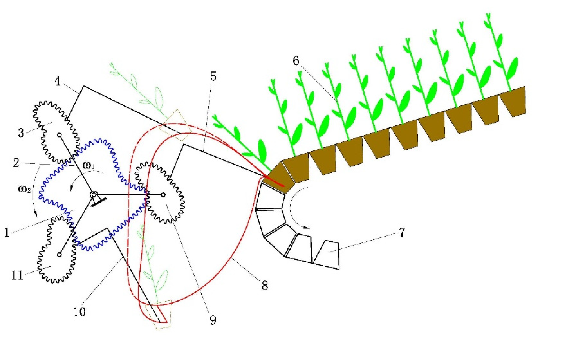
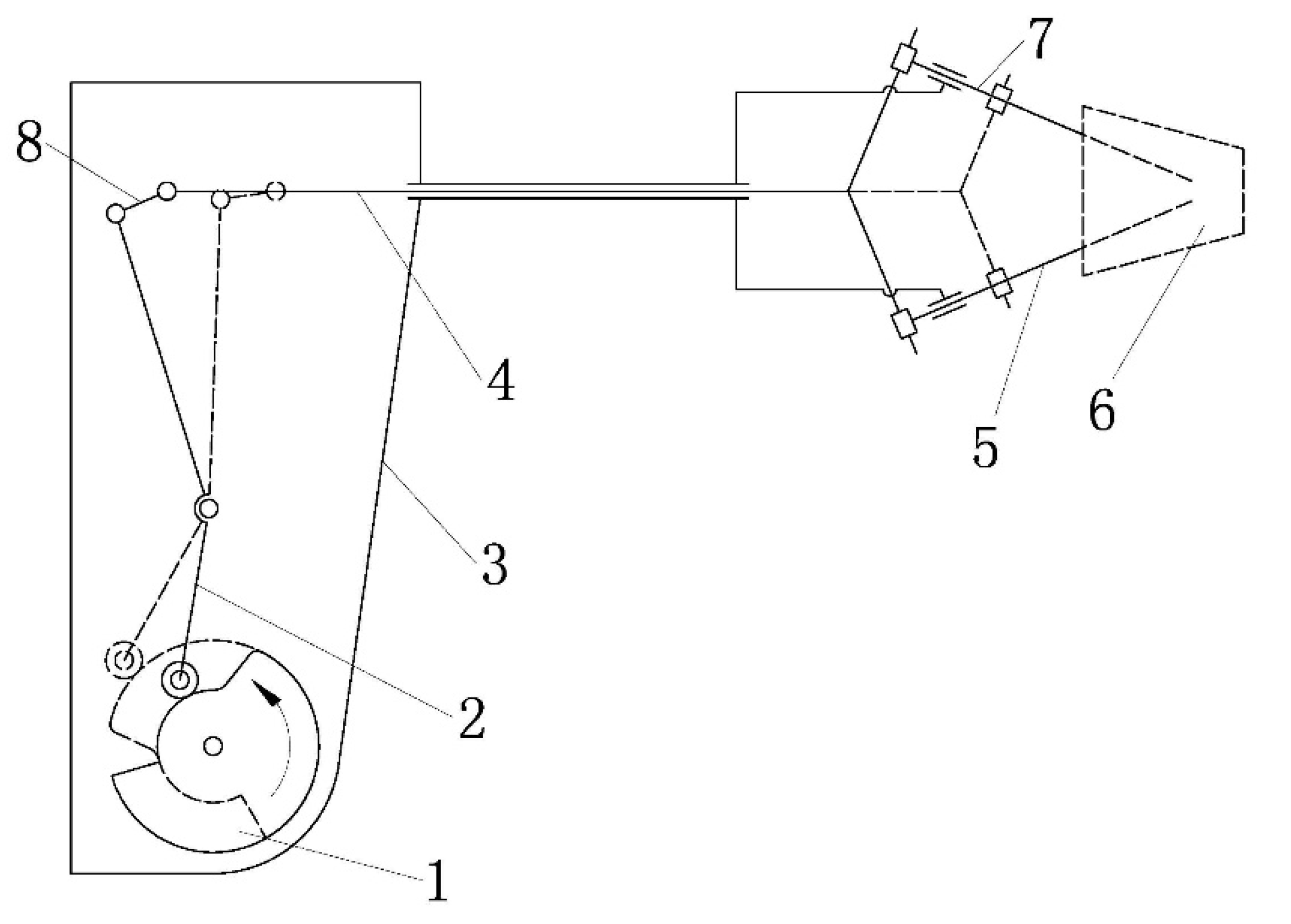
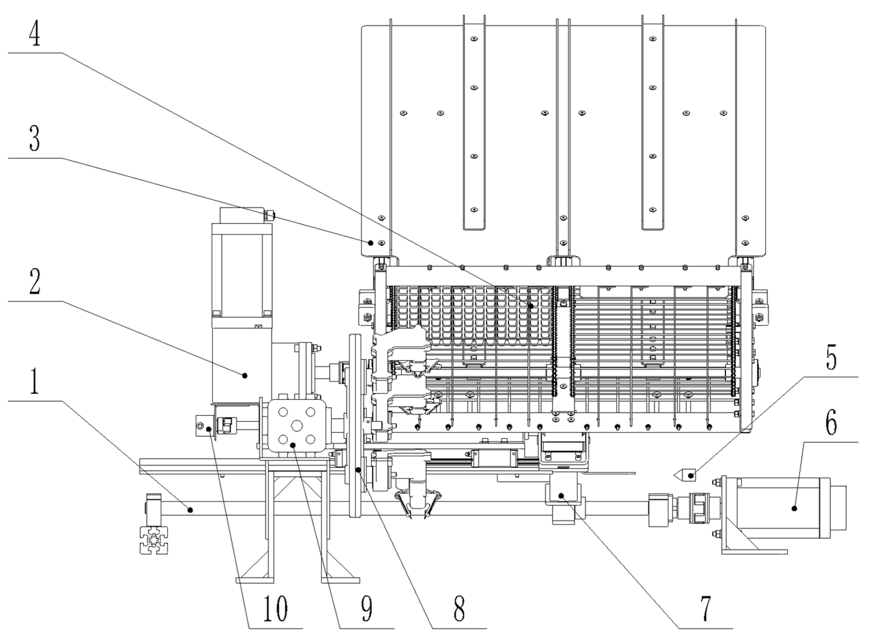
2.1. Composition and Working Principle of the SPM

The 2R open-chain mechanism only includes two rotating pairs, with a simple structure and flexible and convenient control. It is commonly used in the design of mechanisms such as transplanting mechanisms, biomimetic mechanisms, and robots. The hole plate SPM constrained by a differential non-circular gear system designed in this article consists of a 2R open-chain non-circular gear system and three seedling-picking arms. The 2R open-chain non-circular gear system consists of a non-circular center gear, a planetary carrier, and three non-circular planetary gears, and only includes two rotating pairs, as shown in Figure 1. The non-circular central gear and the planet carrier are coaxially hinged to the frame, and the three non-circular planet gears are each hinged to the planet carrier. The three picking arms are each fixed to one of the non-circular planet gears. During operation, the non-circular central gear and the planet carrier rotate counterclockwise at a certain speed. The three non-circular planet gears perform circular motions along with the planet carrier while also engaging in variable speed rotations relative to the planet carrier through their meshing with the non-circular central gear. This configuration allows the three picking arms, attached to the non-circular planet gears, to achieve the required seedling-picking trajectory and attitude. The pitch curve of the non-circular central gear is fitted using a closed Bezier curve, which can meet the principle of the non-sliding meshing of gears [30,31]. The single-stage transmission adopted in this design directly avoids the accumulation of backlash caused by multi-stage transmission.
The picking arm primarily consists of components such as a cam, a fork, a picking arm casing, a push rod, seedling needles, and a connecting rod, as shown in Figure 2. The picking arm casing is fixed to the non-circular planet gear, and the cam is fixed to the planet carrier. The fork is hinged inside the picking arm casing, forming a swing follower form of cam mechanism with the cam. The lower end of the fork contacts the cam, while the upper end is hinged to the connecting rod, the other end of which is hinged to the push rod. The front of the push rod is in a “Y” shape, with a pair of seedling needles symmetrically arranged on both sides. The seedling needles form a moving pair with the push rod and the shell of the seedling arm. During operation, the picking arm casing moves in a circular motion with the non-circular planet gear and also rotates at variable speeds relative to the planet carrier (cam). With the picking arm casing as a reference, the cam rotates counterclockwise at variable speeds relative to the picking arm casing, causing the selector fork to reciprocate within the picking arm casing. The upper end of the fork drives the push rod to perform reciprocal linear motion. Under the constraint of the moving pair, this movement enables the two seedling needles to extend and retract. When the push rod moves forward, the seedling needle slides inward along the “Y” shape of the push rod and moves inward relative to the shell of the seedling arm. The seedling needle is inserted into the chili substrate and the chili seedlings are taken out to achieve seedling retrieval. The two seedling needles are set at a certain angle (about 45 degrees) to each other. As the seedling needles extend and retract, they can perform the actions of clamping and pushing the seedlings. At the picking position, the two seedling needles extend (entering the seedling matrix of the plug tray) and clamp the crop seedlings in the tray (shown in dashed lines in the figure). At the feeding position, the two seedling needles retract (exiting the seedling matrix of the plug tray), releasing the crop seedlings and accomplishing the pushing action.

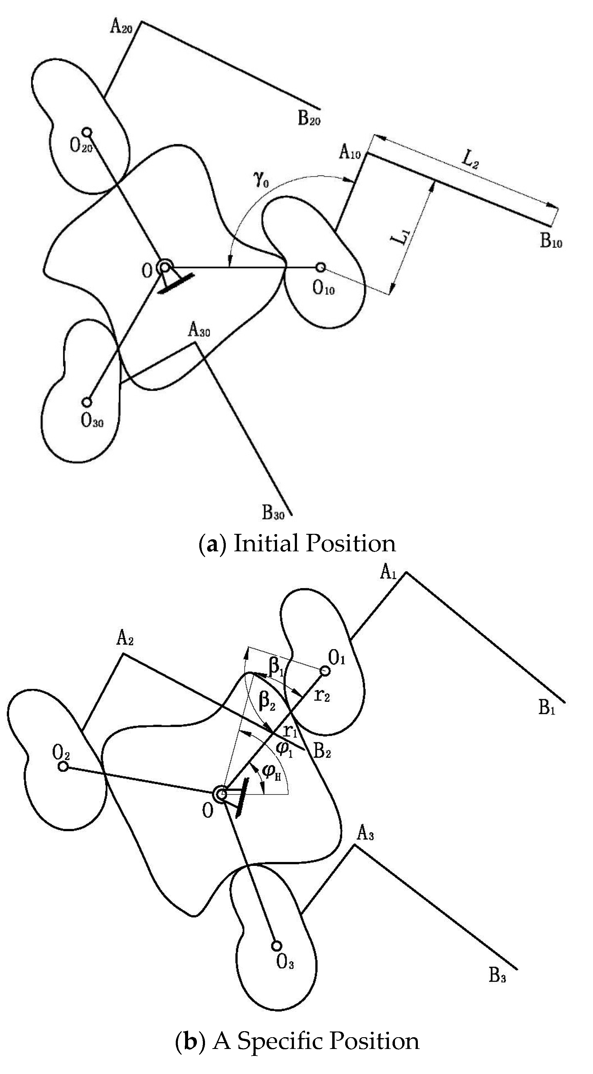
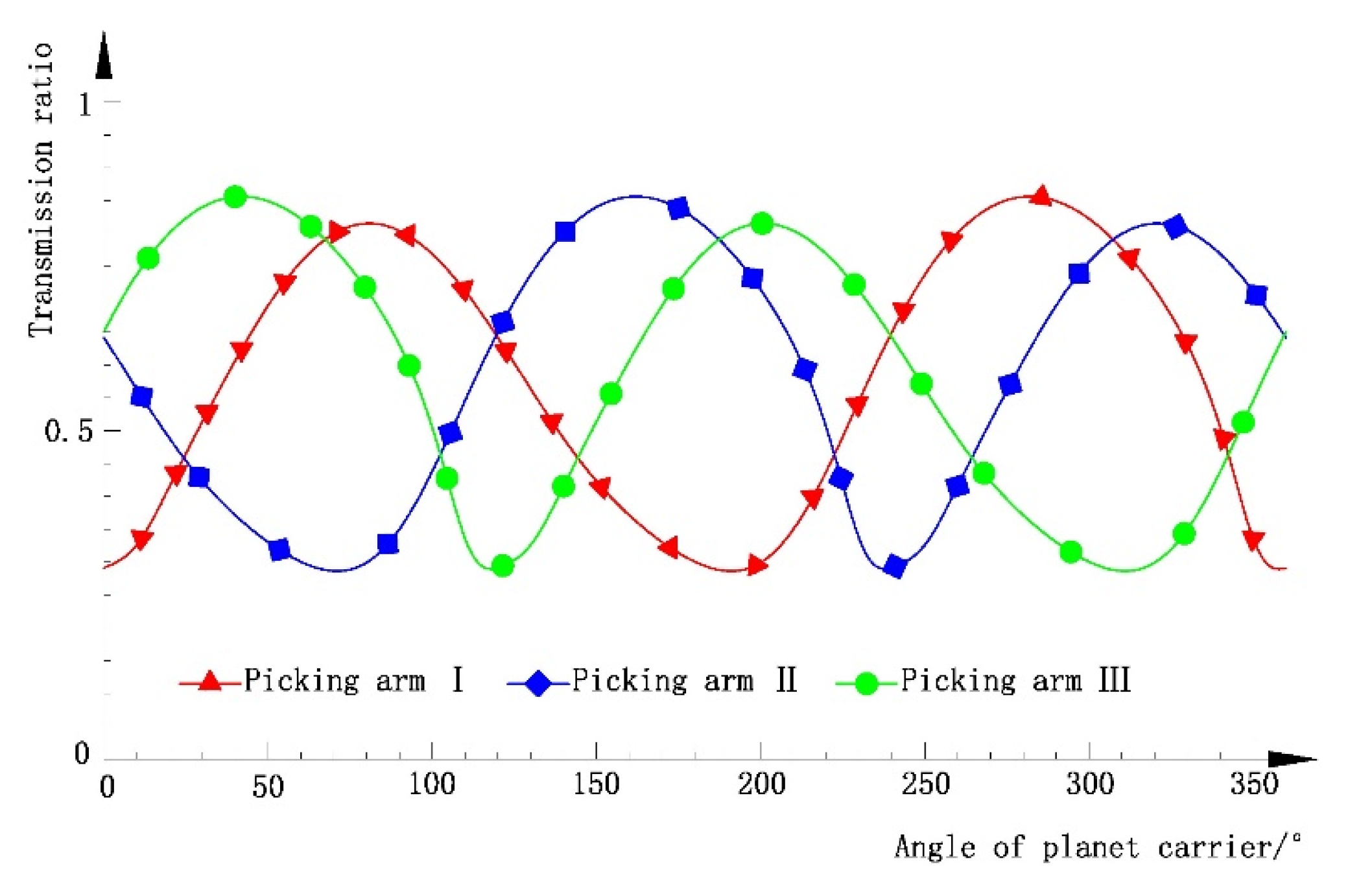
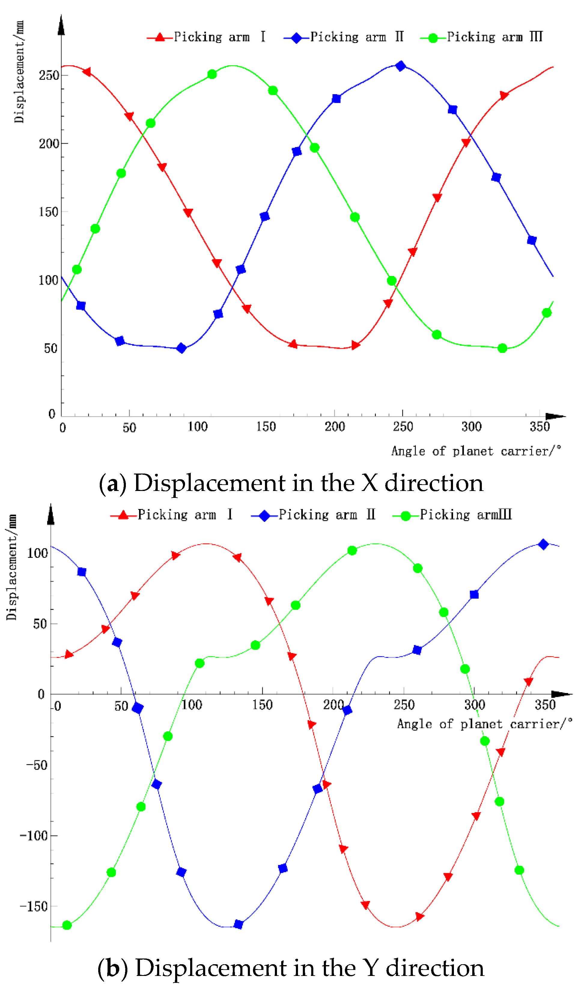
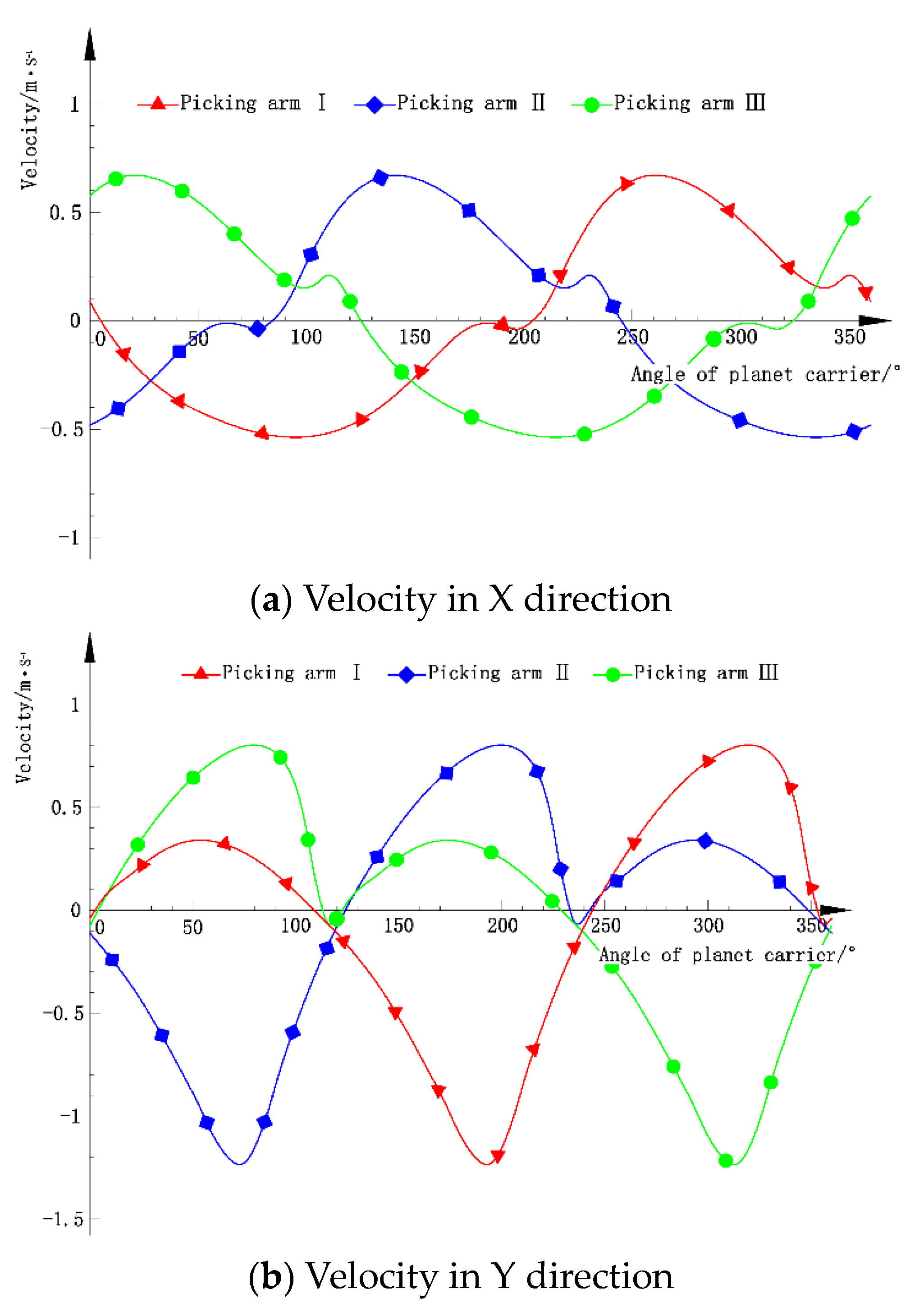
2.2. Kinematic Model of a 2R Open-Chain Mechanism Constrained by a Differential Non-Circular Gear Train

In the SPM constrained by a differential non-circular gear train, the motion laws of the three picking arms are the same, but their phase angles differ by 2 π / 3 each. This means that after the planet carrier rotates by 2 π / 3 , the position of Picking Arm I changes to that of Picking Arm II, and after another 2 π / 3 rotation, it changes to the position of Picking Arm III. Taking Picking Arm I as an example for analysis, the initial angular displacement of the planet carrier is 0 (see Figure 3a). When the planet carrier rotates counterclockwise by φ H , the non-circular central gear rotates counterclockwise by φ 1 (see Figure 3b).
The differential ratio between the non-circular central gear and the planet carrier is as follows:
i 1 H = φ 1 / φ H
The absolute displacement of the non-circular planet gear is as follows:
φ 2 = φ H β 1
where β 1 represents the relative angular displacement of the non-circular planet gear with respect to the planet carrier.
β 1 = 2 π β 2 2 π r 2 r 1 d θ
Here, r 1 and r 2 are the radii of the non-circular central gear profile and the non-circular planet gear profile at their respective meshing points; β 2 is the relative angular displacement of the non-circular central gear relative to the planet carrier.
β 2 = φ 1 φ H
Coordinates of the center of rotation for the non-circular planet gear are as follows:
O 1 x = O O 1 cos φ H O 1 Y = O O 1 sin φ H
Coordinates of the inflection point A1 on the picking arm are as follows:
A 1 x = O 1 x + L 1 cos φ 2 + γ 0 A 1 y = O 1 y + L 1 sin φ 2 + γ 0
Coordinates of the endpoint B1 of the picking arm are as follows:
B 1 x = A 1 x + L 2 cos φ 2 + γ 0 π 2 B 1 y = A 1 y + L 2 sin φ 2 + γ 0 π 2
Given a full rotation cycle of the planet carrier (known to be 2π), the coordinates of the endpoint of the picking arm can be calculated throughout a working cycle, thereby defining the trajectory of the seedling picking.

2.3. Optimization of SPM Parameters

The core of any fully automatic transplanting machine is its SPM, and the essence of this mechanism lies in its parameters. Optimizing these parameters represents a complex optimization challenge characterized by multi-parametric and multi-objective considerations that involve ambiguity and strong interdependencies. This optimization must account for both the agronomic requirements of plug seedling transplantation and the kinematic and dynamic performance of the mechanism. Traditional methods such as trial-and-error and weighted approaches are inadequate for the optimization of SPM parameters. This study, based on the kinematic model of the 2R open-chain mechanism constrained by a differential non-circular gear system, independently developed optimization design software for the SPM. Utilizing this software, a set of mechanism parameters that satisfy the requirements for plug seedling picking was established by using human–machine interaction optimization technology.

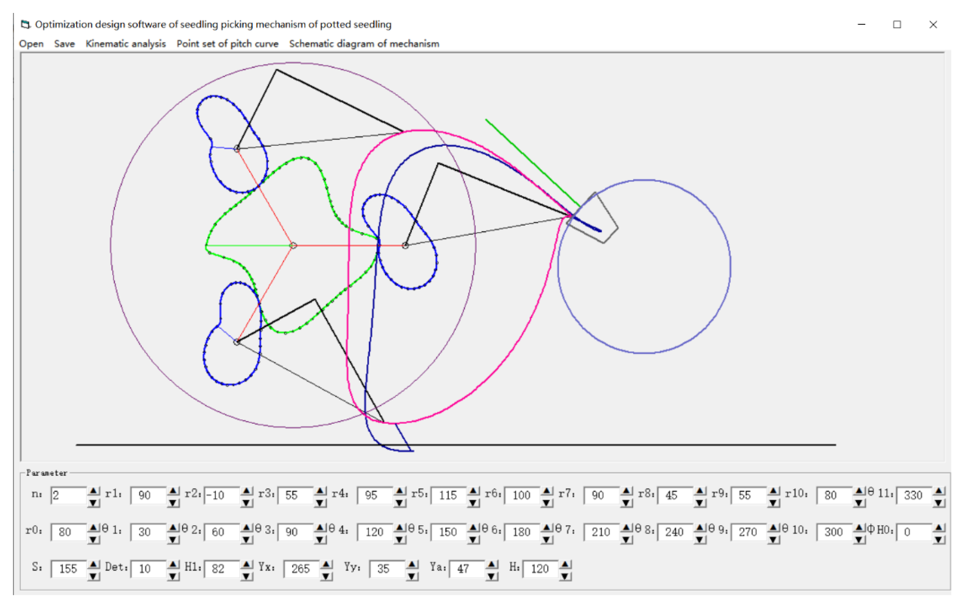
2.3.1. Development of Optimization Design Software and Parameter Optimization

Based on the kinematic model of the vegetable hole tray seedling-picking mechanism established in Section 2.2, this study developed an optimization design software for the seedling-picking mechanism, as shown in Figure 4. The software includes several parts, such as the menu bar, graphic display area, and parameter area. The parameter area includes all variable parameters of the seedling-picking mechanism. In the graphic display area, the software can display the working trajectory of the seedling-picking mechanism in real time based on the changes in the mechanism parameters, and can intuitively display the motion of the seedling-picking mechanism, including relative motion trajectory and absolute motion trajectory. Click the save button in the menu bar to save the parameters in the parameter area as a .dat format file; click the open button in the menu bar to open the saved .dat file and display the trajectory in the graphic display area; click on the node curve point set in the menu bar to save the node curve point set of non-circular center wheels in .dat format; click on the mechanism schematic in the menu bar to save the mechanism schematic of this transplanting mechanism in DWG format.
This study developed and utilized an SPM optimization design software, which took into account requirements such as angles for picking and feeding seedlings, the difference in angles, as well as the kinematic and dynamic performance issues like interference of the picking arm, whether the modulus of the non-circular gears is too small, and if there are abrupt changes in the non-circular profile curves. A human–machine interaction optimization method was used to derive a set of mechanism parameters that meet the seedling-picking requirements: r0 = 80 mm, r1 = 90 mm, θ1 = 30°, r2 = −10 mm, θ2 = 60°, r3 = 55 mm, θ3 = 90°, r4 = 95 mm, θ4 = 120°, r5 = 115 mm, θ5 = 150°, r6 = 100 mm, θ6 = 180°, r7 = 90 mm, θ7 = 210°, r8 = 45 mm, θ8 = 240°, r9 = 55 mm, θ9 = 270°, r10 = 80 mm, θ10 = 300°, θ11 = 330°, ΦH0 = 0°, S = 155 mm, Det = 10°, H1 = 82 mm, Yx = 265 mm, Yy = 35 mm, and Ya = 47°. In this set of parameters, ri (i = 0…10) are the radial coordinates of the control points on the profile curve of the non-circular central gear, θi (i = 1…11) are the angular coordinates of these points, ΦH0 is the initial angular displacement of the planet carrier, S is the distance from the center of rotation of the non-circular planet gear to the endpoint of the picking arm, Det is the initial mounting angle of the picking arm relative to the non-circular planet gear, H1 is the distance from the center of rotation of the non-circular planet gear to the push rod, (YX, YY) are the coordinates of the center of rotation of the plug tray, and Ya is the angle of the seedlings at the picking position. Under these parameters, the postures of the picking arm at critical positions and the working states of each picking arm during a cycle are shown in Table 1 and Table 2, respectively.
Under this set of parameters, the specific parameters of non-circular gears are shown in Table 1.
The variable transmission ratio between the non-circular central gear and the non-circular planet gears dictates the variable speed rotational law of the non-circular planet gears relative to the planet carrier, which in turn determines the trajectory and attitude of the picking arm. Under optimized parameters, the variable transmission ratios between the three non-circular planet gears and the non-circular central gear are as shown in Figure 5. The average transmission ratio between the non-circular central gear and the non-circular planet gears is 0.5, with the maximum instantaneous transmission ratio reaching 0.856 and the minimum instantaneous transmission ratio at 0.286. As the planet carrier rotates, within one cycle, the variable transmission ratio between the non-circular central gear and the non-circular planet gears features two peaks and two troughs, following a quadratic unequal amplitude transmission ratio motion law (Table 3).
Under optimized mechanism parameters, the displacement curve of the picking arm endpoint, as it rotates with the planet carrier, is shown in Figure 6. In the X direction, the maximum displacement of the picking arm endpoint is 256.94 mm, and the minimum displacement is 49.87 mm. In the Y direction, the maximum displacement of the picking arm endpoint is 106.49 mm, and the minimum displacement is −164.93 mm. The picking arm endpoint achieves the seedling-picking trajectory between the maximum and minimum displacements, picking seedlings at the trajectory point (256.92, 26.25) and feeding seedlings at the trajectory point (93.96, −164.93).
Under optimized parameters, the velocity curve of the picking arm endpoint is shown in Figure 7. In the X direction, the maximum velocity of the picking arm endpoint is 0.67 m/s, and the minimum velocity is −0.54 m/s. In the Y direction, the maximum velocity is 0.8 m s−1, and the minimum velocity is −1.23 m/s. During seedling picking, the velocity of the picking arm endpoint in the X direction is −0.015 m/s, and in the Y direction is −0.051 m/s, with a resultant velocity of 0.05 m/s. The angle between the resultant velocity direction and the growth direction of the crop seedlings is 30.59°. During seedling feeding, the velocity of the picking arm endpoint in the X direction is 0.616 m s−1 and in the Y direction is 0.018 m/s, with a resultant velocity of 0.617 m/s. The angle between the resultant velocity direction and the growth direction of the crop seedlings is 102.22°. When picking seedlings, the picking arm endpoint moves to the picking position at a slower speed, with a smaller angle relative to the growth direction of the crop seedlings, which can increase the success rate of picking and ensure the integrity of the seedling pot matrix. When feeding seedlings, the picking arm endpoint moves to the feeding position at a higher speed, with a larger angle relative to the growth direction of the crop seedlings, which can improve the success rate of pushing seedlings.

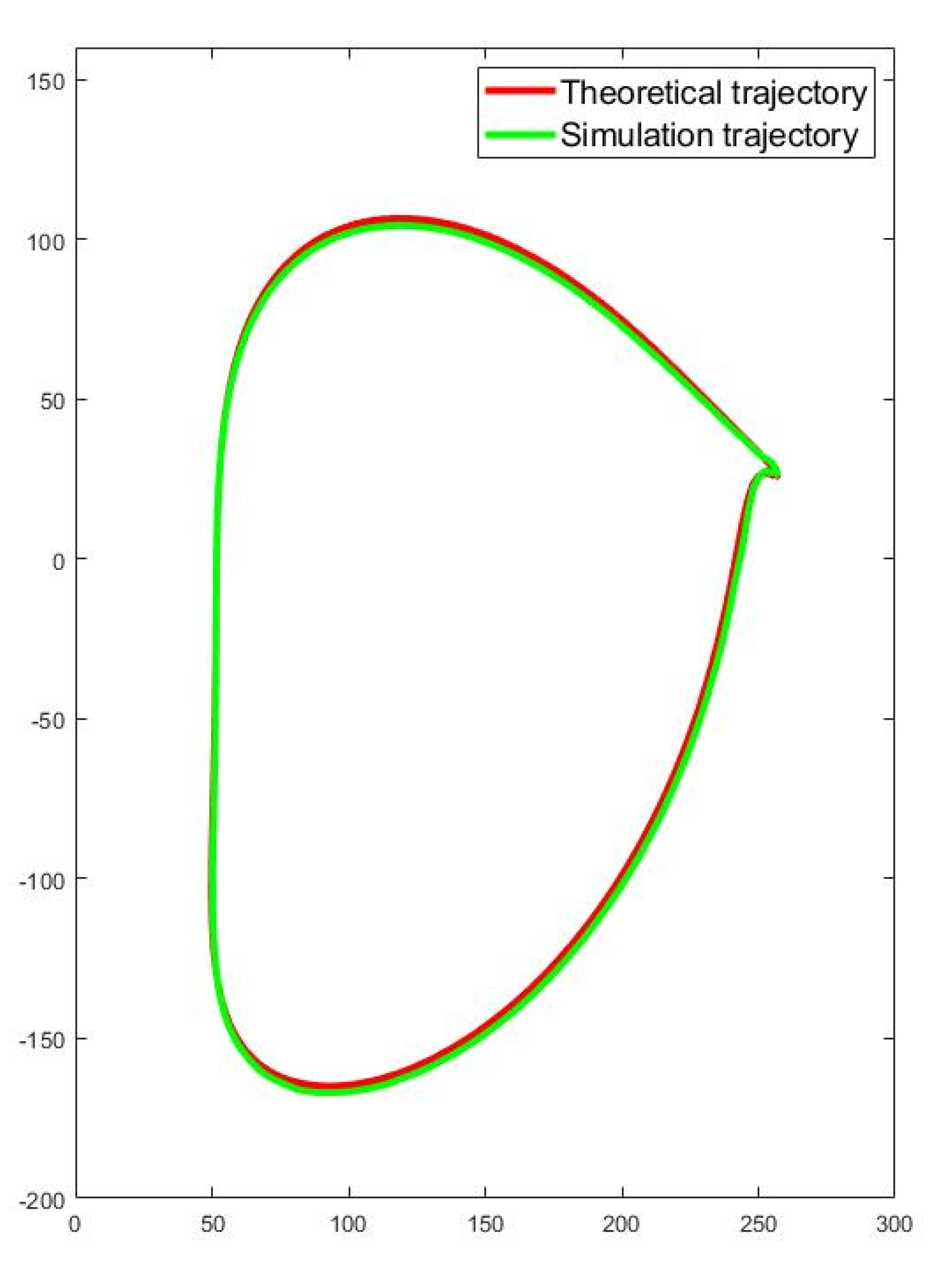
2.3.2. Seedling-Picking Trajectory Analysis

The working trajectory of the SPM is formed by the combined actions of the differential 2R non-circular gear system and the extension of the seedling needle, as shown in Figure 8. The differential non-circular gear system achieves the basic trajectory of the picking arm endpoint through the differential rotation between the non-circular central gear and the planet carrier, and the variable speed transmission between the non-circular central gear and the non-circular planet gears (shown in Figure 8a). Point Q represents the seedling-picking position, and point T represents the seedling feeding position. To enhance the seedling-picking success rate and ensure the integrity of the seedling pot matrix, this study designed a protruding seedling clamping device. At the picking position (point Q), the seedling needle extends into the seedling pot matrix to clamp the crop seedlings; at the feeding position (point T), the seedling needle retracts and exits the seedling pot matrix. The trajectory formed after the seedling needle extends is shown in Figure 8b, extending from point Q to retracting at point T, with the seedling needle maintaining the clamped state of the crop seedlings. The trajectory post-extension resembles the normal curve to the basic trajectory (from Q point to T point). By combining the basic trajectory with the extension trajectory, the working trajectory of the seedling needle endpoint can be obtained, as shown in Figure 8c. From the working trajectory of the seedling needle endpoint, it is evident that the SPM sequentially completes the processes of entering the seedling pot matrix to clamp seedlings, transporting the crop seedlings from the picking position to the feeding position, exiting the seedling pot matrix to push seedlings, and returning. This cycle enables continuous seedling picking.
Import the established 3D model of the SPM into ADAMS simulation software (Version: R2020), establish constraints, and apply drivers to obtain the basic trajectory of the seedling-picking arm endpoint (as shown in Figure 8d). Comparing Figure 8a and Figure 8d, it can be seen that the simulated trajectory is basically consistent with the theoretical trajectory. The speed ratio between the non-circular center wheel and the planetary carrier of this SPM is 3:2. When simulating in ADAMS, the speed of the non-circular center wheel is set to 20°/s, the speed of the planetary carrier is set to 30°/s, the simulation time is 18 s, and the number of steps is 360. From this, 360 coordinate points of the trajectory can be obtained and plotted in Matlab. It can be seen that the simulated trajectory basically coincides with the theoretical trajectory (as shown in Figure 9). Export the coordinate points and compare them with the 360 coordinate points of the theoretical trajectory to obtain the trajectory accuracy, as shown in Table 4 (choose any 12 points).
In the randomly selected points, the maximum deviation between the simulated trajectory and the theoretical trajectory is 3.1575 mm, the minimum deviation is 0.0276 mm, and the average deviation is 1.3938 mm. It can be considered that the simulated trajectory is basically coincident with the theoretical trajectory, which can meet the operational requirements of chili seedlings.

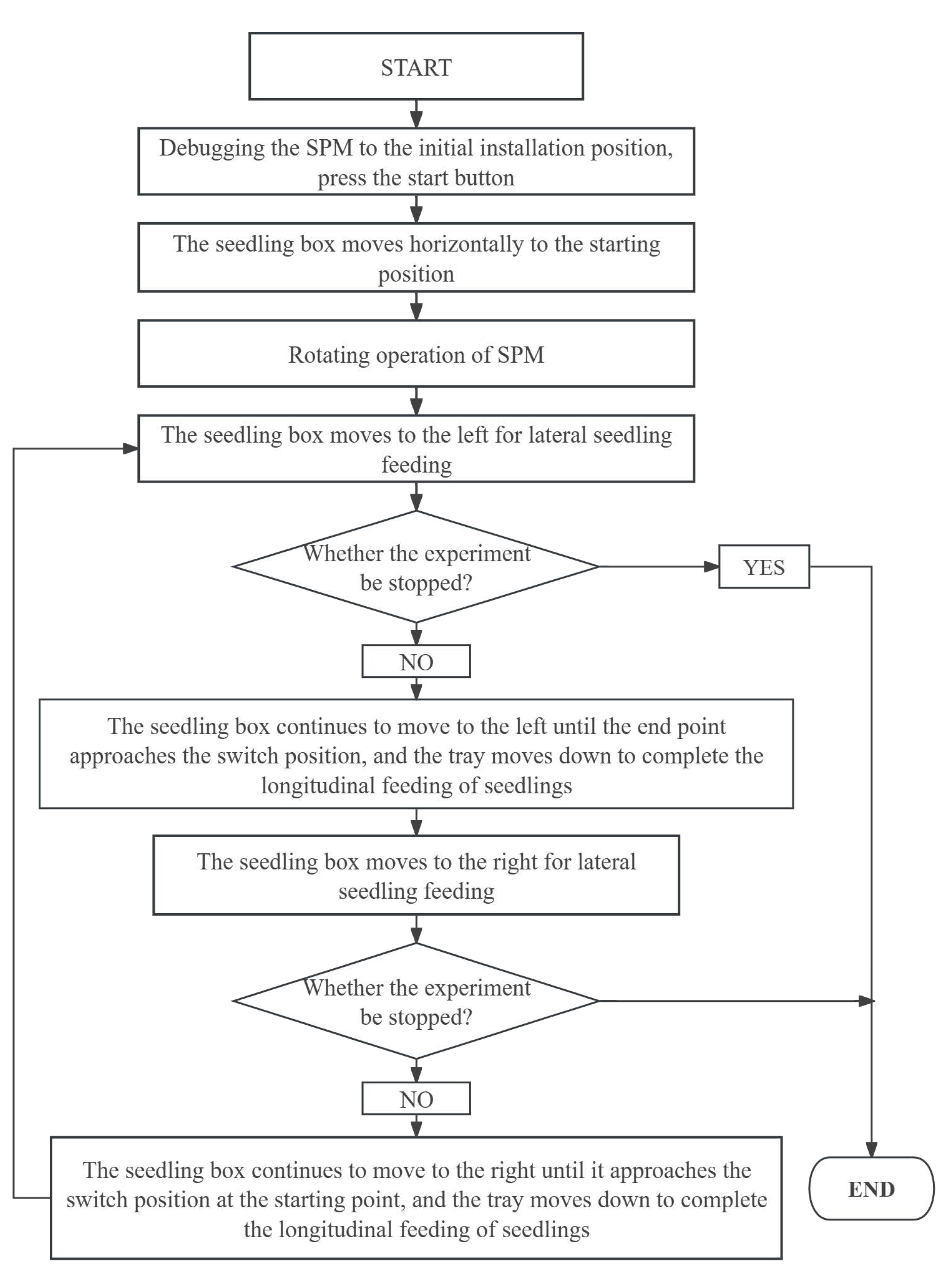
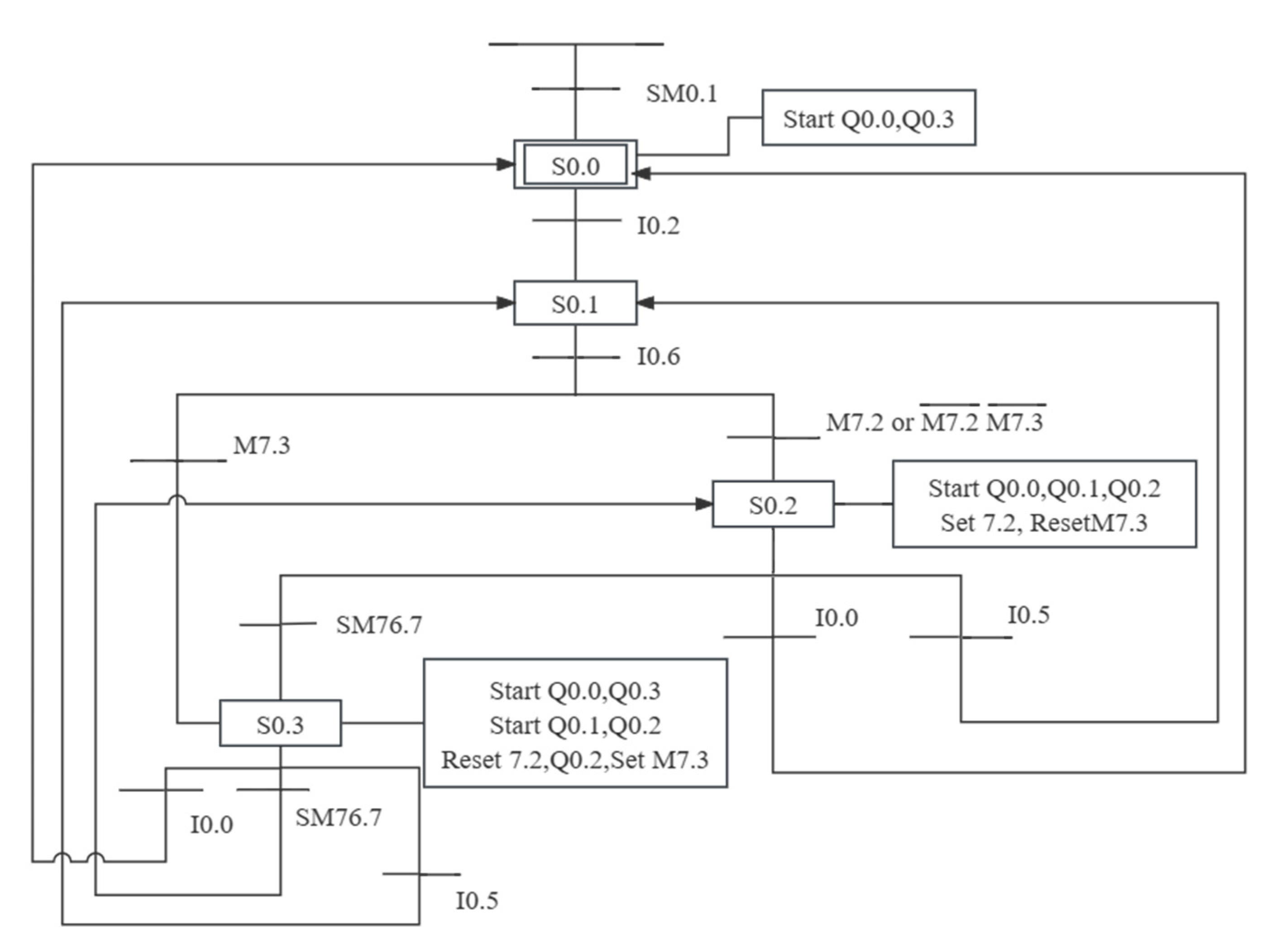
2.4. Design of the SPM Control System

For experimental trials under laboratory conditions, it is necessary to construct a test bench for the SPM and its corresponding control system. The test bench, under the operation of the control system, provides the required operational environment for the SPM, such as horizontal and vertical seedling feeding mechanisms, allowing for more accurate testing of the mechanism’s performance. A schematic of the test bench structure is shown in Figure 10, mainly consisting of a lead screw vertical stepper motor, a seedling box, a seedling tray, a horizontal stepper motor, a lead screw nut, a differential transmission box, a transplanting mechanism, an encoder, and a displacement sensor. Among these components, the lead screw nut is fixed to the seedling box, and the output shaft of the horizontal stepper motor is connected to the lead screw. As the horizontal stepper motor rotates, it drives the seedling box to move back and forth along the axis of the lead screw, thus facilitating horizontal seedling feeding; the vertical stepper motor is mounted on the side of the seedling box, driving the seedling tray to move downward, achieving vertical seedling feeding; the SPM is mounted on the differential transmission box for rotational seedling picking; the encoder is connected to the output shaft of the differential transmission box; and the displacement sensor is installed between the seedling box and the frame to limit and real-time adjust the speed and position of the seedling box’s horizontal movement.
This test bench is equipped with three motors: a lead screw vertical stepper motor, a horizontal stepper motor, and a variable frequency motor that drives the SPM. A PLC-based automatic control system was designed for this test bench, allowing it to perform automatic seedling picking through the composite motion of these three motors.
The automatic control logic flowchart is shown in Figure 11. When conducting the experiment, press the start button to activate the test bench. Initially, the horizontal stepper motor moves, driving the seedling box back to zero or the initial position. The initial position aligns the leftmost column of seed holes in the seedling box with the transplanting mechanism’s seedling clamps. Once the seedling box reaches this position, the transplanting mechanism starts rotating while the horizontal stepper motor moves the seedling box left. During this process, the transplanting mechanism repetitively performs the transplanting action. It is crucial to ensure that when the transplanting mechanism rotates to the seedling-picking point, the seedling clamps are precisely positioned in the middle of the seed hole. When the seedling box reaches the left limit, indicating that the row of seedlings has been fully transplanted, the end position switch sends a signal, the vertical stepper motor rotates a fixed angle to carry out vertical seedling feeding, and then the horizontal stepper motor moves the seedling box to the right to perform horizontal seedling feeding again. When the seedling box reaches the right limit, indicating that the row has been fully transplanted, the start position switch sends a signal, the vertical stepper motor rotates a fixed angle to perform another cycle of vertical seedling feeding, and the horizontal stepper motor drives the seedling box left for another round of horizontal seedling feeding. This cycle repeats continuously, with each mechanism operating according to the pre-set transplanting process. After pressing the pause button, all mechanisms on the test bench stop. Pressing the start button again resumes the operation from where it stopped. Pressing the emergency stop button immediately halts all mechanisms. After releasing the emergency stop and pressing the start button again, the horizontal stepper motor first moves, searching for the starting position of the seedling box. Once the seedling box reaches its starting position, it coordinates with the transplanting mechanism to continue the transplanting action according to the automatic operation program.
The automatic operation program must be written according to the sequential actions of each mechanism, following a specific logical order. Therefore, analyzing the actions of each executing mechanism and the input signals during the transplanting experiment process allows for the determination of the PLC’s I/O point allocation. A total of 6 input points and 5 output points are required. The specific I/O allocation is detailed in Table 5.
Based on the I/O allocation provided in Table 5, a Sequential Function Chart (SFC) is drawn as shown in Figure 12.
In the entire control system, the longitudinal seedling feeding mechanism is controlled by a stepper motor in both forward and reverse directions, and the forward and reverse rotation of the motor cannot be completed instantaneously. And the seedling-picking mechanism keeps rotating at a constant speed, which will lead to seedling-picking errors. Therefore, this article connects an encoder at the output shaft end of the differential transmission box to measure the real-time speed of the transplanting mechanism. Install a displacement sensor between the rice box and the frame to limit and adjust the lateral movement of the rice box in real time. The specific settings are shown in Figure 9.
This seedling-picking mechanism rotates once, takes three seedlings, and the control program is targeted at the seedling tray with a spacing of 40 mm between the seedling holes. Therefore, the transplanting mechanism rotates 360 degrees, the seedling box moves 120 mm, the transplanting mechanism rotates 540 degrees, and the seedling box moves 180 mm. Therefore, the ratio of total displacement to total rotation angle is equal to 3. Set an error value of positive and negative 0.01, and obtain a theoretical ratio range of 2.99–3.01 for a single arm. If the ratio interval exceeds 3.01, accelerate the movement speed of the seedling box or reduce the rotation angle of the transplanting mechanism. If the ratio range is below 2.99, reduce the movement speed of the seedling box or accelerate the rotation angle of the transplanting mechanism. By setting the error range, errors can be eliminated within an effective range to ensure the accuracy of seedling retrieval.

3. Results and Discussion

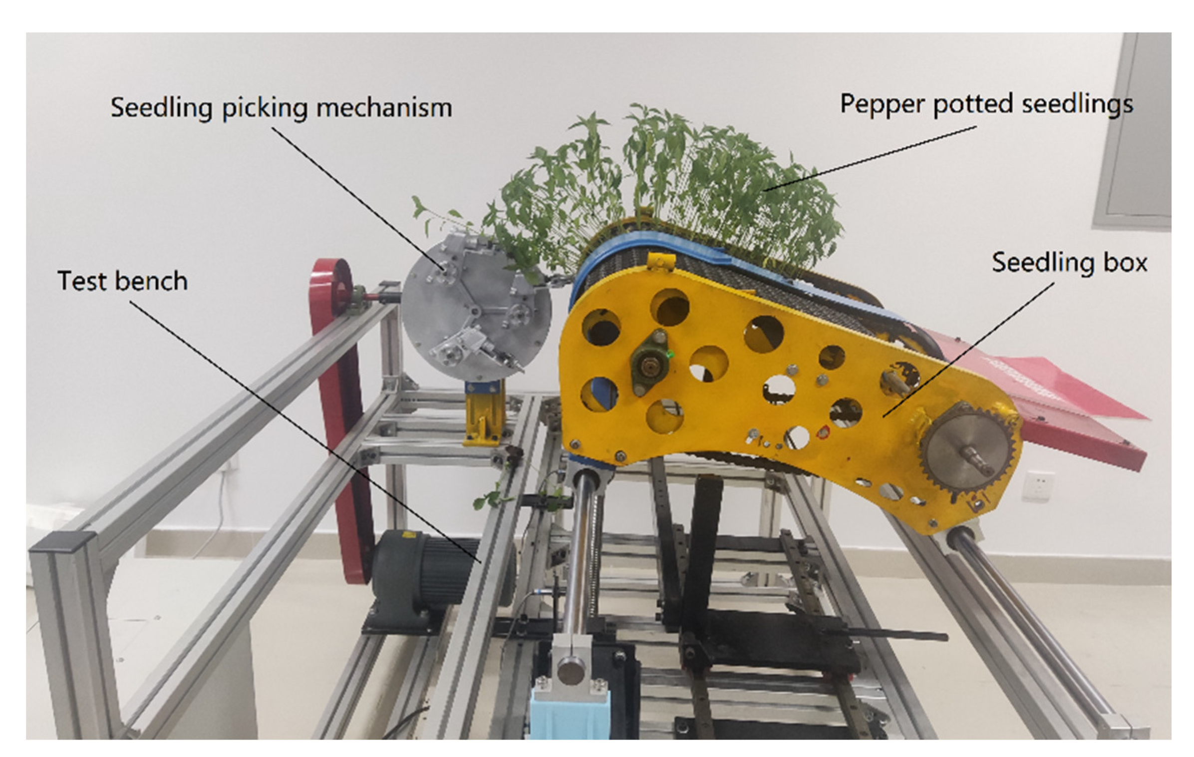
3.1. Attitude Verification Experiment

Based on the optimized mechanical parameters, the structural design of the SPM was completed, and a posture verification experiment was conducted on the SPM test bench. The experiment demonstrated that the designed SPM could successively perform processes such as extending the seedling needle, transporting, retracting the seedling needle, and returning. High-speed camera footage was analyzed to capture the seedling-picking trajectory and attitude, which were then compared with the trajectory and attitude calculations from the optimization design software. This comparison confirmed a high degree of consistency, mutually verifying the accuracy of both the optimization design software and the test bench experiment. The equipment used in this experiment was the I-SPEED3 high-speed camera. I-SPEED3 is a high-speed video camera launched by i-SPEED TR, Olympus Corporation, Tokyo, Japan. It is a microscope high-speed camera with a 1280 × 1024-pixel sensor capable of achieving a frequency range of 24 fps to 15,000 fps, ultra-high sensitivity, with a 1 μs full field exposure electronic shutter and a control panel CDU for remote device control (Figure 13).

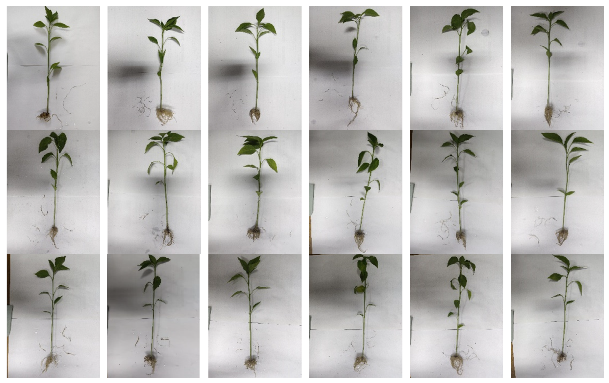
3.2. Seedling Picking Performance Test

The seedling picking performance test was conducted using pepper plug seedlings as the transplant subjects, as shown in Figure 14. The experiment utilized the pepper variety “line pepper 8819”, which was cultivated in a specialized nursery matrix for fruits and vegetables (mainly consisting of peat, vermiculite, and perlite). At the time of the experiment, the seedlings were 47 days old, with an average height of 176.5 mm and an average stem diameter of 3 mm. The matrix’s relative moisture content was 45%, and the volumetric weight was 0.3273 ± 0.01 g·cm−3; the seedlings met the national technical standards for transplanting chili seedlings. The seedling tray used in the experiment was a 128-cell plastic tray (8 cells across and 16 cells down) with a pyramidal hole shape; the top of each cell was a 30 mm × 30 mm square, narrowing down to a 15 mm × 15 mm square at the bottom, with a depth of 40 mm. During the test, the SPM operated at a uniform speed, with the seedling box intermittently supplying seedlings horizontally and vertically. The test demonstrated that the three picking arms of the SPM could move sequentially according to the picking trajectory and attitude, alternately completing the clamping and feeding actions.
The key indicators for evaluating the quality of seedling picking are the integrity of the hole tray seedling substrate and the damage rate to seedlings. The SPM designed in this study uses seedling needles to grasp and lift the seedling matrix, thereby reducing the degree of damage to the seedling substrate and avoiding damage to the crop stems and leaves. A complete substrate shortens the seedling growth period and increases the seedling rate after transplanting. The roots are the most crucial organ for pepper plants to absorb water and nutrients. Damage to the roots during growth can not only affect the plant’s ability to absorb water and nutrients but also significantly increase the risk of disease in pepper plants. Pepper plants have limited roots and poor regenerative ability after root breakage.
The experiment analyzed the substrate and root damage of pepper plug seedlings using the protruding seedling-picking method, and the soil matrices of the extracted hole seedlings were intact, and some of the extracted plug seedlings were washed as shown in Figure 15. The average length of the main roots of the experimental pepper plug seedlings was 34.5 mm, with no damage to the main roots. The average length of lateral root damage was 190.3 mm, with a lateral root damage rate of about 15.7%, effectively reducing the recovery period after transplantation and ensuring the success rate of seedlings after planting.
Based on the team’s years of transplanting experience, the root growth of chili seedlings mainly relies on the main root, while the influence of lateral roots on seedling growth is relatively small. Through the analysis of experimental data, it was found that although there was some degree of damage to the lateral roots of pepper seedlings at different seedling extraction rates, the damage rate was within an acceptable range. Compared with other seedling-picking mechanisms, the seedling-picking device used in this study can maintain a high degree of integrity of the plug seedling substrate and significantly reduce the damage rate of lateral roots. Therefore, the design of this seedling-picking mechanism not only meets the expected design requirements but also meets the agronomic needs during the transplanting process of chili seedlings.

4. Conclusions

(1) This study proposed a design scheme for a plug SPM constrained by a differential non-circular gear train. By using a single-stage non-circular gear transmission to control the motion laws of the picking arm, it avoids the issues of backlash accumulation caused by multi-stage variable speed transmissions. Theoretically, it can replicate any complex seedling-picking trajectory and attitude. By constraining the movement of the picking arm with a differential non-circular gear train, the design achieves high transmission efficiency and flexibility. This approach enhances the precision of replicating specific seedling-picking trajectories and attitudes, providing valuable references and insights for the design of SPMs.
(2) This research established a kinematic model for a differential 2R open-chain non-circular gear train and developed SPM optimization software (initial version) based on kinematic theory. This software can solve the complex problem of multi-parameter and multi-objective optimization for SPMs, significantly reducing the time required for mechanical parameter optimization. The design theories and methods presented here can be applied to other mechanism optimization designs, holding significant universal importance in the field of mechanisms.
(3) A control system for the SPM test bench was established using PLC control technology. By controlling the relationships between the speeds of the SPM motor, the horizontal stepper motor, and the vertical stepper motor with the PLC, it ensures that each transplanting arm accurately picks seedlings from the plug tray at the designated picking positions and performs the planting actions correctly.
(4) The plug SPM, constrained by a differential non-circular gear system, utilizes a protruding clamping method. Building on the basic trajectory, the clamping device extends at the picking point and enters the seedling substrate to perform a reliable clamping action, ensuring the integrity of the potted seedling matrix. Additionally, the smooth transition of the basic trajectory enhances the dynamic characteristics of the non-circular gear system.
(5) Using pepper plug seedlings as the transplant subjects, seedling-picking performance tests show that the designed SPM can successively execute the processes of probing and clamping seedlings, transporting, retracting, pushing seedlings, and returning. The seedling picking is precise and reliable. Following the seedling picking, no damage occurred to the main roots, while the lateral roots experienced an average breakage of 190.3 mm, resulting in a damage rate of 15.7%.

Author Contributions

M.Z. provides project management and financial support; T.X. conducts software development, algorithm optimization, and article writing; G.W., H.D., S.Y. and Z.W. carried out structural design and virtual simulation. All authors have read and agreed to the published version of the manuscript.

Funding

This study was financially supported by the Key R&D Plan of Zhenjiang City—Modern Agriculture (Grant No. NY2023003), Jiangsu Agriculture Science and Technology Innovation Fund (Grant No. CX(22)3089), China Postdoctoral Science Foundation (Grant No. 2021M691315), National Natural Science Foundation of China (Grant No. 52005221), Natural Science Foundation of Jiangsu Province (Grant No. BK20200897), Key Laboratory of Modern Agricultural Equipment and Technology (Jiangsu University), High-Tech Key Laboratory of Agricultural Equipment and Intelligence of Jiangsu Province, and A Project Funded by the Priority Academic Program Development of Jiangsu Higher Education Institutions (Grant No. PAPD 2023-87).

Data Availability Statement

The data presented in this study are available on request from the corresponding author. The data are not publicly available due to laboratory data privacy.

Conflicts of Interest

The authors declare no competing or financial interests.

References

  1. Zhao, X.; Guo, J.; Li, K.; Dai, L.; Chen, J. Optimal design and experiment of 2-DoF five-bar mechanism for flower seedling transplanting. Comput. Electron. Agric. 2020, 178, 105746. [Google Scholar] [CrossRef]
  2. Jin, X.; Li, S.; Yang, X.; Sun, X.; Yan, H.; Wu, J. Analysis and Parameter Optimization for Vegetable Plug Seedling Pick-up Mechanism. Trans. Chin. Soc. Agric. Mach. 2013, 44, 1–6, (In Chinese with English Abstract). [Google Scholar]
  3. Cui, W.; Fang, X.; Zhao, L.; Song, J.; Lin, J.; Dong, X. Structural Optimization and Experimental Verification of Geared Five-bar Linkage Seedling Pick-up Device. Trans. Chin. Soc. Agric. Mach. 2013, 44, 74–77, (In Chinese with English Abstract). [Google Scholar]
  4. Xu, L.; Zhang, T.; Shi, Z. Design on the Picking Seedling Machinery in the Maize Auto-transplanter. J. China Agric. Univ. 2000, 5, 58–60, (In Chinese with English Abstract). [Google Scholar]
  5. Yue, R.; Hu, J.; Liu, Y.; Yao, M.; Zhang, T.; Shi, J. Design and Working Parameter Optimization of Pneumatic Reciprocating Seedling-Picking Device of Automatic Transplanter. Agriculture 2022, 12, 1989. [Google Scholar] [CrossRef]
  6. Sharma, A.; Khar, S. Design and development of a vegetable plug seedling transplanting mechanism for a semi-automatic transplanter. Sci. Hortic. 2024, 326, 112773. [Google Scholar] [CrossRef]
  7. Dang, Y.; Jin, X.; Li, H.; Wang, J.; Lu, Y.; Ding, B.; Li, X. Design of single-degree-of-freedom four-bar seedling-taking and throwing manipulator. Trans. Chin. Soc. Agric. Eng. 2019, 35, 39–47, (In Chinese with English Abstract). [Google Scholar]
  8. Li, H.; Cao, W.; Li, S.; Fu, W.; Liu, K. Kinematic analysis and test on automatic pick-up mechanism for chili plug seedling. Trans. Chin. Soc. Agric. Eng. 2015, 31, 20–27, (In Chinese with English Abstract). [Google Scholar]
  9. Mao, H.; Ma, G.; Han, L.; Hu, J.; Gao, F.; Liu, Y. A whole row automatic pick-up device using air force to blow out vegetable plug seedlings. Span. J. Agric. Res. 2021, 18, e0211. [Google Scholar] [CrossRef]
  10. Han, L.; Mao, H.; Hu, J.; Xu, J.; Zhao, Z.; Ma, G. Design and test of combined pick-up device for automatic and precise transplanting of vegetable plug seedlings. Trans. Soc. Agric. Eng. 2015, 31 (Suppl. S2), 17–23. (In English) [Google Scholar]
  11. Han, L.; Mao, H.; Hu, J.; Kumi, F. Development of a riding-type fully automatic transplanter for vegetable plug seedlings. Span. J. Agric. Res. 2019, 17, e0205. [Google Scholar] [CrossRef]
  12. Han, L.; Mo, M.; Ma, H.; Kumi, F.; Mao, H. Design and Test of a Lateral-Approaching and Horizontal-Pushing Transplanting Manipulator for Greenhouse Seedlings. Appl. Eng. Agric. 2023, 39, 325–338. [Google Scholar] [CrossRef]
  13. Gao, X.; Quan, W.; Sun, S.; Xiao, M. Design and test of a cam for the plug seedling pick-up mechanism with sector gear. J. Hunan Agric. Univ. (Nat. Sci.) 2014, 40, 431–434, (In Chinese with English Abstract). [Google Scholar]
  14. Jia, B.; Ye, M.; Zhai, X.; Han, L.; Lu, J. Design and Tests of Cam—Link Combination Pick—Up Device for Vegetable Transplanters. J. Agric. Mech. Res. 2019, 41, 78–82, (In Chinese with English Abstract). [Google Scholar]
  15. Bae, K.-Y.; Yang, Y.-S. Design of a non-circular planetary-gear-train system to generate an optimal trajectory in a rice transplanter. J. Eng. Des. 2007, 18, 361–372. [Google Scholar] [CrossRef]
  16. Tong, Z.; Yu, G.; Zhao, X.; Liu, P.; Ye, B. Design of Vegetable Pot Seedling Pick-up Mechanism with Planetary Gear Train. Chin. J. Mech. Eng. 2020, 33, 63. [Google Scholar] [CrossRef]
  17. Xue, X.; Li, L.; Xu, C.; Li, E.; Wang, Y. Optimized design and experiment of a fully automated potted cotton seedling transplanting mechanism. Int. J. Agric. Biol. Eng. 2020, 13, 111–117. [Google Scholar] [CrossRef]
  18. Iqbal, M.Z.; Islam, M.N.; Chowdhury, M.; Islam, S.; Park, T.; Kim, Y.-J.; Chung, S.-O. Working Speed Analysis of the Gear-Driven Dibbling Mechanism of a 2.6 kW Walking-Type Automatic Pepper Transplanter. Machines 2021, 9, 6. [Google Scholar] [CrossRef]
  19. Iqbal, M.Z.; Islam, M.N.; Ali, M.; Kabir, M.S.N.; Park, T.; Kang, T.G.; Park, K.S.; Chung, S.O. Kinematic analysis of a hopper-type dibbling mechanism for a 2.6 kW two-row pepper transplanter. J. Mech. Sci. Technol. 2021, 35, 2605–2614. [Google Scholar] [CrossRef]
  20. Sun, L.; Shen, J.; Zhou, Y.; Ye, Z.; Yu, G.; Wu, C. Design of non-circular gear linkage combination driving type vegetable pot seedling transplanting mechanism. Trans. Chin. Soc. Agric. Eng. 2019, 35, 26–33, (In Chinese with English Abstract). [Google Scholar]
  21. Sun, L.; Hu, Y.; Xing, Z.; Yu, G.; Yu, Y. Motion Synthesis of Rotary Pot Seedling Transplanting Mechanism Based on Approximate Multi-pose. Trans. Chin. Soc. Agric. Mach. 2020, 51, 103–111, (In Chinese with English Abstract). [Google Scholar]
  22. Tong, J.; Yu, G.; Zhu, Y.; Ye, B.; Zheng, C.; Huang, J. Design and Experiment of Three-arms Rotary Vegetable Plug Seedling Pick-up Mechanism. Trans. Chin. Soc. Agric. Mach. 2019, 50, 113–121, (In Chinese with English Abstract). [Google Scholar]
  23. Zhao, X.; Shen, M.; Chen, J.; Dai, L. Kinematic analysis and virtual experiment of rotary pick-up mechanism on cotton transplanter. Trans. Chin. Soc. Agric. Eng. 2014, 30, 13–20, (In Chinese with English Abstract). [Google Scholar]
  24. Zhao, X.; Ma, X.; Liao, H.; Xiong, Y.; Xu, Y.; Chen, J. Design of flower transplanting mechanisms based on double planet carrier non-circular gear train with complete rotation kinematic pair. Int. J. Agric. Biol. Eng. 2022, 15, 9–15. [Google Scholar] [CrossRef]
  25. Zhou, M.; Shan, Y.; Xue, X.; Yin, D. Theoretical analysis and development of a mechanism with punching device for transplanting potted vegetable seedlings. Int. J. Agric. Biol. Eng. 2020, 13, 85–92. [Google Scholar] [CrossRef]
  26. Zhou, M.; Sun, H.; Xu, X.; Yang, J.; Wang, G.; Wei, Z.; Xu, T.; Yin, J. Study on the Method and Mechanism of Seedling Picking for Pepper (Capsicum annuum L.) Plug Seedlings. Agriculture 2023, 14, 11. [Google Scholar] [CrossRef]
  27. Zhou, M.; Yu, G.; Zhao, Y.; Hu, H.; Liao, Z.; Zhao, X. Parameter optimization and test on pick-up mechanism of planetary gear train with ellipse gears for vegetable plug seedling. Trans. Chin. Soc. Agric. Eng. 2014, 30, 13–21, (In Chinese with English Abstract). [Google Scholar]
  28. Yu, G.; Yu, T.; Ye, B.; Hu, H.; Wang, L. Design of a Rotary Plug Seedling Pick-up Mechanism. J. Mech. Eng. 2015, 51, 67–76, (In Chinese with English Abstract). [Google Scholar]
  29. Ye, B.; Zeng, G.; Deng, B.; Yang, C.; Liu, J.; Yu, G. Design and tests of a rotary plug seedling pick-up mechanism for vegetable automatic transplanter. Int. J. Agric. Biol. Eng. 2020, 13, 70–78. [Google Scholar] [CrossRef]
  30. Riaza, H.; Foix, S.; Nebot, L. The synthesis of an N-Lobe noncircular gear using Bezier and B-Spline Nonparametric curves in the design of its displacement law. J. Mech. Des. 2007, 129, 981–985. [Google Scholar]
  31. Zhou, M.; Yang, Y.; Wei, M.; Yin, D. Method for generating non-circular gear with addendum modification and its application in transplanting mechanism. Int. J. Agric. Biol. Eng. 2020, 13, 68–75. [Google Scholar] [CrossRef]
Figure 1. Composition diagram of the SPM. 1. Non-circular central gear, 2. planet carrier, 3. Non-circular Planet Gear II, 4. Picking Arm II, 5. Picking Arm I, 6. seedling, 7. plug tray, 8. trajectory, 9. Non-circular Planet Gear I, 10. Picking Arm III, 11. Non-circular Planet Gear III.
Agriculture 14 01576 g001
Figure 2. Structure of the picking arm. 1. Cam, 2. fork, 3. picking arm casing, 4. push rod, 5. seedling needle I, 6. plug tray, 7. Seedling Needle II, 8. connecting rod.
Agriculture 14 01576 g002
Figure 3. Kinematic analysis diagram of the SPM.
Agriculture 14 01576 g003
Figure 4. Optimization design software of SPM.
Agriculture 14 01576 g004
Figure 5. Variable Speed Transmission Ratio Curve.
Agriculture 14 01576 g005
Figure 6. Seedling-Picking Arm Displacement Curve.
Agriculture 14 01576 g006
Figure 7. Seedling-Picking Arm Speed Curve.
Agriculture 14 01576 g007
Figure 8. Seedling picking trajectory diagram.
Agriculture 14 01576 g008
Figure 9. Comparison between simulated trajectory and theoretical trajectory.
Agriculture 14 01576 g009
Figure 10. Schematic diagram of the test bench structure. 1. Lead screw, 2. vertical stepper motor, 3. seedling box, 4. seedling tray, 5. displacement sensor, 6. horizontal stepper motor, 7. lead screw nut, 8. seedling picking mechanism, 9. differential transmission box, 10. encoder.
Agriculture 14 01576 g010
Figure 11. Automatic control logic flowchart.
Agriculture 14 01576 g011
Figure 12. Sequential function chart of the automatic control program.
Agriculture 14 01576 g012
Figure 13. Seedling picking trajectory verification.
Agriculture 14 01576 g013
Figure 14. Test bench seedling picking experiment.
Agriculture 14 01576 g014
Figure 15. Root damage analysis diagram.
Agriculture 14 01576 g015
Table 1. Non-circular gear parameters.
ModuleTooth NumberCenter DistancePressure
Angle
Tooth WidthTooth Top Height CoefficientTop Clearance Coefficient
2.402332.0000103.282720.000010.00001.00000.2500
Table 2. Attitude of the seedling picking arm.
Picking AngleFeed AngleAngle DifferenceProtrude LengthAngle between Picking Arm and SeedlingAngle of Seedling Needles
−26.22°−59.34°−33.12°30 mm16.78°46°
Table 3. Corresponding planetary carrier angles for the working states of the seedling picking arms.
Picking Arm IPicking Arm IIPicking Arm III
Picking246°126°
Feeding245°125°
Table 4. Comparison of trajectory coordinate points.
Planetary Carrier AngleTheoretical Trajectory Coordinate PointsSimulation Trajectory Coordinate PointsEuclidean Distance
0(255.928, 26.915)(255.928, 26.915)0.0000
115°(255.172, 28.608)(255.141, 29.757)1.1494
268°(194.487, 78.68)(194.263, 76.803)1.8906
390°(154.957, 99.649)(154.874, 97.484)1.1668
4105°(129.91, 105.788)(129.956, 103.576)2.2122
5159°(57.889, 59.098)(57.972, 58.203)0.8987
6180°(51.661, −4.178)(51.642, −3.538)0.6405
7199°(50.403, −75.893)(50.766, −74.532)1.4086
8227°(61.693, −153.156)(61.199, −153.945)0.9307
9270°(148.69, −147.045)(147.825, −149858)2.9429
10291°(189.59, −112.059)(189.250, −115.198)3.1575
11344°(246.02, 18.2)(246.619, 16.330)1.6935
12360°(255.928, 26.915)(255.932, 26.89)0.0276
Table 5. I/O Allocation Table.
Input PointInput ComponentOutput PointOutput Component
I0.0Emergency Stop ButtonQ0.0Pulse Output Port of the Horizontal Stepper Motor Driver
I0.2Start Position SwitchQ0.1Pulse Output Port of the Vertical Stepper Motor Driver
I0.3End Position SwitchQ0.2Start Signal Output Port for the Transplanting Mechanism Motor
I0.4Counting SwitchQ0.3Direction Output Port of the Horizontal Stepper Motor Driver
I0.5Stop ButtonQ0.4Direction Output Port of the Vertical Stepper Motor Driver
I0.6Start Button
Disclaimer/Publisher’s Note: The statements, opinions and data contained in all publications are solely those of the individual author(s) and contributor(s) and not of MDPI and/or the editor(s). MDPI and/or the editor(s) disclaim responsibility for any injury to people or property resulting from any ideas, methods, instructions or products referred to in the content.

