Article

The Design and Testing of a Combined Operation Machine for Corn Straw Crushing and Residual Film Recycling

1
College of Mechano-Electronic Engineering, Gansu Agricultural University, Lanzhou 730070, China
2
Wuwei Xingdong Machinery Co., Ltd., Wuwei 733018, China
*
Author to whom correspondence should be addressed.
Agriculture 2025, 15(9), 916; https://doi.org/10.3390/agriculture15090916
Submission received: 12 March 2025 / Revised: 15 April 2025 / Accepted: 17 April 2025 / Published: 22 April 2025
(This article belongs to the Section Agricultural Technology)

Abstract

:
To address the negative impacts in recovering large areas of residual plastic film from corn stubble in the Hexi irrigation area—such as the residual film containing substantial amounts of soil, corn stubble, and corn straw, and high power consumption during the operation process—in this study, a combined operation machine was designed for corn straw crushing and residual film recovery. The machine consisted of a double-wing, single-blade shovel for lifting the film and cutting corn stubble, a corn straw-crushing and returning device for reducing the residual film impurity rate, an eccentric teeth shifting cylinder for picking up residual film, a device for shifting residual film, and a collection device for bundling residual film. The key components of the combined operation machine were designed based on an agronomic model for corn planting and the mechanized operation requirements in the Hexi irrigation area. The optimal combination of operating parameters was devised based on theoretical calculations and single- and multifactor simulation tests. The results showed that when the angle of entry of the film-lifting shovel was 25.14°, the rotational speed of the eccentric teeth shifting cylinder was 80.96 rpm, and the forward velocity of the machine was 4.03 km/h, while the rate of recovery of residual film was 92.56%. The field test showed that the residual film contained 16.65% impurities, and the qualified rate of corn straw crushing was 88.51%, with a relative error of 0.65% from the optimized value. The experimental results provide theoretical support and a design reference for research on the mechanized recycling of residual film in large areas of corn stubble.

1. Introduction

Drought is generally a long-term phenomenon that has a profound impact on world food production, and the trend of aridification has become a global problem [1]. Plastic film mulching is a breakthrough and innovative technology [2]. The technology offers several advantages, including enhanced crop yield, disease prevention, pest resistance, and weed suppression, making it widely used in dryland farming [3,4,5]. In the past few years, there has been a steady growth in global plastic film usage, and the cumulative production of plastic film is predicted to reach 3.3 million tons by 2050. The usage of plastic film in China ranked first in the world from 2000 to 2020, during which time it increased from 7.2 thousand tons to 1.357 million tons, and it is expected to reach 2.28 million tons by 2025 [6]. The plastic film covering method was popularized by the Gansu Provincial Government in the 1980s, and it is now extensively used for cultivating vegetables, corn, and Chinese herbs [7].
However, the primary component of plastic film mulching is polyethylene, and if it is not recycled promptly, it will cause significant ecological pollution and other issues [8,9,10,11,12,13]. Due to its extremely slow degradation rate in soil, residual microplastics accumulate over time. The spread of microplastics in the ecological environment has caused serious global ecological and human health problems [14].
Residual film recycling is less common in corn than in other crops, and the environment of cornfields, particularly in the Hexi irrigation area of Gansu Province, China, is complicated. In this region, the corn planting area is approximately 2.5 million acres. After corn is harvested, the straw is collected and bundled for recovery, resulting in a significant accumulation of residual stalks and root stubble remaining in the field. The fields are characterized by high-density residual stubble with significant height, extensive root systems, uneven surface, and high soil compaction issues [15]. These combined factors create one of China’s most challenging environments for residual film recycling.
The main methods of residual film recycling are manual and mechanical recycling [16]. The method of manual recycling is inefficient and has poor working performance. In Gansu Province, manual recycling of 0.67 hm2 a day costs 200 yuan. In contrast, residual film recycling machines pick up 1.33 hm2 of residual film per hour, which costs 600 yuan. Mechanized residual film recycling, with high recovery rates, can reduce the residue of microplastics, which is beneficial for reducing ecological pollution and increasing crop yields. Therefore, because mechanized residual film recycling is effective and reduces labor and costs, it is the main method needed to solve the problem of residual film recycling [17].
At present, many experts and scholars are researching and developing residual film recycling machines [18,19,20,21,22,23,24]. The working method of residual film recycling machines in other countries is roughly the same: The plastic film is hung on a film rolling device, and it is rolled up with the forward movement of the machine. However, plastic films used in China are thinner and weaker than those used in other countries, suggesting they may not be suitable for use in China [25]. Cao et al. [26] designed a combined operation machine with a side row for cotton straw return and residual film recovery (COMOSRCSRARFR), using a profiling mechanism to ensure the stability of the operating results and wind cleaning to reduce the rate of residual film impurity. Wang et al. [27] designed a collection and removal device for profile modeling of a residual plastic film collector (CARDFPMRPFC), with a film-lifting wheel to assist in picking up the film, and impurities were removed during the transportation of the residual film. As a result, there were fewer impurities in the recovered residual film after machine operation. Xie et al. [28] designed a tooth-chain compound residual film recovery machine (TCCRFRM), using a tooth-chain and rod tooth film pickup mechanism and a flexible rubber scraper to scrape the film, enhancing residual film recovery. A collector for whole plastic film mulching on double ridges (CFCWPFMODR), developed by Zhao et al. for corn straw crushing and residual film recovery and packaging, effectively addressed issues such as frequent film unloading [29,30,31,32,33]. Gansu Taohe Tractor Manufacturing Co., Ltd. in Gansu Province, China, produced the 11FMS-120 high-stubble crushing waste film recycling machine, which uses dense rows in a rotary film device to improve the residual film recovery rate [34]. The performance of the above residual film recycling machines in different locations, and whether they have specific functions, is compared in Table 1.
In short, these residual film recycling machines are suitable for use in farmland with extensive plastic film coverage and minimal stubble, which is why most of them are not equipped with devices for crushing corn straw or cutting corn stubble. Under the complex working conditions of Hexi Irrigation District, such as the presence of corn stubble, the interaction with corn stubble on farmland breaks the plastic film into small pieces that are difficult to recycle and easily missed; as a result, these pieces remain in the soil and affect crop growth [35]. The above model fails to recover residual film with a low impurity rate due to factors such as corn stubble being easily lifted by the shovel-type film-lifting parts, and elastic tooth-type lifting parts being prone to deformation when working on solid soil. These types of components can cause mixing of the corn straw and residual film, frequent unloading, etc.
In this study, a combined operation machine was designed to perform multiple tasks in a single operation. These tasks include crushing corn straw and returning it to the field, lifting the film, cutting corn stubble, crushing soil, separating impurities, and bundling residual film. Compared to other types of residual film recycling machines, this machine uses a double-wing, single-blade shovel to split the corn stubble and crush the soil. The corn straw is then crushed by the corn straw-crushing and returning device, and finally, the residual film is picked up using the residual film-picking device. With less interference from corn stubble, corn stalks, and solid soil, this machine can enhance the working performance.

2. Machine Structure and the Working Principle

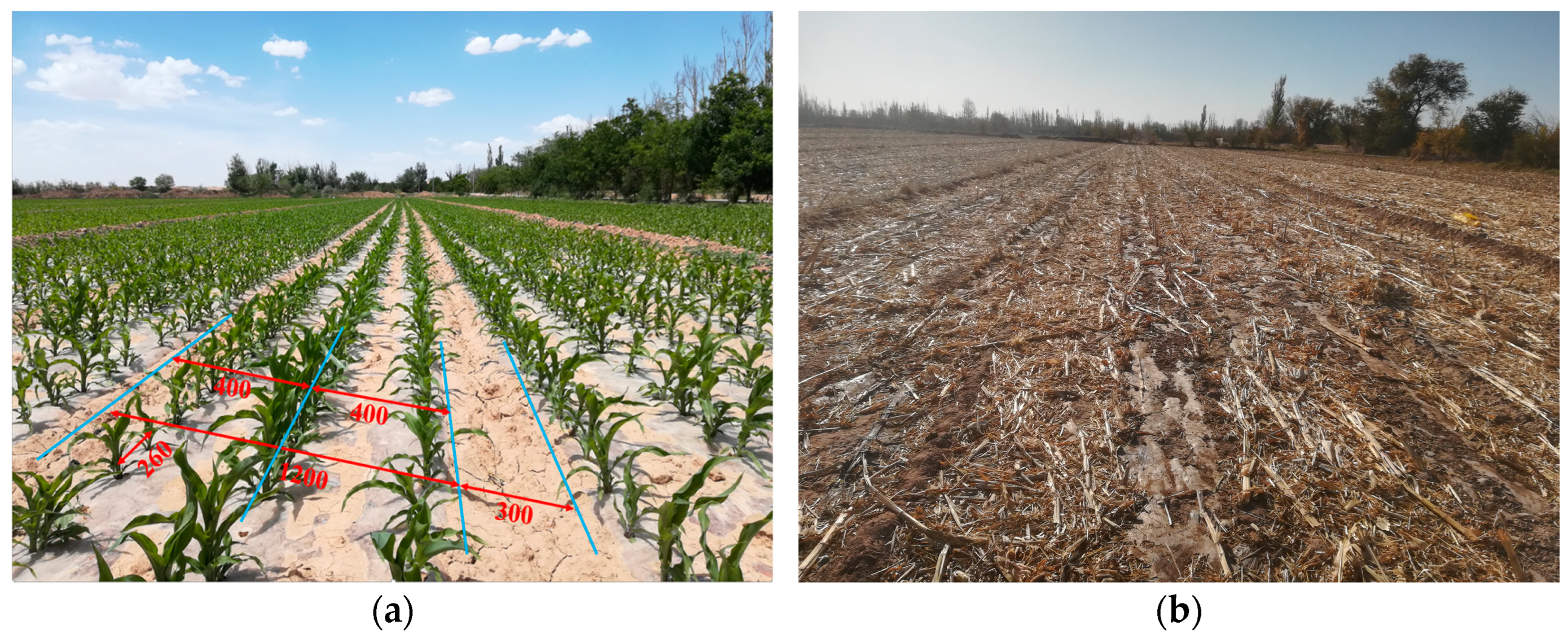
2.1. Corn Semi-Film Flat Planting Agronomic Model and Residual Film Recovery Conditions

The yield-increasing effects of different plastic film mulching planting methods for corn vary. The semi-mulching flat planting method demonstrates superior performance in terms of moisture conservation, ventilation conditions, and reduced pest and disease incidence, promoting early and complete seedling emergence. This method exhibits remarkable yield enhancement, with an average yield of 18,219.0 kg/ha. As an efficient water-, fertilizer-, and pesticide-saving cultivation model, it has been widely adopted and promoted in the Hexi irrigation region [36]. As shown in Figure 1a, the semi-film flat planting agronomic technique uses a plastic film with a width of 1400 mm for covering. After covering, the film belt width is 1200 mm, with a covering interval of 300 mm, row spacing of 400 mm, plant spacing of 260 mm, a plastic film thickness of 0.01 mm, and soil thickness covering the film of 10 to 15 mm. After the mechanized harvesting of corn, based on actual field measurements and statistics, it is known that the average height of corn straw is 600 mm, with many corn straws lodged and the ground surface covered with a large amount of corn straws and leaves. The average diameter of corn straw is 35 mm, and the average diameter of the stubble is 125 mm. Subsequently, farmers use corn straw pickup balers to mechanically bale the straw for use as dry feed for livestock. As shown in Figure 1b, after straw baling, the average height of the corn straw is 150 mm, and there are many corn straws and leaves on the surface of the plastic film. The soil is solid, the film surface is damaged, and the conditions for residual film recovery operations are quite complex.

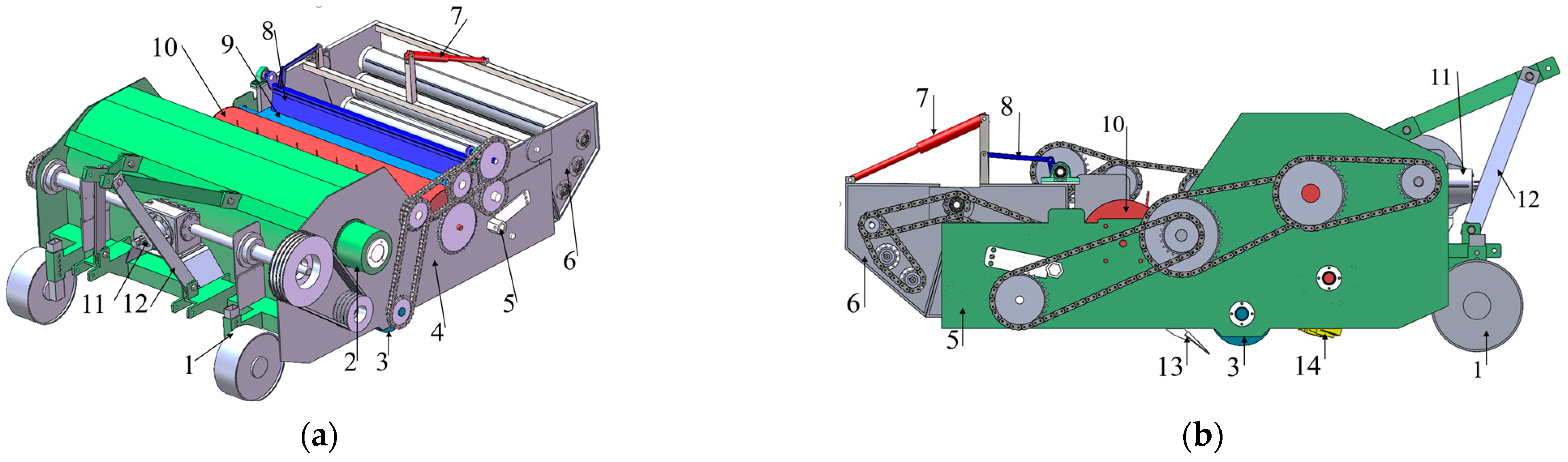
2.2. Overall Structure and Main Parameters

As shown in Figure 2, the combined operation machine consists of a suspension frame, straw-crushing device, lateral screw conveying device, film-lifting device, film-picking device, auxiliary film-shifting device, and film-collecting device. The corn straw-crushing and returning device crushes corn straw and returns it through a spiral arrangement of knives and an upper spiral conveyor, thereby shortening the longitudinal length of the machine for easier lifting. The film-lifting device is characterized by a double-wing, single-blade shovel with an adjustable angle. The film-picking device uses an eccentric teeth shifting cylinder, while the auxiliary film-shifting device uses a crank–rocker mechanism connected to a connecting rod, which enables it to complete the film-shifting process according to the expected motion trajectory. The film-collecting device consists of seven rotating rollers of equal diameters. The main parameters are listed in Table 2.

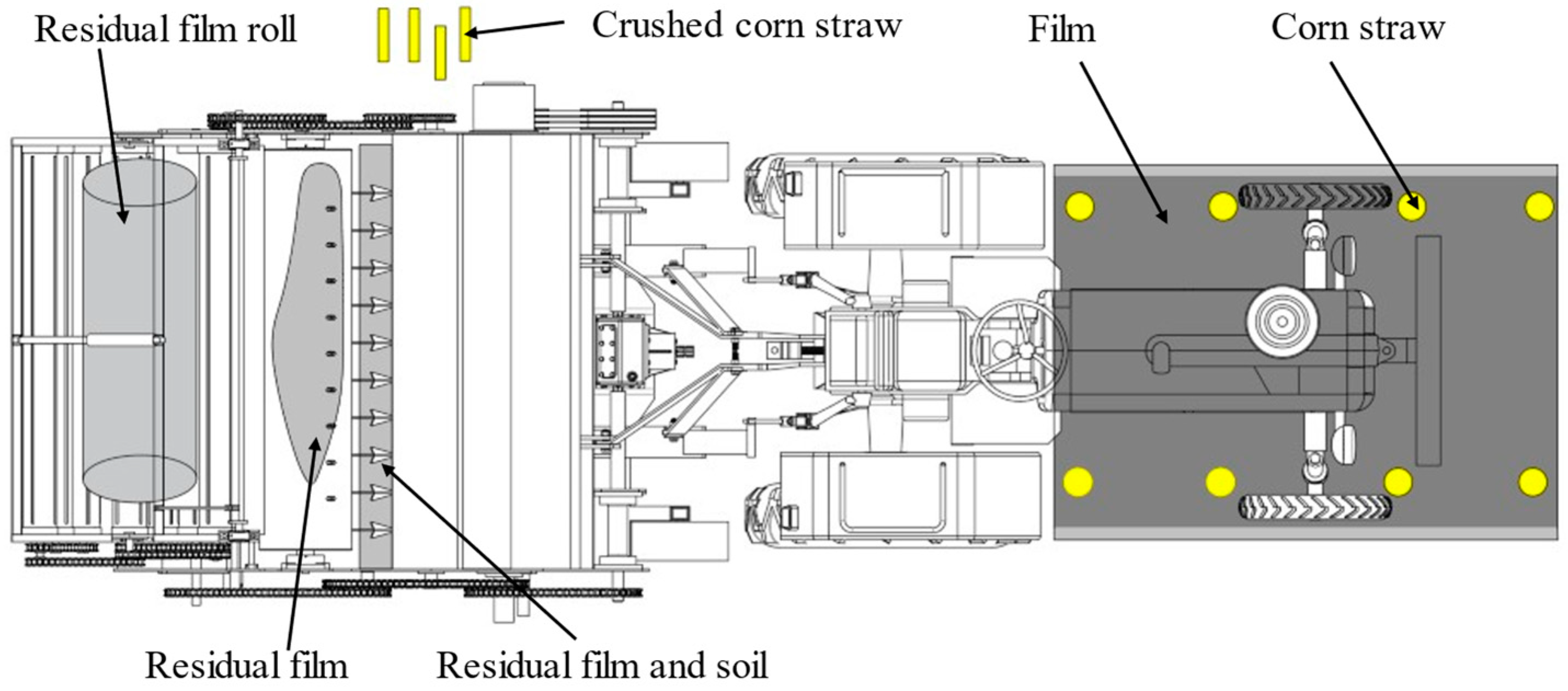
2.3. The Working Principle

As shown in Figure 3, when in operation, the tractor is connected to the transmission system of the whole machine through the rear power output shaft to drive the corn straw-crushing and returning device, as well as the film-collecting device. Meanwhile, the compression roller drives the eccentric teeth shifting cylinder to pick up the film, while the film-shifting mechanism is also activated. The corn straw-crushing device cuts the corn straw, stems, and leaves on the film surface using high-speed rotating flail knives. The crushed straw is fed into the screw conveyor, which laterally transports it to the area where the work has been completed, completing the tasks of corn straw crushing, returning, and film surface cleaning. Simultaneously, the suppression roller crushes the compacted soil and roots on the film surface. The film-lifting shovel lifts the residual film and cuts the corn stubble; then the residual film continuously accumulates, which is picked up by the eccentric telescopic rod tooth. The rod teeth retreat into the cylinder, and the film falls into the film-collecting box, assisted by the film-shifting device, where it rotates and forms a bundle. A small amount of the soil and corn straw carried with the film falls through the gaps of the rotating rollers, finishing the process of film bundling and separation of impurities. The hydraulic cylinder opens the movable part of the film-collecting box for film unloading when the film bundle reaches a specific volume.

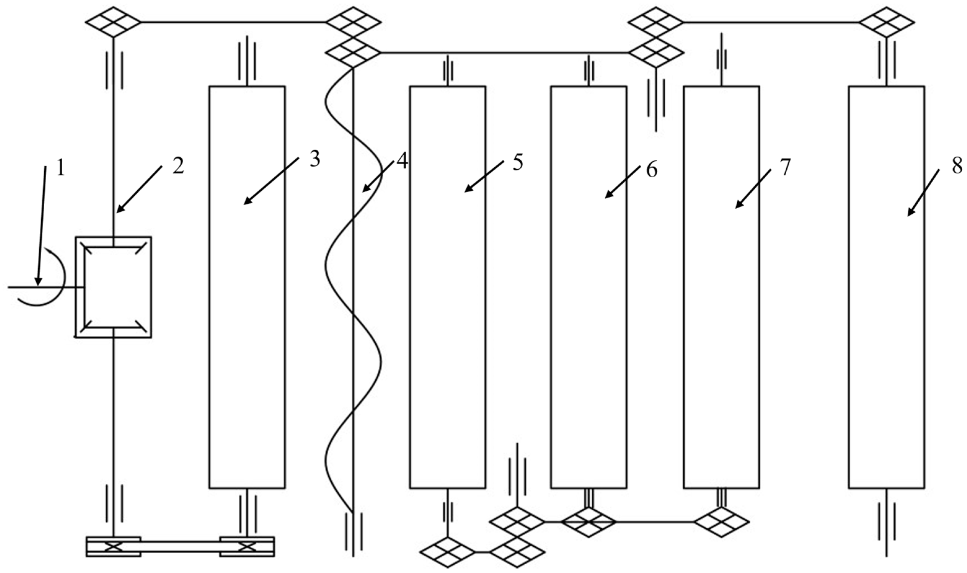
2.4. The Transmission System

The transmission system of the combined operation machine consists of two parts. The rear output power shaft of the tractor is connected to the gearbox of the combined operation machine through universal coupling, and the power of the gear box is transmitted to the straw-crushing and returning device and the film-collecting device through a belt drive and chain drive; the suppression roller transmits power to the eccentric teeth shifting cylinder and the auxiliary film-shifting mechanism with the chain drive to match their speeds. This transmission system features a compact structure, low power consumption, high transmission efficiency, and rational power distribution, and meets the speed requirements for both the corn straw-crushing and returning device and the residual film recovery device. Figure 4 shows the transmission line.

3. Key Mechanical Structure Design and Parameterization

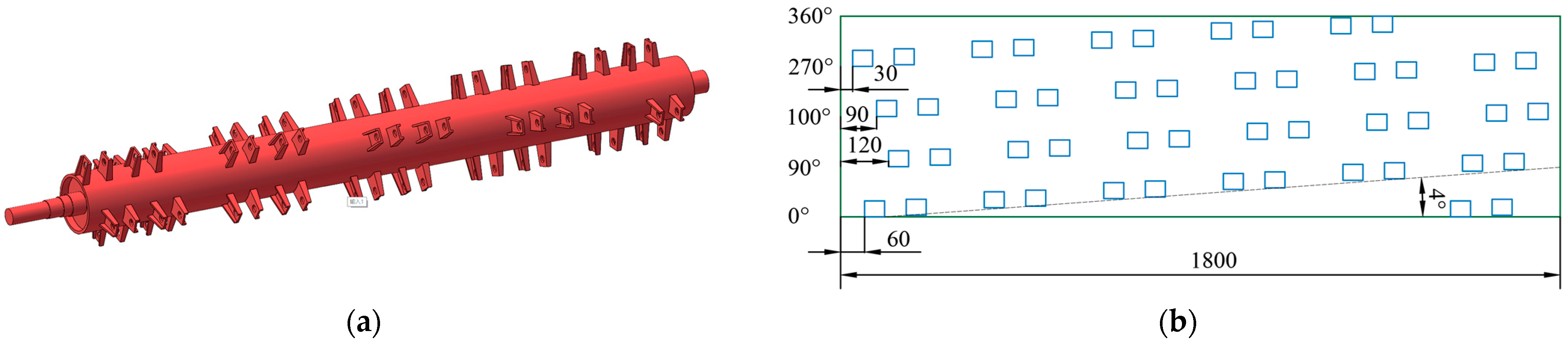
3.1. Corn Straw-Crushing and Returning Device

As shown in Figure 5, the corn straw-crushing and returning device consists of ground wheels, a knife shaft, moving blades, fixed blades, a casing, and a screw conveyor. During machine operation, the blade rotates at a high speed along with the shaft, causing serious power consumption and reducing the service life of the machine. Therefore, it is necessary to choose an appropriate blade shape, quantity, and arrangement.
Y-type moving blades should be selected, which are characterized by a small volume, low mass, and low resistance. These blades should be helically arranged and hinged on the knife shaft.
Based on the Agricultural Machinery Design Manual, the density of the Y-type moving blades in corn straw-crushing and returning devices is generally 0.23 to 0.4 pieces/cm. The calculation formula for the number of blades is
C = N / L
where N is the number of blades and L is the operational width (mm).
The density of the blade was selected as 0.27, the operational width was 1800 mm, resulting in 48 blades. The arrangement of blades affects the dynamic balance.
To determine the rationality of blade arrangement based on the Agricultural Machinery Design Manual, the verification equation is
I x x = ( n 1 ) × sin α 1 + ( n 2 ) × sin α 2 + sin α n 1 = 0 I y x = ( n 1 ) × cos α 1 + ( n 2 ) × cos α 2 + cos α n 1 = 0
where n is the number of blades and α is the arrangement angle of the knife seat (°).
The radial angle between two adjacent blades in the circumferential direction is 90°, and the knife shaft diameter is 160 mm. Based on Figure 5b, the data should be substituted into Equation (2), satisfying the equation and achieving a dynamic balance.
The angle of the arrangement of the blade seat affects operating performance. When the arrangement angle of the knife seat is less than 15°, the straw material in the crushing chamber form a laminar flow movement, the straw material retention time is extended, the material crushing pass rate and the degree of film surface cleanliness are better, and the residual film contains a lower rate of impurities. When the arrangement angle of the knife seat is around 45°, the straw material in the crushing chamber produces a vortex, and the centrifugal separation efficiency is improved, but causes a greater power loss. When the angle of the knife arrangement is greater than 60°, the speed of straw material along the crushing knife axis increases, but the separation time is shortened, the qualified rate of straw crushing and the degree of film surface cleanliness decrease, and the residual film contains a high rate of impurities. Based on the results of the field experiment, the arrangement angle of the knife seat should be set to 4°.
The absolute velocity at the tip of the moving knife is the resultant velocity of the machine’s forward speed and the linear velocity. The axis of the knife roller is the origin, and the negative X-axis is the forward direction. A Cartesian coordinate system is established, as shown in Figure 6. The equation of the trajectory of the point M (x, y) at the end of the moving blade is
x = v 0 ω 0 arcsin y R R 2 y 2
where v0 is the forward speed of the machine (m/s); ω0 is the angular velocity of the knife shaft (rad/s); and R is the rotating radius of the moving knife (mm).
The rotary tiller speed ratio is λ, which is the ratio of the linear velocity at the tip of the moving knife to the forward speed of the machine, expressed as
λ = V v 0
These can be derived from Equations (3) and (4).
x = R λ arcsin y R R 2 y 2
From Equation (5), the knife’s trace is a cycloid line. When the operating speed of the machine is less than the linear velocity at the tip of the moving knife, the curtate cycloid trajectory of the moving knife overlaps, and the corn straw-crushing quality meets the requirements [37]. When the moving knife reaches the highest point, the horizontal component of the linear velocity at the tip of the moving knife is completely opposite to the direction of the machine’s operating speed, facilitating the falling of the crushed corn straw into the spiral conveyor. The equation is expressed as
n = 30 V + v 0 π R
where n is the rotational speed of the knife shaft (r/min); R is the radius of the moving blade (m); V is the linear speed of the end of the moving knife (m/s); v0 is the forward speed of the machine (m/s).
The rotational radius R of the moving blade is 256 mm. Based on field test results, the rotational speed n of the knife shaft should be set at 2100 r/min, the forward speed v0 at 3~5 km/h, and the linear speed V of the knife tip’s linear velocity at 54.89~55.44 m/s, satisfying the minimum speed Vmin = 48 m/s for unsupported straw cutting.
Through the above analysis and calculation, the stability and reliability of the machine’s operation have been ensured, and unnecessary power consumption has been reduced.
Conveying efficiency is influenced by the structure and operating parameters of the screw conveyor. According to the design methods of screw conveyors [38,39], considering the high moisture content of corn straw after the autumn harvest in the Hexi irrigation area, a belt type spiral blade with a positive spiral surface should be selected. The advantage of belt-type spiral blades is that they can eliminate adhesion and accumulation during material transportation and are commonly used for conveying materials that are sticky or prone to clumping.
The screw conveyor, which is a critical component of straw-crushing and returning mechanical devices, and its parameter design directly affect the conveying efficiency, energy consumption, clogging rate, and equipment life.
The conveying angle of the spiral conveyor is 0°, which means it is placed horizontally to increase conveying efficiency and minimize energy consumption.
The diameter of the screw conveyor affects its conveying capacity. If the diameter is too large, it will lead to an increase in volume and power consumption. If the diameter is too small and the conveying capacity is weak, it will cause blockages. The diameter of the screw conveyor can be calculated using the following equation [37]:
D K Q ϕ ε ρ 2.5
where D is the diameter of the screw conveyor (m); K is the crushed straw characteristic factor; Q is the theoretical conveying capacity (kg/s); ϕ is the filling factor; ε is the tilt factor; and ρ is the packing density (t/m3).
Based on the Transportation Machinery Design and Selection Manual, the value of ϕ is 0.2, the value of K is 0.0071, the value of ε is 1, the value of Q is 0.3 kg/s, and the value of ρ is 0.12 t/m3. According to the calculation, the value of D is 196 mm, and the actual value of a is 200 mm.
If the pitch is too large, it will lead to increases in the conveying capacity per unit time but decreases in the contact area between the material and the blade, which may lead to slipping and reduce the conveying stability. If the pitch is too small, it will lead to the material filling rate increasing and the conveying becoming more uniform, but the conveying speed will decrease, and the power consumption will increase. The pitch of the screw conveyor can be calculated using the following equation:
S = ( 0.25 ~ 0.35 ) D
where S is the value of the pitch (m).
The formula for calculating the screw conveyor shaft diameter is
d = ( 0.5 ~ 2.2 ) D
where d is the value of the screw conveyor shaft diameter (m).
Taking a medium pitch, the actual value of S is 0.2 m, and the actual value of d is 0.1 m, thus balancing the conveying speed and stability and reducing the possibility of blockages.
If the spiral angle is large, the conveying speed will be fast, but the energy consumption will be high. If the spiral angle is small, it can convey stability but is more prone to clogging. The spiral angle of the screw conveyor can be calculated using the following equation:
α = arctan s π D
where α is the value of the spiral angle (°).
After substituting the numerical values into the equation, the value of α is 50°.
To sum up, the screw conveyor shaft diameter should be 100 mm, the screw blade diameter should be 200 mm, the screw angle should be 50°, and the screw pitch should be 200 mm. Figure 7 shows the structure.

3.2. Residual Film Recycling Device

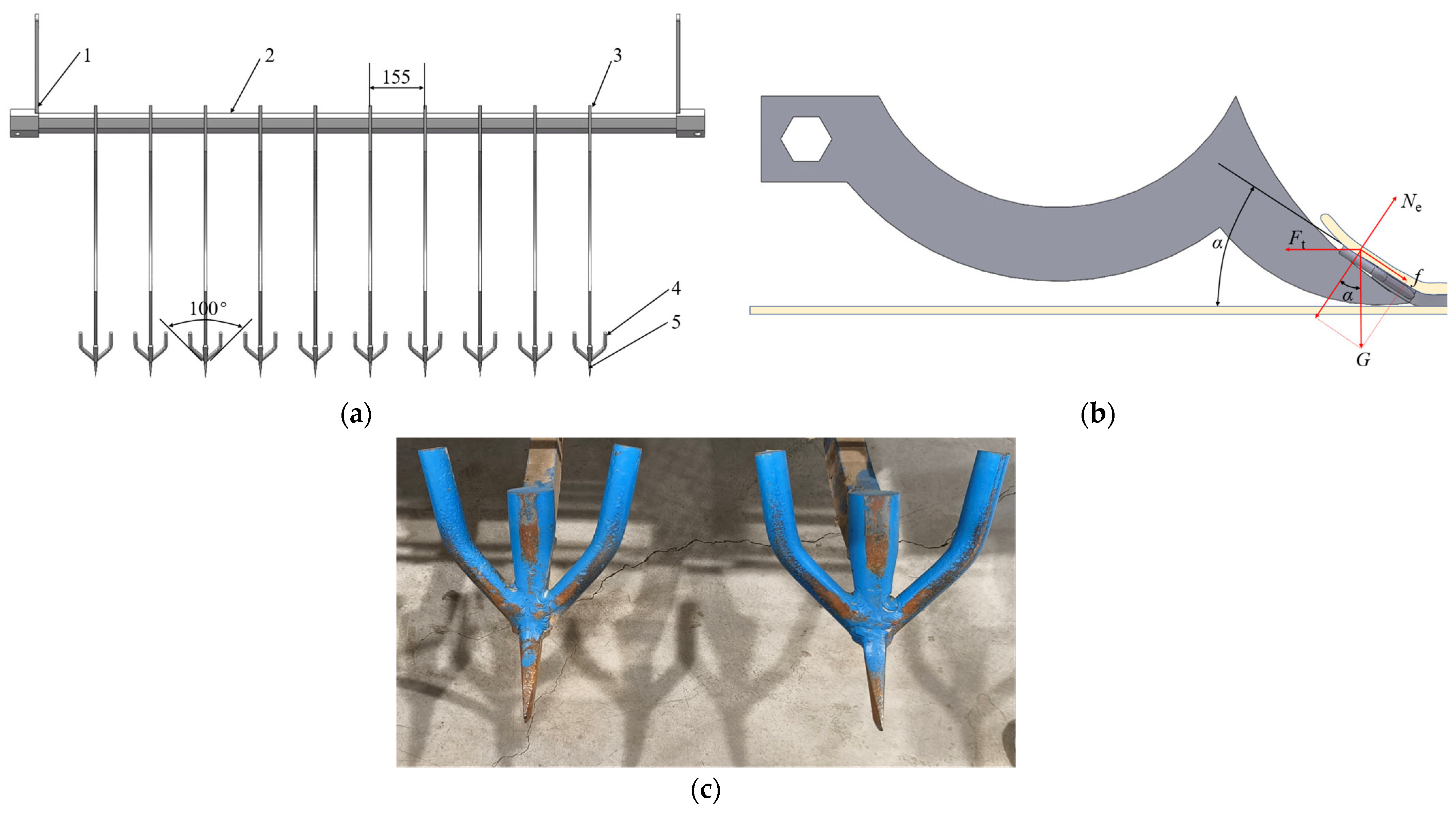
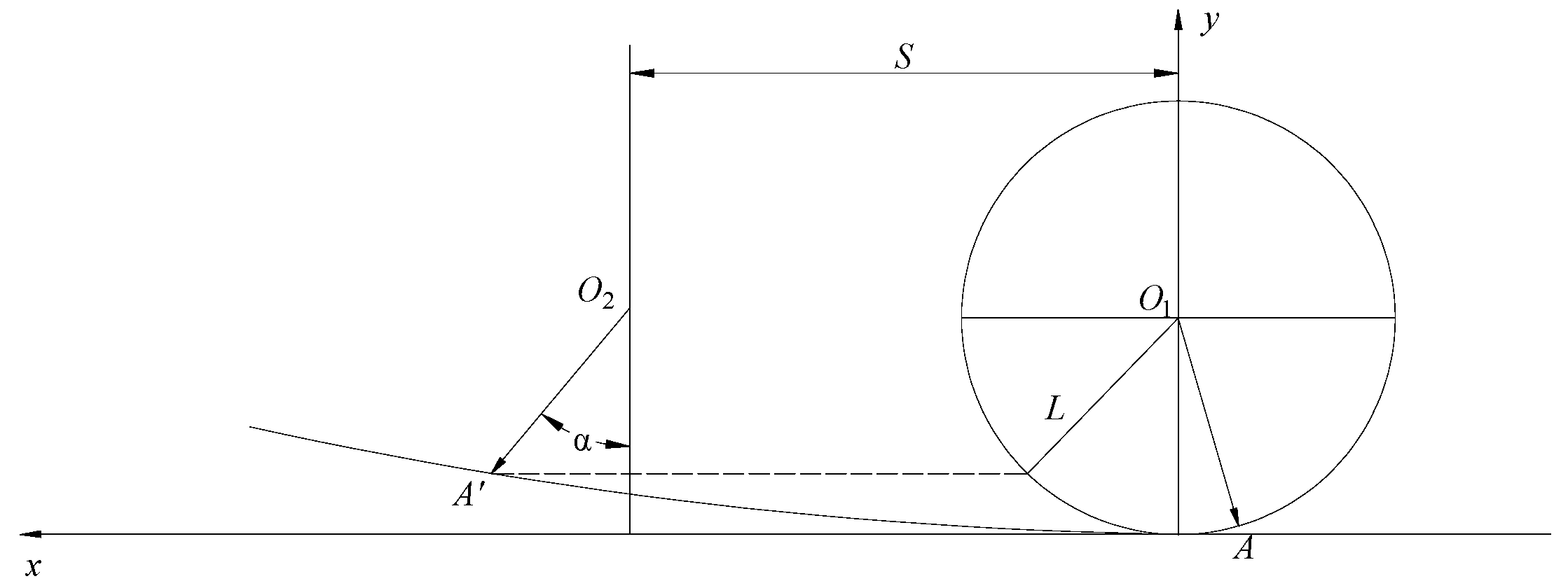
3.2.1. Film-Lifting Device

The film-lifting device is installed at the rear of the corn straw-crushing and returning device, comprising a film-lifting shovel single body, film-lifting frame, angle-adjusting mechanism, etc., and its structure is shown in Figure 8. The film-lifting shovel unit is made from an 8 mm steel sheet, with a main single blade and a U-shaped double wing welded to its front end. The main single blade is wide at the top and narrow at the bottom. The film-lifting shovel unit is fixed to the film-lifting frame, which is hinged to the machine frame, allowing the penetration angle of the film-lifting shovel to be adjusted between 20° and 30°. During operation, the film-lifting shovel enters the soil beneath the film, with its double wing completing the tasks of soil crushing and film lifting, while the main blade accomplishes the stubble-cutting task. The arrangement of the film-lifting shovel greatly affects the film-lifting effect. If the spacing between units is too wide, the film-lifting shovel cannot support the residual film, causing tearing of the film due to the weight of the soil under the film surface. Additionally, film tearing is difficult to pick up by the film-picking device because it is not lifted up by the film-lifting shovel, which reduces the recovery rate of the residual film and increases the film–soil separation difficulty. At the same time, the forward resistance of the machine and the power consumption are reduced. Conversely, if the spacing is too narrow, it causes clogging with impurities, enabling the film to mix with large masses of soil and be picked up by the picking up device, which creates a large amount of film pieces. This situation also reduces the residual recovery rate and increases the difficulty of film–soil separation. At the same time, the forward resistance of the machine and the power consumption increase. Based on the semi-film flat planting mode for corn and actual field operation conditions, the spacing between film-lifting shovel units should be 155 mm, and the angle between the double wings of the film-lifting shovel should be 100°.
Soil type, plunge depth, film-lifting shovel form, and film-lifting shovel penetration angle have a significant effect on shovel resistance, and the following relationship can be established:
F t cos α f G sin α = 0 N e G cos α F t sin α = 0
where f is the friction resistance of the film-lifting shovel (N); G is the soil gravity on the film-lifting shovel (N); Ne is the reaction force of the film-lifting shovel on the soil (N); α is the film-lifting shovel penetration angle (°); and Ft is the force required by the film-lifting shovel to lift the material along the forward direction (N).
ε = t a n φ
where ε is the friction coefficient of the contaminants on the film-lifting shovel, and φ is the angle of friction (°). Based on Equations (11) and (12), the film-lifting shovel penetration angle is as follows:
α = arctan F t ε G ε F t + G
To allow the residual film to accumulate on the film-lifting shovel and move forward along its surface, a parabolic guide surface was designed into the film-lifting shovel body. Its contour curve is shown as the curve AB in Figure 9, with the residual film represented by the gray area.
The tip of the film-lifting shovel is taken as the coordinate origin to establish the plane rectangular coordinate system oxy. The equation is as follows:
L 6 = L 5 s cos α h 1 = h s sin α
As can be seen from Figure 9, the coordinates of point A are (s cosα, s sinα), the coordinates of point B are (L5, h), and the equation of the parabolic guide curve of the film-lifting shovel is
x 2 + 2 m tan β n m + n tan α x y + ( m tan β n ) 2 ( m + n tan α ) 2 y 2 2 n tan α L 6 ( m + n tan α ) + h 1 ( m tan β n ) ( m + n tan α ) 2 x + 2 n L 6 ( m + n tan α + h 1 ( m tan β n ) ( m + n tan α ) 2 y = 0
where m = L6tanαh1; n = h1tanβ + L6; h1 is the height of the parabolic guide curve (mm); L6 is the opening degree of the parabolic guide curve (mm); h is the vertical distance of the film-starting shovel (mm); L5 is the horizontal distance of the film starting shovel (mm); α is the film-lifting shovel insertion angle (°); β is the angle between the tangent line at point B of the parabolic curve and the vertical direction (°); s is the length of the main edge of the curved teeth of the film-lifting shovel (mm).
From Equation (15), it can be seen that the shape of the parabolic guide curve is related to h1, L6, α, and β. Depending on the space structure of the machine design and the actual operation, h1 = 200 mm, L6 = 150 mm, and β = 5°. Additionally, the film-lifting shovel penetration angle α is a key parameter affecting the film-lifting performance and the recovery rate of the residual film. α was designed to be 20° to 30°, as determined through a field test.

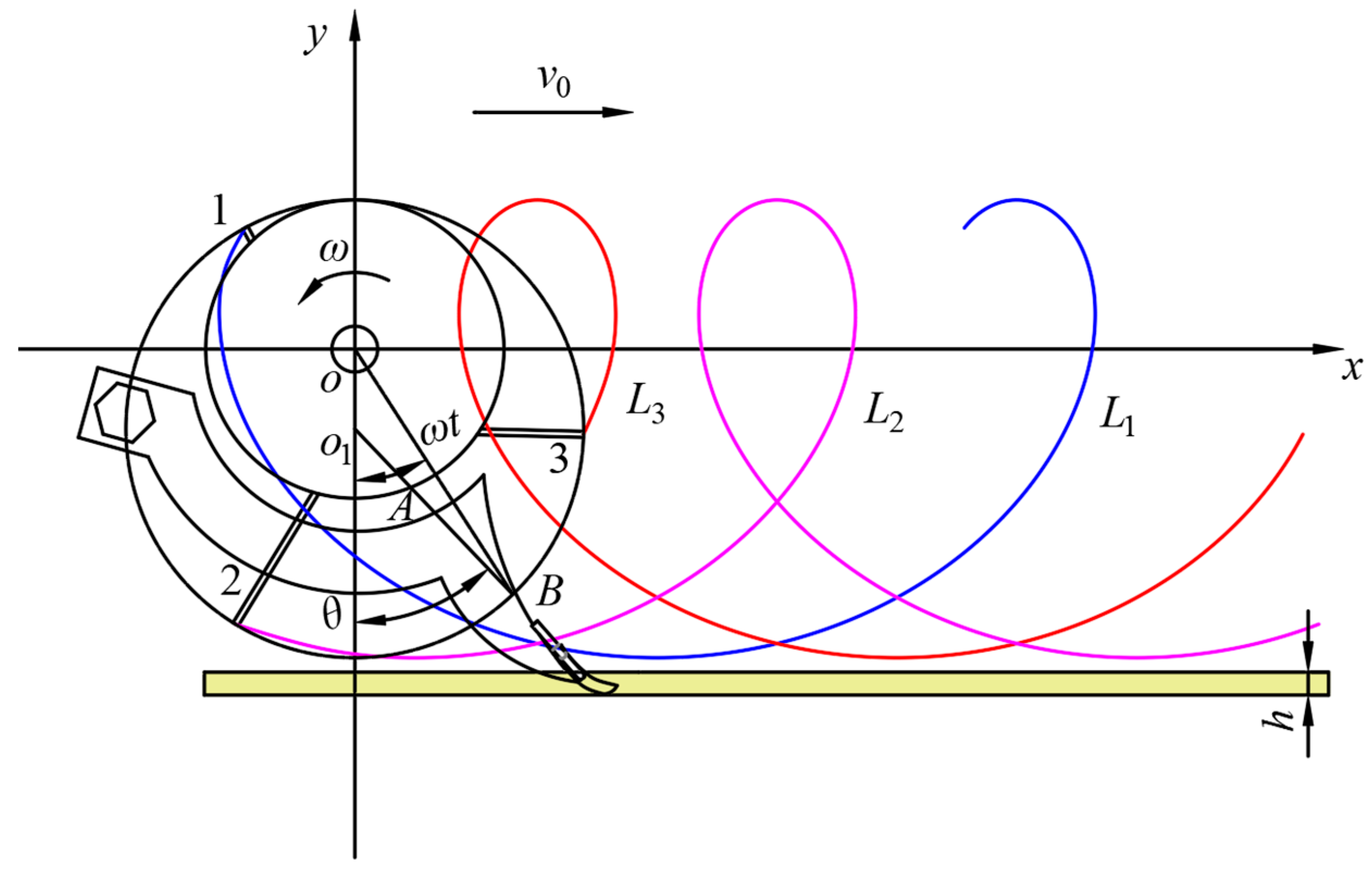
3.2.2. Film-Picking Device

As shown in Figure 10, the film-lifting device uses an eccentric telescopic rod tooth cylinder to take the residual film and send it to the film-shifting device. The film-picking device mainly consists of a film-picking cylinder, telescopic rod teeth, an end cover, and other components. The end cover is connected to the film-picking cylinder through bolts. The driving shaft is hollow, with an outside diameter of 70 mm and an inside diameter of 42 mm. It is welded to the end cover, while the eccentric shaft is fixed to the frame and constitutes a shaft-in-axis structure with the driving shaft. The telescopic rod teeth are connected to the eccentric shaft through the rotary joint to lengthen and shorten along the long holes on the wall of the cylinder. The sprocket wheel is connected to the driving shaft through the key; the diameter of the drum is 380 mm, and there are three rows of telescopic rod teeth distributed uniformly in the circumferential direction. The telescopic rod teeth shafts are connected to the driving shaft by keys.
The axial distance is 155 mm between the three rows of telescopic rod teeth, uniformly distributed in the circumferential direction. In operation, the motion of the telescopic rod teeth is a combination of forward and rotational motion. The motion trajectories of the telescopic rod teeth 1, 2, and 3 in the circumferential direction are L1, L2, and L3, which are shaped as cycloids, as shown in Figure 11. The machine’s forward direction is the direction of the X-axis, with point o of the eccentric drum rotation axis as the origin. The Y direction extends vertically upward, the radius of the drum is R, the length of the telescopic rod teeth o1AB is L, the length of the crank oo1 is E, which is the length from the cylinder rotary center to the telescopic rod teeth rotary center, and the cylinder’s angular velocity is ω. After a period of time t, the telescopic rod teeth transition from the vertical position to the position of the o1AB, the intersection point of the telescopic rod teeth and the cylinder is A, and the angle of the cylinder is ωt. The equations of motion at points A and B are as follows:
x A = v 0 t R sin ω t y A = R cos ω t
x B = v 0 t L sin θ y B = L cos θ
where θ is the angular displacement of the teeth of the eccentric telescopic rod after time t has elapsed (°); v0 is the forward speed of the machine (m/s); R is the radius of the cylinder (mm); L is the length of the telescopic rod teeth (mm); and ω is the cylinder’s angular velocity.
Figure 11 traces the movement of the telescopic rod teeth, where the blue line is the trace of the telescopic rod teeth 1, the purple line is the trace of the telescopic rod teeth 2, the red line is the trace of the telescopic rod teeth 3, and the yellow area represents the soil layer.
Analyzing the geometric relationships in Figure 11 leads to the following equation:
θ = arcsin sin ω t 1 + ε 2 2 ε cos ω t
where θ = E/R; E is the length of the crank (mm); and R is the radius of the drum (mm).
Derived from the above Equation (17), the equation for the velocity of motion of the telescopic rod tooth endpoint B at any position is
v B x = v 0 L cos θ v B y = L sin θ
When the telescopic rod teeth rotate directly above the cylinder, the residual film is removed smoothly. vBx ≤ 0 can be obtained from Equation (19).
v 0 L sin θ
The ratio of the linear velocity vB at the endpoint of the telescopic rod teeth to the forward velocity v0 of the machine is defined as λ. The equation is as follows:
λ = v B v 0
where λ reflects the degree of matching between the velocity of the film-picking device and the forward speed of the machine. If λ is large, it means that the film-picking device will pick up more film at once, which will result in a large amount of broken film. If the value of λ is small, it means that the speed of the film-picking device will slow, and it will struggle to pick up the film. Both situations result in lower residual film recovery rates; thus, λ has to take a suitable value. In general, when λ varies between 1.2 and 1.6, the film-picking effect is better. Under these circumstances, during operation, the film pick-up teeth extend so that the lifted residual film cannot fall off.
As shown in Figure 12, when λ > 1, the path forms a long pendulum line, resulting in an increased extended length at the film-lifting shovel. The overlapping film-picking area between two neighboring telescopic rod teeth also increases, ensuring continuous film picking. By substituting R = 190 mm, E = 104 mm, L = 300 mm, and v0 = 4 km/h into the above equation, the drum speed was initially determined to be 70~90 r/min.
The operational performance is related to the number of rows of teeth of the telescopic rod. If the number of rows is too small, the film may not be picked up effectively. In contrast, a large number of rows increases the power consumption and may cause the film to tear more easily.
As shown in Figure 12, the machine advances from point o1 to point o2, and forward S. The telescopic rod teeth move from point A to point A′, and the telescopic rod teeth rotate at the angle α relative to the film-lifting device. The calculation formula for the number of rows is [37]
z = 30 v 0 L n sin α
where S is the forward distance (m); v0 is the forward velocity (m/s); L is the length of the telescopic rod teeth (m); n is the rotational speed of the film-picking device (r/min); and α is the angle of rotation of the film-picking device (°).
Substituting known data, the calculation of Equation (22) results in 3. Therefore, the number of rows of teeth of the telescopic rod is 3.

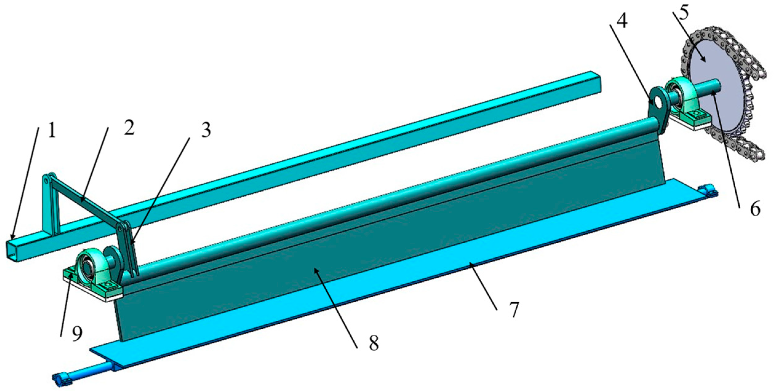
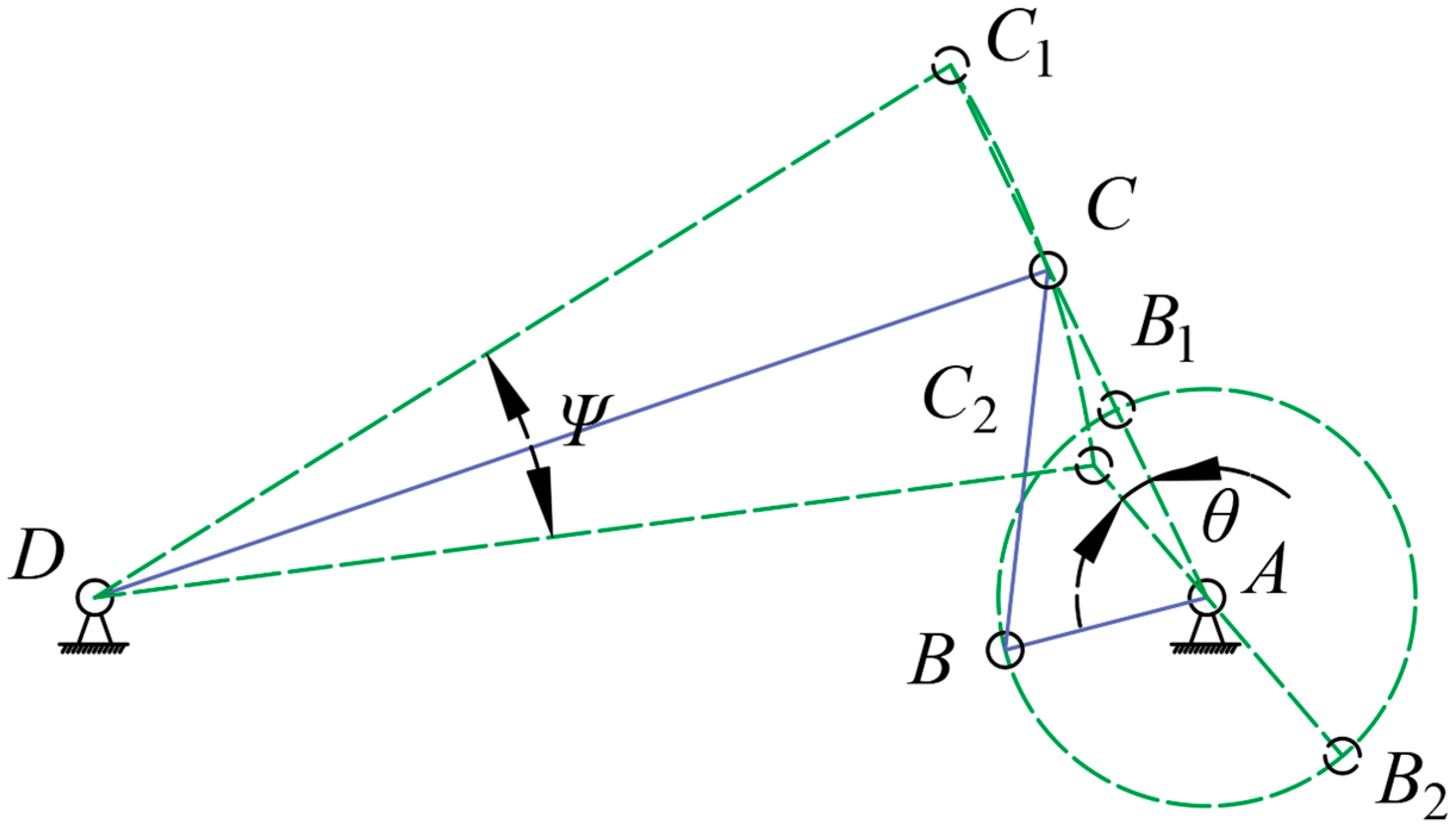
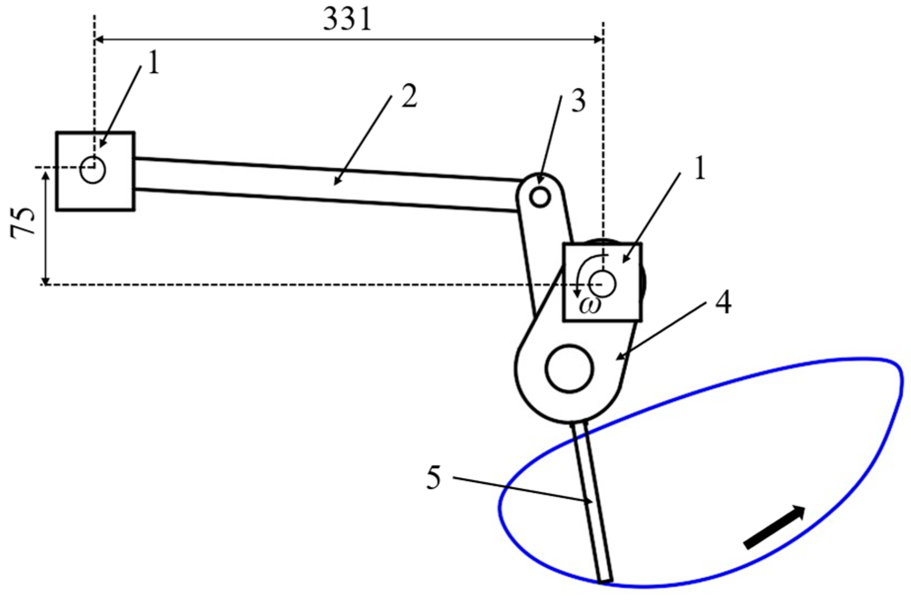
3.2.3. Film-Shifting Device

Compared to other mechanisms, the crank rocker has lower structural complexity, lower maintenance costs, and significant quick return characteristics. The use of rapid return characteristics can improve the efficiency of the film-shifting device by reducing idle time, utilizing inertia reasonably, and reducing energy loss.
The film-shifting device seeds the residual film from the telescopic rod teeth to the film-collecting box as shown in Figure 13. Therefore, the film-shifting device adopts the crank–rocker mechanism, which is mainly composed of the frame, crank, connecting rod, rocker, crank shaft, film-shifting plate, and film-guiding plate.
The geometric dimensions of each component of the crank–rocker mechanism affect the motion trajectory of the shifting plate, thus affecting the shift film effect. To determine its structural dimensions, its structure should be simplified, as shown in Figure 14. The crank’s rotary center is recorded as hinge point A, the point of connection between the connecting rod and the crank is recorded as point B, the connecting rod and the rocker connection point is recorded as point C, and the connecting rod’s oscillation center is recorded as hinge point D. The lengths of the crank AB, the connecting rod BC, the rocker CD, and the rack AD are, respectively, LAB, LBC, LCD, and LAD.
The crank–rocker mechanism has a significant quick return characteristic, and the equation of the crank angle between two limit positions is
θ = 180 ° K 1 K + 1
where K is the travel speed ratio coefficient of the crank–rocker mechanism.
From the geometrical relationship of the crank–rocker mechanism at the two limit positions in Figure 14, the following equation can be obtained.
L C 1 C 2 = 2 L C 1 D sin ψ 2 L C 1 C 2 2 = L B 2 C 2 L A B 2 2 + ( L A B 1 + L B 1 C 1 ) 2 2 L B 2 C 2 L A B 2 ( L A B 1 + L B 1 C 1 ) cos θ
Reorganizing Equation (24),
L A B 2 2 cos 2 θ 2 + L B 2 C 2 2 sin 2 θ 2 = L D B 2 2 sin 2 ψ 2
where ψ is the oscillation angle of the rocker (°).
In general machines, the travel speed ratio coefficient K ranges from 1 to 2. The larger the value of K, the more obvious the quick return characteristic of the crank–rocker mechanism. The film-shifting device needs to quickly realize the separation and transmission of the accumulated residual film at the film guide plate. The film-shifting mechanism performs a sharp return movement, which requires a travel speed ratio coefficient K > 1. However, if K is too large, the movement becomes unstable. In this paper, the coefficient K was set to 1.2. Using Equation (23), the corresponding angle θ was calculated to be 15°. According to the installation position of the film-shifting mechanism and the actual operation effect, LCD = 290 mm, LAB = 60 mm, and ψ = 24°, and the above parameters were substituted into Equation (25) to obtain LBC = 110 mm.
As shown in Figure 15, based on motion simulation analysis of the film-shifting mechanism in SolidWorks2021 Motion, the blue line is the trace of motion of the end of the shifting plate. From the trajectory, it can be seen that during the working stroke, the shift plate smoothly pushes the residual film backward and upward so as to fall into the film-collecting device. During the return stroke, the trajectory of the shifting plate is approximately straight and moves rapidly, preventing the residual film from being taken back and accumulating at the film guide plate.

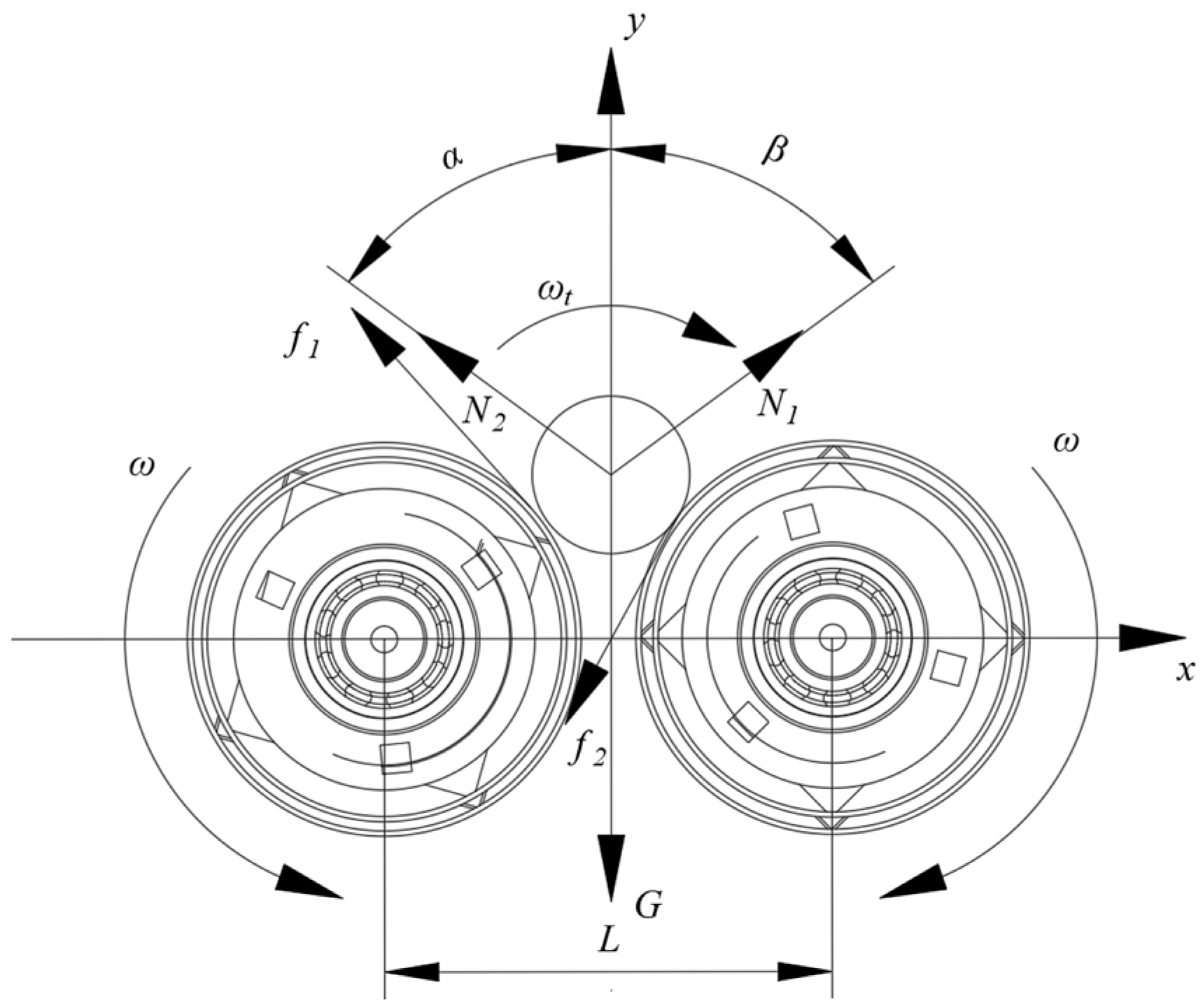
3.3. Film-Collecting Device

As presented in Figure 16, the residual film recycling device mainly consists of a fixed box, a movable box, a sprocket, film rollers, and hydraulic cylinders. There are seven film rollers, each designed as a round rotating roller. Four angle steels are installed axially on the outer surface of each roller to increase friction. When the film-collecting device is unloading the film, the hydraulic cylinder lifts up the moving box, and the residual film slides down from the film rollers of the fixed box.
Here, N1 is the support force of the left film roller on the residual film (N); N2 is the support force of the right film roller on the residual film (N); f1 is the friction force between the left film roller and the residual film (N); f2 is the friction force between the right film roller and the residual film (N); α is the angle between the support force of the right film roller and the vertical direction (°); β is the angle between the support force of the left film roller and the vertical direction (°); G is the gravity of the residual film (N); ω is the film roller angular velocity (rad/s), where the direction of movement as shown by the arrow; ωt is the rotational angular velocity of the residual film (rad/s), where the direction of motion is shown by the arrow; L is the distance from the center of the film rollers (m).
During the packing process, the packed residual film is assumed to be cylindrical in shape, and the forces on it are analyzed, as shown in Figure 17.
The static forces on the residual film are analyzed, and the horizontal and vertical forces can be expressed by the following equation:
f 1 cos β + N 2 sin α + f 2 cos α = N 1 sin β N 2 sin α + N 1 sin β + f 1 sin β = G + f 2 sin α f 1 = μ N 1 f 2 = μ N 2
where μ is the coefficient of friction between the film roll and the residual film.
The rotational torque experienced by the residual film can be expressed by the following equation:
M = ( f 1 + f 2 ) r
where r is the radius of the residual film roller (m).
The following equation can be obtained from the analysis:
M = G r ( sin α + 3 cos α μ cos β + sin β ) sin β ( 1 μ ) ( sin α + cos α μ cos β + sin β ) ( sin α + cos α )
By analyzing Equation (28), the greater the rotational torque of the residual film, the easier the residual film is packed at the bottom of the collection box. At this time, α and β are approximately equal, and the following equation can be obtained:
M = G r tan α ( 1 μ ) ( tan α + 1 )
By analyzing Equation (29), the rotational torque received by the residual film is related to α, μ, and r. When M is larger, it is easier for the residual film to form a film core in the roll. The volume of the residual film roller increases with running time, r is increased, α is decreased, the residual film roller’s center of gravity rises, and the rotating torque is increased. As a result, increasing friction by adding four angle steels to the film rollers is the best and simplest option to improve the film rolling efficiency.

4. Results

4.1. Experimental Conditions

In October 2024, a field experiment was conducted in Liangzhou District, Wuwei City, Gansu Province, China. The previous crop grown on the test site was corn, covering an area of 4 hm2. The test field consisted of irrigated desert soils, with a soil firmness of 385 kPa and a soil water content of 18.4%. The ground surface was covered with a large amount of corn straws, stems, and leaves. The mean height of the straws was 150 mm, their mean diameter was 35 mm, and their water content was 18.21%. The width of the film was 1400 mm, its thickness was 0.01 mm, and the thickness of the soil covering the film was 30~50 mm. The surface of the film was affected by ultraviolet radiation and mechanical operations, and the film surface was prone to longitudinal tears or holes, with some of the edge areas having been rolled and broken due to wind. The degree of aging of the experimental field film was characterized by surface brittleness, increased cracks, and decreased transparency, especially in the long-term film covering the area. The supporting power was an 88.3 KW tractor. The scenes and performance of the machine are shown in Figure 18.

4.2. Test Factors and Test Indicators

The residual film recovery rate is affected by many factors. In this study, a three-factor, three-level quadratic regression orthogonal test was carried out using Design-Expert 13 software, and the three key factors, namely, the angle of the film-lifting shovel X1, the speed of the eccentric telescopic rod and tooth cylinder X2, and the machine forward speed X3, were used as the key influencing factors to take the residual film recovery rate as the response value. Table 3 shows the range of values for the test coefficients.
The measurement methods for the residual film recovery rate, residual film impurity rate, and the qualified rate of corn straw crushing are as follows:
Before recycling, five experimental areas with a length of 20 m and a width of 1.4 m were randomly selected for data statistics, manual pick up was carried out to ensure that there was no missing film, and the residual film samples were cleaned and dried. When the machine had stabilized during the field experiments, five experimental areas with a length of 1 m and a width of 1.4 m were randomly selected for data statistics. After the current set of experiments, the plastic film was removed from the collection box, and we proceeded to the next set of experiments, for which the residual film samples were cleaned and dried. Finally, the weighing data were recorded, and the residual film recovery rate was determined according to GB/T25412-2021 (Farm waste film-pick up machines) [40]. The recovery rate of the residual film recycling machine is calculated as follows:
Y 1 = m 0 m 1 m 0 × 100 %
where Y1 is the residual film recovery rate (%); m0 is the mass of residual film manually picked up before the operation (g); and m1 is the missed quality of the residual film (g).
After machine operation, the contents of the film-collecting box were weighed, and the residual film samples were cleaned and dried, before the weighing data were recorded. The formula for calculating the impurity rate is
Y 2 = w 0 w 1 w 0 × 100 %
where Y2 is the impurity rate (%); w0 is the total mass of impurities in the film-collecting box (g); and w1 is the mass of residual film (g).
After recycling, five experimental areas of 5 m2 were randomly selected for data statistics. The weight of all straw in the measurement area was calculated, followed by the weight of the crushed corn straw considered qualified, where a corn straw length of ≤150 mm is defined as qualified. Under GB/T 24675.6-2021 (Conservation tillage equipment—Part 6: Smashed straw machine) [41], the formula for calculating the qualified rate of corn straw crushing is
Y 3 = u 1 u 0 × 100 %
where u0 is the weight of all straw in the measurement area (g), and u1 is the weight of qualified corn straw (g).

4.3. Test Results and Analysis

4.3.1. Test Results

The test consisted of 17 test points. Each test was repeated three times, and the average value was taken. A total of 51 tests were required, and the test results are shown in Table 4.

4.3.2. Experimental Regression Analysis

ANOVA is a statistical method used to study the effect of one or more categorical independent variables on a continuous dependent variable, and it is widely used, with the results summarized in a table called an ANOVA table [42].
SST is the difference between all observed values and the total mean, and its formula is
S S T = i = 1 N ( y i y ¯ )
where yi is the value of the i-th observation; y ¯ is the overall mean of all observations; and N is the total.
SSB, which represents the square difference between the mean of each group and the total mean, is calculated using the following formula:
S S B = k = 1 k n k ( y ¯ k y ¯ ) 2
where nk is the number of samples in group k, and y ¯ k is the average of group k.
SSE takes the difference between the observations within each group and their group means, and its formula is
S S E = k = 1 k i = 1 n k n k ( y k i y ¯ k ) 2
where yki is the i-th observation of the k-th group.
The average square is SSB and SSE divided by the corresponding degrees of freedom. The size of the F-value reflects the ratio of intergroup differences to intragroup differences. The formula is
M S B = S S B d f   b e t w e e n d f   b e t w e e n = k 1 M S E = S S E d f   w i t h i n d f   w i t h i n = N k
F = M S B M S E
The results of the significance test were calculated and are shown in Table 5. The model significance test was p < 0.0001, indicating that the test of the quadratic regression equation reached a high degree of significance. Therefore, the regression equation can be used to analyze the results of the test instead of the test of the real point. The test of the loss of fit, F = 1.9, p > 0.1, was not significant, so the model is a good fit.
The optimized regression equation can be obtained by removing the insignificant regression terms in the model.
Y = −259.975 + 4.275X1 + 5.395X2 + 38.725X3 + 0.005X1X2 − 0.0345X22 − 5.2X32

4.4. Analysis of the Influence of Interaction Factors on the Working Performance of the Machine

In this study, the Box–Behnken experimental design method was used. Compared to other methods, such as Taguchi and response surface methodology, Box–Behnken has a wide range of applications, requires fewer experiments, and is suitable for sampling the behavior of multi-parameter functions. Its structured yet flexible framework is ideal for optimizing complex processes in fields like chemistry, biotechnology, and environmental engineering. The effect of the test factors on residual film recovery is presented in Figure 19, where the darker the color of the response surface, the larger the value represented by the position. From Figure 19 and Table 5, the following order of significance of the test factors was obtained: Film-lifting shovel into the soil angle > the rotational speed of the eccentric teeth shifting cylinder > the machine operating speed, and interaction effects of the factors on the residual film recovery rate existed. From Figure 19a, when the machine operating speed was fixed at 4 km/h, the interaction between the film-lifting shovel into the soil angle and the rotational speed of the eccentric teeth shifting cylinder showed that as they increased, the rate of residual film recovery first increased and then decreased, which is due to the increase in the angle of film-lifting shovel into the soil and the decrease in the rate of missed residual films. The continued increase in the angle of the film-lifting shovel into the soil resulted in the stubble being shoveled up, leading to an increase in the clogging rate of the film. This is because the rate of missed residual films decreased when the angle of the film-lifting shovel into the soil increased. As can be seen from Figure 19b, when the eccentric teeth shifting cylinder rotation speed was 80 r/min, the angle of the film-lifting shovel into the soil and the machine operating speed interaction law showed that when they increased, the recovery rate of the residual film first increased and then reduced, and the forward direction of the magnitude of change increased. This is because of the increase in the operating speed of the machine, which makes it harder for stubble to be shoveled, thus weakening the phenomenon of clogging. As the operating speed increased, the rate of missed residual films increased; therefore, the angle of the film-lifting shovel into the soil and the operating speed of the machine should be controlled in a reasonable range. As shown in Figure 19c, when the angle of the film-lifting shovel into the soil was fixed at 25°, the interaction between the eccentric teeth shifting cylinder speed and the speed of machine operating showed that when they increased, the rate of residual film recovery increased and then decreased, and the rate of residual film recovery was the largest when the ratio of the rotation speed of the eccentric teeth shifting cylinder and the operating speed of the machine was 1.4.

4.5. Parameter Optimization and Experimental Validation

A polynomial objective function was established, and Design-Expert 13 software’s optimization function was used to optimize the operation parameters. The experimental factors were limited to the following: The angle of the film-lifting shovel into the soil ranged from 20° to 30°, the rotational speed of the eccentric teeth shifting cylinder was between 70 and 90 r/min, and the operating speed of the machine was 3 to 5 km/h. The evaluation index for the residual film recovery rate, η, aimed for a maximum target value of 100%. After optimization, the operation parameters for the equipment were a film-lifting shovel insertion angle of 25.14°, an eccentric teeth shifting cylinder rotational speed of 80.96 r/min, and a machine operating speed of 4.03 km/h, with a theoretical residual film recovery rate of 92.56%.
To test the precision of the optimization outcomes, the experiment was replicated five times in Liangzhou District, Wuwei City, Gansu Province, China. Based on previous field experiments, the depth of penetration of the film-lifting shovel was set to 80 mm, and the machine operating speed was set to 4 km/h, depending on the gearing of the tractor. The rotation speed of the eccentric teeth shifting cylinder was changed by changing the sprocket, which adjusted the transmission ratio. The rotation speed was set to 80 r/min, and the angle of the film-lifting shovel into the soil was set to 25°. Table 6 presents the results. According to the test results, the average residual film recovery rate of the equipment was 91.96%, and the ground surface was clean after film recovery. A small amount of residual film was not recovered because the corn straw’s aerial roots penetrated the residual film in an umbrella-like fashion, causing some residual film around the corn straws to be unrecovered.
According to the methods described in Section 4.2 and the five field experiments, the experimental results of the residual film impurity rate and the qualified rate of corn straw crushing are presented in Table 7.
The results from the field tests show that the operational performance indicators of the experimental prototype meet the requirements of field agriculture.

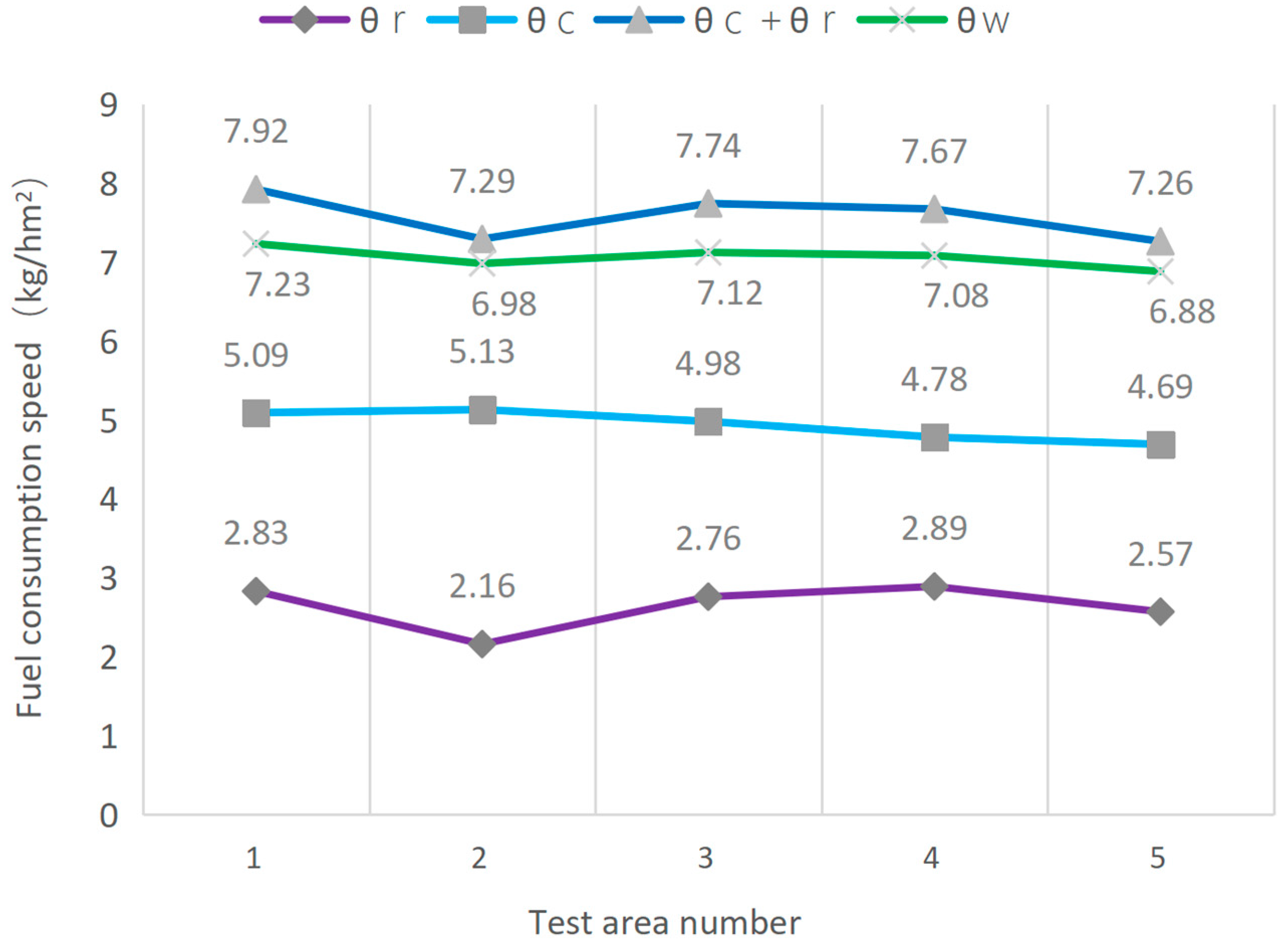
4.6. The Power Consumption Test

Based on GB/T 24643-2009 (Fuel consumption of tractor set during field operation—Test methods) [43], the fuel tank was filled up before the experiment, the operating area after the whole machine started working was recorded, and then the fuel tank was filled up again after the experiment had been completed. The weight of the added fuel was recorded, which reflects the weight of the consumed fuel. Power consumption was measured in terms of fuel consumption speed. The calculation formula is as follows:
θ T = G z S
where θT is the fuel consumption speed (kg/hm2); GZ is the fuel consumption per operation (kg); and S is the operating area (hm2).
Power consumption was divided into the power consumption of the corn straw-crushing and returning device and that of the residual film recycling device, and finally, the power consumption of the whole machine was tested. Power consumption was reflected in fuel consumption. The total area of the test plot was 3.6 hm2 and was divided into six groups on average. Each measurement was repeated five times.
First, the tractor’s rear output power was cut off, and then the angle of the film-lifting shovel was adjusted to avoid contact with the ground, before the machine was operated for 0.6 hm2. The fuel consumption speed θ0 was recorded. Power was only provided to the corn straw-crushing and returning device and tractor, and the angle of the film-lifting shovel was adjusted to avoid contact with the ground, before the machine was operated again for 0.6 hm2. The fuel consumption speed θ1 was then recorded. Next, power was only provided to the residual film recycling device and tractor, and the angle of the film-lifting shovel was adjusted to restore the original angle, before the machine was operated for another 6 hm2. The fuel consumption speed θ2 was then recorded. Finally, the whole machine was operated for 0.6 hm2, and the fuel consumption speed of the whole machine θw was recorded. The formulae for calculating the fuel consumption speed of the corn straw-crushing and returning device and the residual film recycling device are as follows:
θ c = θ 1 θ 0
where θc is the fuel consumption speed of the corn straw-crushing and returning device (kg/hm2).
θ r = θ 2 θ 0
where θr is the fuel consumption speed of the residual film recycling device (kg/hm2).
The test results are shown in Figure 20.
According to Figure 20, the power consumption of the whole machine was lower than the sum of the power consumed by the corn straw-crushing and returning device and the residual film recycling device. Therefore, the machine can not only simplify the work process but also reduce energy consumption and increase work efficiency.

4.7. The Component Durability Test

On this machine, the film-lifting shovel, Y-type moving blades, and telescopic rod teeth wear relatively easily. To track their wear, the machine worked continuously for 10 days, 7 h a day, measuring the wear and deformation five times. The average value was then taken, and the test results are shown in Figure 21.
After 10 days of testing, there was no damage or replacement of any components. The wear of the film-lifting shovel, Y-type moving blades, and telescopic rod teeth was minimal and did not affect normal operation. The film-lifting shovel needs to be in direct contact with the soil, so the amount of wear is the largest. To reduce wear and extend the machine’s life, 65 Mn steel, which is characterized by high strength and wear resistance, was used as the material. The Y-type moving blades, which come into direct contact with corn stubble, were also made of 65 Mn, enhancing their wear resistance and service life. Moreover, both the Y-type moving blades and the telescopic rod teeth used standardized fittings in China, making them easy to replace in case of damage. Since the telescopic rod teeth come into contact only with residual film and a small amount of soil and stones, wear is minimized. Therefore, the durability of the machine meets the design requirements and is easy to maintain and repair.

5. Conclusions

(1)
This study addressed the negative impact of large corn stubble crops on residual film recovery in the Hexi irrigation area and designed a combined operation machine that can complete the tasks of corn straw crushing and returning, residual film recovery, and film impurity separation in a single operation. The working parameters of this machine meet agronomic requirements and can solve the problem of residual film recovery in large corn stubble crops in the Hexi irrigation area.
(2)
Through theoretical analysis, motion simulation, and performance testing, the structure and working parameters of key components such as the corn straw-crushing and returning device, the film-lifting device, the eccentric teeth shifting cylinder, the film-shifting device, and the film-collecting device were determined.
(3)
Using Design-Expert software, and setting the residual film recovery rate as the optimization objective, the optimal working parameters were determined: a film-lifting shovel insertion angle of 25.14°, an eccentric teeth shifting cylinder rotational speed of 80.96 r/min, and a machine operating speed of 4.03 km/h. The operating parameters were adjusted according to the actual situation, and then field tests were carried out. The results indicated a residual film impurity rate of 16.65%, a qualified rate of corn straw crushing of 88.51%, a residual film recovery rate of 91.96%, and a relative error between the tested and optimized values of 0.65%. Good durability of the key components and stable and reliable performance of the whole machine were achieved.
(4)
The machine improves working efficiency, reduces labor and impurities in recovered residual film, and meets market demand, thus bringing significant economic and ecological benefits.
(5)
The whole machine was noisy during operation, and after the operation’s completion, the residual film breakage rate was high, and there was a small amount of residual film on the film-shifting device. Most of the parameters of the machine are based on theoretical calculations. Future research will validate the operational parameters of the machine via simulation, enhance machine performance in different environments, optimize the structure to reduce noise and improve operational performance, expand the functions of the machine to meet the needs of mechanization of residual film recycling on a large scale, and contribute to the sustainable development and modernization of green agriculture.

Author Contributions

Conceptualization, W.Z. (Wuyun Zhao) and J.W.; methodology, X.W. and J.W.; software, R.S.; validation, K.Z., F.D. and W.Z. (Wenhui Zhang); formal analysis, K.Z.; investigation, X.W.; resources, X.W. and J.L.; data curation, X.L.; writing—original draft preparation, J.W. and X.W.; writing—review and editing, J.W.; visualization, J.W.; supervision, W.Z. (Wuyun Zhao); project administration, F.D. All authors have read and agreed to the published version of the manuscript.

Funding

This research was funded by the earmarked fund for the National Key R&D Program sub-project (2023YFD170190302), the Gansu Province Science and Technology Plan Major Special Project (23ZDNA005), and the Gansu Province College Teachers’ Innovation Fund Project (2023A-57).

Institutional Review Board Statement

Not applicable.

Data Availability Statement

The data presented in this study are available from the authors upon request.

Acknowledgments

The authors thank the editor for providing helpful suggestions for improving the quality of this manuscript.

Conflicts of Interest

The author Jiadong Liang was employed by Wuwei Xingdong Machinery Co. All authors declare that the research was conducted in the absence of any commercial or financial relationships that could be construed as potential conflicts of interest.

References

  1. Saputra, H.; Arief Soleh, M.; Sauman Hamdani, J.; Sayoko, A. The potential and differences between mulch and organic matter in reducing drought stress in plants–A review. Cogent Food Agric. 2025, 11, 2454342. [Google Scholar] [CrossRef]
  2. Liu, Z.Q.; Han, Y.Z. Application of Plastic Film Mulching on Agricultural Production. J. Liaoning Agric. Sci. 2024, 82–86. [Google Scholar]
  3. Zhao, Y.; Chen, X.G.; Wen, H.J.; Zheng, X.; Niu, Q.; Kang, J.M. Research status and prospect of residual membrane pollution control technology in farmland. J. Agric. Mech. 2017, 48, 1–14. [Google Scholar]
  4. He, W.; Yan, C.R.; Liu, S.; Chang, R.Q.; Wang, X.J.; Cao, S.L. The use of plastic mulch film in typical cotton planting regions and the associated environmental pollution. J. Agric. Environ. Sci. 2009, 2, 1618–1622. [Google Scholar]
  5. Wang, Z.C.; Li, X.Y.; Shi, H.B.; Sun, M.; Ding, T.; Wang, C.G. Effects of residual plastic film on soil hydrodynamic parameters and soil structure. J. Agric. Mech. 2015, 46, 101–106. [Google Scholar]
  6. Wang, J.R.; Liu, H.G.; Reaihan, E.; Gong, P.; Li, P.F.; Yang, C.K.; Li, L.; Xu, Y.B.; Dong, J.S.; Guo, Y. Assessing the impact of residual film on agriculture: A meta-analysis of soil moisture, salinity, and crop yield. Ecotoxicol. Environ. Saf. 2025, 289, 117665. [Google Scholar] [CrossRef] [PubMed]
  7. Zhao, J.J.; Tang, J.R.; Li, C.X.; He, H.Q.; Hung, H. Distribution and influencing factors of plastic film residues in topsoil of farm land in Gansu Province. J. Chin. J. Eco-Agric. 2024, 32, 456–467. [Google Scholar]
  8. Wang, J. Residual Film Recycling Technology in Farmland; Northwest A&F University Press: Yangling, China, 2012; pp. 12–19. [Google Scholar]
  9. Liang, R.Q.; Chen, X.G.; Zhang, B.C.; Meng, H.W.; Jiang, P.; Peng, X.B.; Kan, Z.; Li, W.M. The current problems and countermeasures of recovery methods and recycling of cotton residual film in Xinjiang. Agric. Eng. J. 2019, 35, 1–13. [Google Scholar]
  10. Yan, C.R.; He, W.Q.; Liu, E.K.; Lin, T.; Liu, S.; Liu, Q. Discussion on the concept and estimation method of crop film mulching safety period. J. Agric. Mech. 2015, 31, 1–4. [Google Scholar]
  11. Yan, C.R.; Liu, E.K.; Shu, F.; Liu, S.; He, W.Q. Characteristics and prevention and control technology of mulch and residual pollution in China. J. Agric. Resour. Environ. 2014, 31, 95–102. [Google Scholar]
  12. Shu, F. Study on the Utilization and Recovery of Agricultural Mulch Film and Its Financial Support Policy in China. Ph.D. Thesis, Chinese Academy of Agricultural Sciences, Beijing, China, 2014. [Google Scholar]
  13. Wang, Z.C.; Meng, Q.; Yu, L.H.; Yang, W.; Li, W.; Yang, J.; Yang, F. Characteristics of Microplastics in Agricultural Soils of Inner Mongolia Hetao Irrigation Area. Agric. Eng. J. 2020, 36, 204–209. [Google Scholar]
  14. Bai, R.H.; Fan, R.Q.; Xie, C.H.; Liu, Q.; Yan, C.R.; Cui, J.X.; He, W.Q. Microplastics are overestimated due to poor quality control of reagents. J. Hazard. Mater. 2023, 459, 132068. [Google Scholar] [CrossRef]
  15. Liu, X.; Shi, R.; Zhao, W.; Sun, W.; Li, P.; Li, H.; Zhang, H.; Wang, J.; Wang, G.; Dai, F. Study on the Characteristics of Residual Film–Soil–Root Stubble Complex in Maize Stubble Fields of the Hexi Corridor and Establishment of a Discrete Element Model. J. Agric. 2024, 14, 1542. [Google Scholar] [CrossRef]
  16. Li, W.T.; Han, X.Y.; Gao, Y.; Yang, S.W. Bibliometric Analysis of Plastic Film Recycling Machines in China Based on Core Journals from CNKI. J. Mod. Agric. Equip. 2025, 46, 88–93. [Google Scholar]
  17. Jiang, Y.X.; Qu, H.; Liu, X.F.; Zhang, H.C.; Zhou, X.; Zhang, L. Design and Experiment of Spade Tooth Film Lifting Device for Residual Film Recycling Machine. J. Trans. Chin. Soc. Agric. Mach. 2025, 56, 282–289. [Google Scholar]
  18. Tian, X.L.; Zhao, Y.; Chen, X.G.; Yan, L.M.; Wen, H.J.; Hou, H.X.; Ji, C. Development of 4JSM-2000A type combined operation machine for cotton stalk chopping and residual plastic film collecting. Agric. Eng. J. 2018, 34, 25–35. [Google Scholar]
  19. Yang, S.M.; Chen, X.G.; Yan, L.M.; Mo, Y.S.; Jiang, D.L.; Zhang, H.M. Design and experiment on belt-type curl-up film device for residual plastic film recycling machine. J. Agric. Mech. 2021, 52, 135–144. [Google Scholar]
  20. Jin, W.; Zhang, X.J.; Ding, Y.C.; Bai, S.H.; Liu, W.P.; Zhou, X.C. Experiment on suspension separation of residual film and impurity based on EDEM-Fluent coupling. J. Agric. Mech. 2022, 53, 89–98. [Google Scholar]
  21. Wang, X.F.; Hu, C.; Lu, B.; Ge, X.K.; Hou, S.L. Design and experiment of sprocket conveying residual film recycling machine of casting film. J. Agric. Mech. 2018, 49, 122–129. [Google Scholar]
  22. Niu, Q.; Ji, C.; Zhao, Y.; Chen, X.G.; Zhen, X.; Li, H.W. Design and test of pick-up and cleaning device of strip and residual film packer. J. Agric. Mech. 2017, 4, 101–107. [Google Scholar]
  23. Zhang, H.M.; Chen, X.G.; Yan, L.M.; Yang, S.M. Design and test of master-slave straw returning and residual film recycling combine machine. Agric. Eng. J. 2019, 3519, 11–19. [Google Scholar]
  24. Zhang, J.X.; Yang, C.; Guo, J.X.; Jiang, Y.X.; Zhang, H.C.; Zhang, L. Design and experiment of hob-type joint operation machine for silage corn root stubble plucking and residual plastic film collecting. Agric. Eng. J. 2018, 34, 25–34. [Google Scholar]
  25. Zhao, L.; Ma, S.H. Design and Experiment Analysis on Wind Sieve Soil Residual Film Separating Device. Agric. Res. 2013, 10, 174–177. [Google Scholar]
  26. Cao, S.L.; Xie, J.H.; Yang, Y.X.; Liu, Y.R.; Lu, Y.T. Design and experiment of side row cotton straw returning and residual film recovery combined machine. J. Jilin Univ. (Eng. Ed.) 2023, 53, 1–14. [Google Scholar]
  27. Wang, Z.Y.; Chen, X.G.; Yan, L.M.; Jiang, D.L.; Wang, M.E. Design and experiment on collecting and removing device for profile modeling residual plastic film collector. J. Agric. Mech. 2021, 52, 80–90. [Google Scholar]
  28. Xie, J.H.; Yang, Y.X.; Cao, S.L.; Zhang, Y.; Zhou, Y.B.; Ma, W.B. Design and experiments of rake type surface residual film recycling machine with guide chain. Agric. Eng. J. 2020, 36, 76–86. [Google Scholar]
  29. Wang, J.X.; Zhao, W.Y.; Dai, F.; Ma, J.M.; Xin, S.L. Design and test of collector for corn whole plastic film mulching on double ridges. For. Mach. Wood Work. Equip. 2018, 46, 26–30. [Google Scholar]
  30. Dai, F.; Zhao, W.Y.; Zhang, F.W.; Wu, Z.W.; Song, X.F.; Wu, Y.F. Optimization and experiment of operating performance of collector for corn whole plastic film mulching on double ridges. Agric. Eng. J. 2016, 32, 50–60. [Google Scholar]
  31. Dai, F.; Guo, X.H.; Zhao, W.Y.; Xin, D.L.; Liu, X.L.; Wu, Z.W. Design and experiment of canvas belt combined operation machine for potato digging and plastic film collecting. J. Agric. Mech. 2018, 49, 104–113. [Google Scholar]
  32. Xin, S.L.; Zhao, W.Y.; Dai, F.; Wang, J.X.; Liu, X.L.; Wu, Z.W. Improved design and experiment of collector for corn whole plastic film mulching on double ridges. J. Agric. Mech. 2018, 49 (Suppl. S1), 311–319. [Google Scholar]
  33. Wang, J.X.; Zhao, W.Y.; Liu, X.L.; Dai, F.; Xin, S.L.; Wu, Z.W. Improved design and experiment of collector for corn whole plastic film mulching on double ridges. J. Agric. Mech. 2021, 52, 119–128. [Google Scholar]
  34. Yang, Y.; Bai, S.H.; Ma, S.T. Overview of research on residual membrane recycling machine. Grain Sci. Technol. Econ. 2019, 44, 97–100. [Google Scholar]
  35. Wang, W.Y.; Wang, H.L.; Dai, W.; Zhang, M.; Ren, D.Z.; Wang, W. Study on the throwing device of residual film recycling machine for the plough layer. Comput. Electron. Agric. 2024, 227, 109679. [Google Scholar]
  36. Sun, Y.X.; Wang, C.L.; Hu, M.; Chen, Q.M. Comparative experiment of corn planting patterns in irrigation area. Gansu Agric. Sci. Technol. 2014, 2, 35–36. [Google Scholar]
  37. You, J.H.; Chen, X.G.; Zhang, B.H.; Wu, J. Design and test of 4JSM-2000 cotton stalk crushing and residual film recycling combined machine. Agric. Eng. J. 2017, 33, 10–16. [Google Scholar]
  38. Jia, C.B.; Cheng, H. Research on parametric study method of screw conveyor. Mach. Des. Manuf. 2015, 4, 206–208. [Google Scholar]
  39. Wulan, T.Y.; Wang, C.G.; Qi, S.H.; Wang, X.R.; Wang, H.C.; Wang, J.L. Theoretical model analysis and test of screw conveyor for rubbing and breaking corn straw. Agric. Eng. J. 2016, 32, 18–26. [Google Scholar]
  40. GB/T 25412–2021; Farm Waste Film-Pick Up Machines. Agricultural Mechanization: Xinjiang, China, 2021.
  41. GB/T 24675.6-2021; Conservation Tillage Equipment—Part 6: Smashed Straw Machine. Agricultural Machinery of Standardization Administration of China: Heilongjiang, China, 2021.
  42. Bono, F.M.; Cinquemani, S.; Radicioni, L.; Conese, C.; Tarabini, M. An approach for fault detection based on multibody simulations and feature selection algorithm. In NDE 4.0, Predictive Maintenance, and Communication and Energy Systems in a Globally Networked World; SPIE: Bellingham, WA, USA, 2022; pp. 117–125. [Google Scholar]
  43. GB/T 24643-2009; Fuel Consumption of Tractor Set During Field Operation—Test Methods. China Machinery Industry Federation: Heilongjiang, China, 2009.
Figure 1. Overview of corn planting in the Hexi irrigation area of China: (a) planting patterns; (b) complex conditions for residual film recovery.
Agriculture 15 00916 g001
Figure 2. Overview of the structure and schematic diagram: (a) axonometric drawing of the complete machine structure; (b) front drawing of the complete machine structure. 1. Ground wheel; 2. screw conveyor; 3. roller; 4. frame; 5. film-lifting shovel penetration angle adjustment mechanism; 6. film-collecting box; 7. hydraulic cylinder; 8. auxiliary film-shifting mechanism; 9. film guide plate; 10. eccentric teeth shifting cylinder; 11. gearbox; 12. suspension frame; 13. film-lifting shovel; 14. stubble-cutting knife set.
Agriculture 15 00916 g002
Figure 3. Working schematic diagram of the combined operation machine.
Agriculture 15 00916 g003
Figure 4. Schematic of the transmission system. 1. Power input shaft; 2. power output shaft; 3. crushing device; 4. screw conveyor; 5. pressing roller; 6. eccentric teeth shifting cylinder; 7. film-shifting device; 8. film-collecting device.
Agriculture 15 00916 g004
Figure 5. Schematic of the crushing knife shaft: (a) axonometric drawing of the crushing knife shaft; (b) unfolded drawing of the arrangement of the knife seat on the cutter.
Agriculture 15 00916 g005
Figure 6. Schematic diagram of the movement of the moving blade.
Agriculture 15 00916 g006
Figure 7. Axonometric drawing of the screw conveyor.
Agriculture 15 00916 g007
Figure 8. Film-lifting device: (a) structure of the film-lifting device; (b) force analysis of the film-lifting shovel; and (c) physical picture of the film shovel. 1. Film-lifting shovel soil penetration angle adjustment mechanism; 2. film-lifting frame; 3. film-lifting shovel unit; 4. double wings of the film-lifting shovel; 5. main blade of the film-lifting shovel.
Agriculture 15 00916 g008
Figure 9. Schematic of the contour curve of the film-lifting shovel.
Agriculture 15 00916 g009
Figure 10. Schematic of the film-lifting device: 1. film-picking cylinder; 2. telescopic rod teeth; 3. sprocket; 4. bearing housing; 5. end cover; 6. drive shaft; 7. eccentric shaft.
Agriculture 15 00916 g010
Figure 11. Schematic of the trace of movement of the telescopic rod teeth.
Agriculture 15 00916 g011
Figure 12. Motion diagram of the telescopic rod teeth.
Agriculture 15 00916 g012
Figure 13. Schematic of the film-shifting device: 1. frame; 2. rocker; 3. connecting rod; 4. crank; 5. sprocket; 6. crankshaft; 7. film guide plate; 8. shifting plate; 9. bearing housing.
Agriculture 15 00916 g013
Figure 14. Movement analysis diagram of the film-shifting device.
Agriculture 15 00916 g014
Figure 15. Movement analysis diagram of the film-shifting device: 1. frame; 2. rocker; 3. connecting rod; 4. crank; 5. shifting plate.
Agriculture 15 00916 g015
Figure 16. Diagram of the film-collecting device: 1. fixed box; 2. movable box; 3. sprocket; 4. film rollers; 5. hydraulic cylinders.
Agriculture 15 00916 g016
Figure 17. Force diagram of the residual film at the bottom of the collection box.
Agriculture 15 00916 g017
Figure 18. Field experiment: (a) machine operating scene; (b) residual film recycling surface.
Agriculture 15 00916 g018
Figure 19. (a) Surface plot of the angle of the film-lifting shovel into the soil and the eccentric teeth shifting cylinder speed; machine operating speed. (b) Surface plot of the angle of the film-lifting shovel into the soil and the machine operating speed. (c) Surface plot of eccentric teeth shifting cylinder speed and machine operating speed.
Agriculture 15 00916 g019
Figure 20. Comparison of power consumption.
Agriculture 15 00916 g020
Figure 21. The component durability test.
Agriculture 15 00916 g021
Table 1. Comparison of different residual film recycling machines.
TypeWorking PlaceRecovery Rate (%)Impurity Rate (%)Crushing Corn Straw (Yes/No)Cutting Corn Stubble (Yes/No)
COMOSRCSRARFRXinjiang Uygur Autonomous Region87.2612.23YESNO
CARDFPMRPFCXinjiang Uygur Autonomous Region90.4517.08NONO
TCCRFRMXinjiang Uygur Autonomous Region88.7323.42NONO
CFCWPFMODRGansu Province90.0220.13NONO
11FMS-120Gansu Province90.3529.24NONO
Table 2. Main technical parameters of the machine.
IndexData
Structural styleTrailed structure type
Supporting power (kW)≥66
Size of the whole machine:
(length × width × height) (m × m × m)
3.08 × 2.11 × 1.56
Total mass of the machine (kg)2500
Working width (m)0.7~1.4
Working depth (mm)0~100
Residual film pickup rate (%)≥85
Qualified rate of straw crushing length (%)≥90
Residual film content rate (%)≤20
Productivity (hm2·h−1)0.3~0.5
Table 3. Factors and levels of the experiment.
LevelsFilm-Lifting Shovel into the Soil
Angle/(°)
Eccentric Teeth Shifting Cylinder Speed/(r/min)Machine Forward Speed/km/h
−120703.0
025804.0
130905.0
Table 4. Experimental scheme design and response values.
NumberFilm-Lifting Shovel into the Soil
Angle/(°)
Eccentric Teeth Shifting Cylinder Speed/(r/min)Machine
Operating Speed/(km/h)
Rate of Recovery η/%
12070485.12
23070487.34
32090486.16
43090489.06
52570384.36
62590386.52
72570581.91
82080384.63
93080387.63
102080583.52
112590584.62
122580493.34
133080586.26
142580492.06
152580493.11
162580492.09
172580492.04
Table 5. Variance analysis of the regression equation.
SourceRecovery Rate of the Residual Film
Degree of FreedomSum of SquaresFp
X1115.1335.89<0.0001 **
X218.0018.980.0005 **
X316.1314.530.0033 **
X1X210.250.590.0066 **
X1X310.000.000.4664
X2X310.250.591.0000
X12120.3848.360.4664
X22150.12118.920.0002 **
X321113.85270.16<0.0001 **
Residual70.42
Lack of fit30.581.940.2643
Pure error40.30
Total16
Note: p < 0.01 (highly significant, **); p < 0.05 (significant, *).
Table 6. Optimization results and experimental verification results.
Sports EventResidual Film Recovery Rate/%
Test average 91.96
Optimal value92.56
Relative error 0.65
Table 7. Field test results.
Test Area NumberResidual Film Impurity Rate/%Qualified Rate of Corn
Straw-Crushing/%
118.2392.12
216.4288.36
318.8990.43
417.7384.29
511.9687.35
Average value16.6588.51
Disclaimer/Publisher’s Note: The statements, opinions and data contained in all publications are solely those of the individual author(s) and contributor(s) and not of MDPI and/or the editor(s). MDPI and/or the editor(s) disclaim responsibility for any injury to people or property resulting from any ideas, methods, instructions or products referred to in the content.

