Article

The Spatial Coupling of Fluid Pathways with Gas Hydrates and Shallow Gas Reservoirs: A Case Study in the Qiongdongnan Basin, South China Sea

1
Institute of Deep-Sea Science and Engineering, Chinese Academy of Sciences, Sanya 572000, China
2
University of Chinese Academy of Sciences, Beijing 100049, China
3
State Key Laboratory of Natural Gas Hydrate, China National Offshore Oil Corporation, Beijing 100028, China
*
Author to whom correspondence should be addressed.
J. Mar. Sci. Eng. 2024, 12(4), 659; https://doi.org/10.3390/jmse12040659
Submission received: 30 January 2024 / Revised: 6 April 2024 / Accepted: 8 April 2024 / Published: 16 April 2024
(This article belongs to the Special Issue Monitoring of Gas Hydrate/CO2 Capture and Storage in Marine Sediment)

Abstract

:
Shallow gas reservoirs play a crucial role in the gas hydrate system. However, the factors influencing their distribution and their relationship with the gas hydrate system remain poorly understood. In this study, we utilize three-dimensional seismic data to show the fluid pathways and shallow gas reservoirs within the gas hydrate system in the Qiongdongnan Basin. From the deep to the shallow sections, four types of fluid pathways, including tectonic faults, polygonal faults, gas chimneys, and gas conduits, are accurately identified, indicating the strong spatial interconnection among them. The gas pipes are consistently found above the gas chimneys, which act as concentrated pathways for thermogenic gases from the deep sections to the shallow sections. Importantly, the distribution of the gas chimneys closely corresponds to the distribution of the Bottom Simulating Reflector (BSR) in the gas hydrate system. The distribution of the shallow gas reservoirs is significantly influenced by these fluid pathways, with four reservoirs located above tectonic faults and polygonal faults, while one reservoir is situated above a gas chimney. Furthermore, all four shallow gas reservoirs are situated below the BSR, and their distribution range exhibits minimal to no overlap with the distribution of the BSR. Our findings contribute to a better understanding of shallow gas reservoirs and the gas hydrate system, providing valuable insights for their future commercial development.

1. Introduction

Since its discovery in the last century, gas hydrate has been widely recognized as a new type of energy resource, attracting significant attention from governments worldwide [1,2]. In recent years, research has unveiled the crucial role of hydrates in global environmental changes. Methane, as the primary component of hydrates, plays a vital role in the carbon cycle. The dissociation of hydrates can lead to the release of methane into seawater and the atmosphere, potentially causing submarine landslides, ocean acidification, and global temperature rises [3,4].
The Qiongdongnan Basin (QDNB) is one of the most productive oil and gas resource areas in the northern South China Sea [5,6]. In recent years, two hydrate drilling expeditions have confirmed the presence of significant amounts of gas hydrates in the QDNB, revealing its potential [2,7,8,9]. Fracture-filling hydrates in fined-grained sediments are the main type of hydrate found in the QDNB. Previous studies have shown the presence of many focused fluid flow structures in the submarine shallow layers of the QDNB, such as gas chimneys, pipes, and pockmarks, which could control the spatial distribution of the gas hydrates [8,10,11,12]. However, these previous studies have mainly focused on the accumulation mechanism of gas hydrates and their origin, largely neglecting shallow gas reservoirs despite their importance [10,13,14].
Shallow gas, found less than 1000 m deep below the surface, differs from gas hydrate-associated gas below the hydrate layer [15,16]. It serves as both a conventional natural gas resource and a potential cause of marine geohazards [17]. Researchers are investigating the interrelationship between shallow gas and gas hydrates, as shallow gas reservoirs can provide the necessary gas supply for hydrate accumulation [18]. Experimental studies have shown that coarser sediment grain sizes contribute to higher gas hydrate saturation [19]. While shallow gas exploitation has advanced commercially in marine environments, the production testing stage for marine gas hydrates is ongoing [1,3,20]. The comprehensive exploitation of hydrates and shallow gas is crucial for the industrialization of gas hydrates [21]. This integrated system involves the accumulation of thermogenic gas from deep source rocks to form gas hydrates and shallow gas reservoirs, with sediments serving as reservoirs in the upper and lower parts, respectively [22]. In this study, we investigated the fluid pathways, shallow gas reservoirs, and gas hydrate systems in the Songnan Low Uplift and the adjacent Lingshui Sag and Beijiao Sag in the Qiongdongnan Basin using three-dimensional seismic data and well data. Based on their different features, their three-dimensional spatial distribution was characterized using different methods. Our results demonstrate a strong coupling relationship in their three-dimensional spatial distribution, revealing that fluid pathways have different control effects on the distribution of shallow gas reservoirs and the distribution of the Bottom Simulating Reflector. This finding may provide new insights and assistance for the study of hydrate systems in other regions.

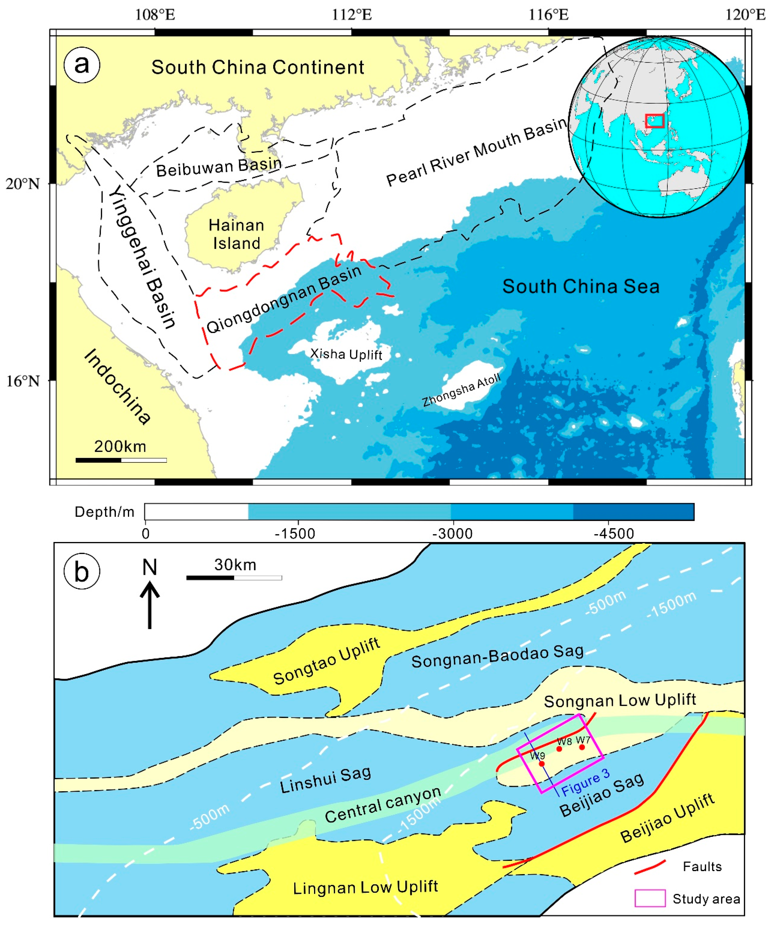
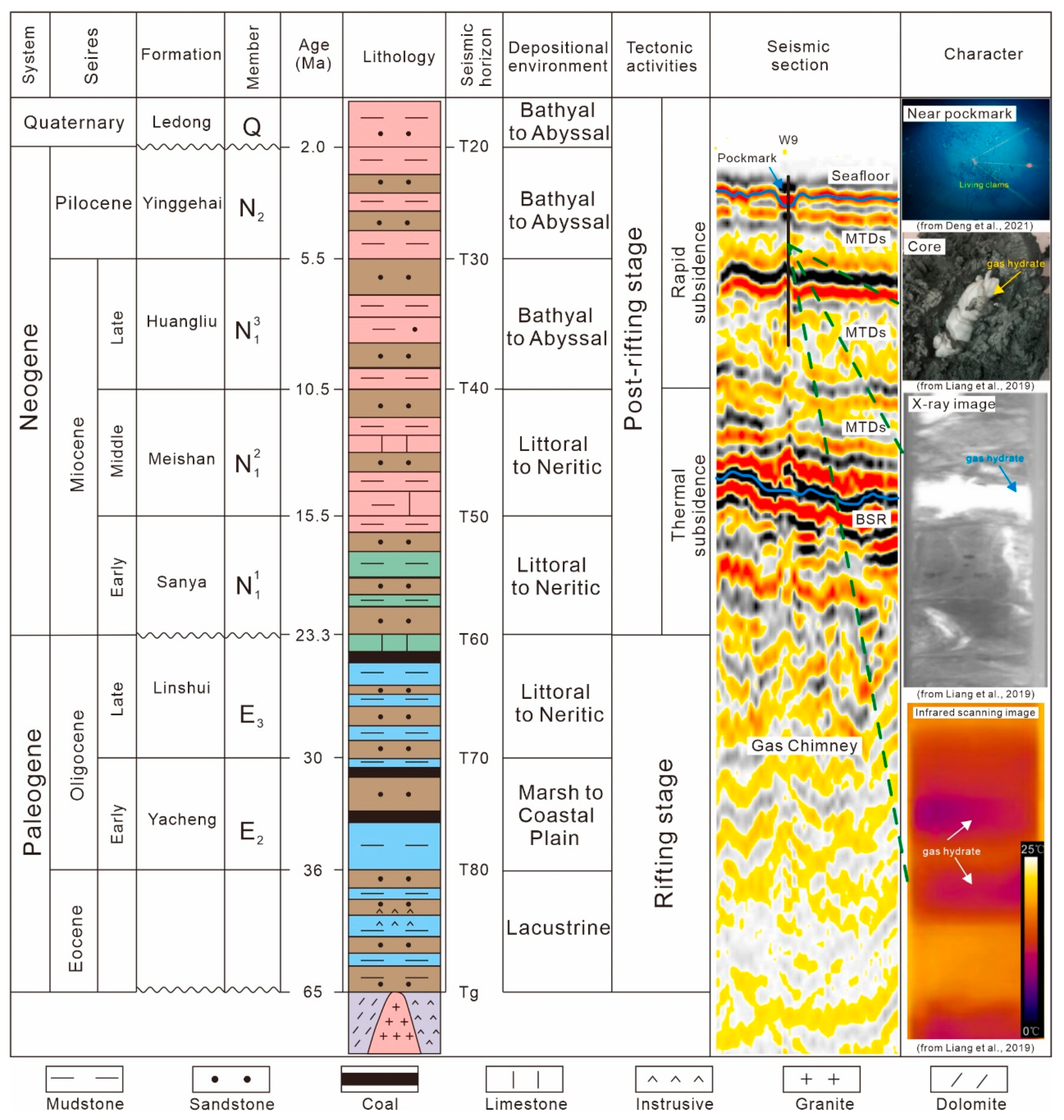
2. Geological Setting

The QDNB is a Cenozoic rift basin situated on a Mesozoic basement within the northern South China Sea (Figure 1), which is the largest marginal sea in the Western Pacific [23,24]. This basin underwent two distinct stages of structural evolution [25]: Eocene–Oligocene rifting and Neogene–Quaternary post-rifting (Figure 2). Due to this evolutionary process, the prevailing sedimentary environment within the QDNB transitioned from lacustrine during the early stage to shallow marine facies (embayment), and ultimately, to open marine and hemipelagic facies during the later stage [26]. Covering an approximate area of 65,000 km2, more than 60% of the basin is characterized by water depths exceeding 300 m [27]. The basin can be subdivided into five sub-level tectonic units: the Songnan-Baodao, Lingshui, and Beijiao sags, as well as the Songnan uplift and the Lingnan low uplifts [7]. The seafloor water temperature in the basin averages around 2–3 °C, while the average geothermal gradient measures approximately 40 °C/km, with localized variations due to heat flow activity [10,28].
In 2018 and 2019, the Guangzhou Marine Geological Survey conducted two drilling expeditions for gas hydrates. The results suggested that the QDNB has great potential as a source of gas hydrates [9,12]. The main hydrate sources in the QDNB are mixed gas sources composed of thermogenic and biogenic gases [8]. In recent years, studies have suggested that the thermogenic gas is mainly provided by the majority Paleogene source rocks in the mature–overmature stage, while the low-mature source rocks since the Late Miocene are the main source of the biogenic gas [5,10].
The study area is located roughly in the middle of the Songnan low uplift, with a water depth of 1200–1600 m. Gas chimneys and slender pipes are the most notable features of this area, and the vertical migration channels they form provide good conditions for the formation and accumulation of natural gas hydrates. The overpressure caused by the rapid filling of Cenozoic sediments in the QDNB is considered to be responsible for their generation [11,29,30].

3. Data and Methods

3.1. Data

In this study, three-dimensional (3D) seismic data covering an area of approximately 400 km2 were utilized. The data underwent post-stack time migration and were processed to achieve the zero-phase, with a spacing of 12.5 m and 25 m in the crossline and inline directions, respectively. The sampling interval of the 3D seismic data was 2 ms, and the dominant frequency was approximately 18 Hz, which increased to around 40 Hz within the zone of interest (2200–3500 ms), encompassing a total frequency band of about 2–100 Hz. GeoFrame and Petrel 2019 (Schlumberger, Houston, TX, USA) software were employed for the identification of gas chimneys, pipes, Bottom Simulating Reflectors (BSRs), and seismic reflections related to gas hydrates in the 3D seismic data, which offered superior horizontal and vertical resolution compared to 2D data. The presence of black–red–black or blue–red–blue seismic reflections indicated significant increases in acoustic impedance. The vertical resolution of the data varied with the depth but averaged around 8 m within the zone of interest (Figure 3).
For this study, data from three representative sites, namely W8, W10, and W9, located within three gas chimneys, were collected and analyzed [10,11]. The logging-while-drilling (LWD) data from the three wells primarily consisted of the gamma ray (GR), resistivity curve (RES), density curve (DEN), acoustic curve (AC), and P-wave velocity curve (P-velocity). These data proved to be valuable in identifying the occurrence of gas hydrates.

3.2. Methods

Based on the analysis of the seismic response characteristics, well logs, and prior research conducted in the area, interpretations were conducted for stratigraphy, fluid pathways, the Bottom Simulating Reflector (BSR), and shallow gas reservoirs. The interpretation schemes for stratigraphy and the regional stratigraphic framework were based on previous works [4,26]. The interpretations of different fluid pathways relied primarily on their distinct seismic response characteristics, supplemented by auxiliary analysis of their seismic attributes. The BSR identification and interpretation were carried out by integrating the simulation results of the base of the gas hydrate stability zone (BGHSZ) with the seismic reflection features. Shallow gas reservoirs were identified and interpreted based on the time-depth relationships and high-amplitude, negative-polarity seismic reflection features.
To determine the depth of the BSR, simulations of the BGHSZ were performed using the CSMHYD software [31], based on the seafloor temperature and geothermal gradient parameters at stations W8 and W9. Previous investigations in the area indicated a seafloor temperature of 3 °C, with geothermal gradients of 102 °C/km and 113 °C/km at W8 and W9, respectively [2,10]. The BSR, which serves as the interface between hydrates and underlying free gas, exhibited high-amplitude and negative-polarity seismic reflections. As the depth of the BGHSZ varied with different gas compositions, we assumed pure methane and a salinity of 3.5% during modeling to obtain the minimum depth of the BGHSZ in the area.
Seismic attribute maps and variance volume slices were utilized to identify the extent of the fluid pathways at different time depths. The boundaries of the structural faults, polygonal faults, and mass-transport deposits (MTDs) were clearly delineated on variance volume slices (Figure 4, Figure 5 and Figure 6). The low-amplitude and low-frequency characteristics of the gas chimneys on the seismic profiles were employed to characterize their extent using arc length attribute maps calculated within a 5 ms window above and below the T20 horizon. Moreover, the chaotic reflection features within the gas chimneys made their extent discernible on the variance volume slices as well.

4. Results

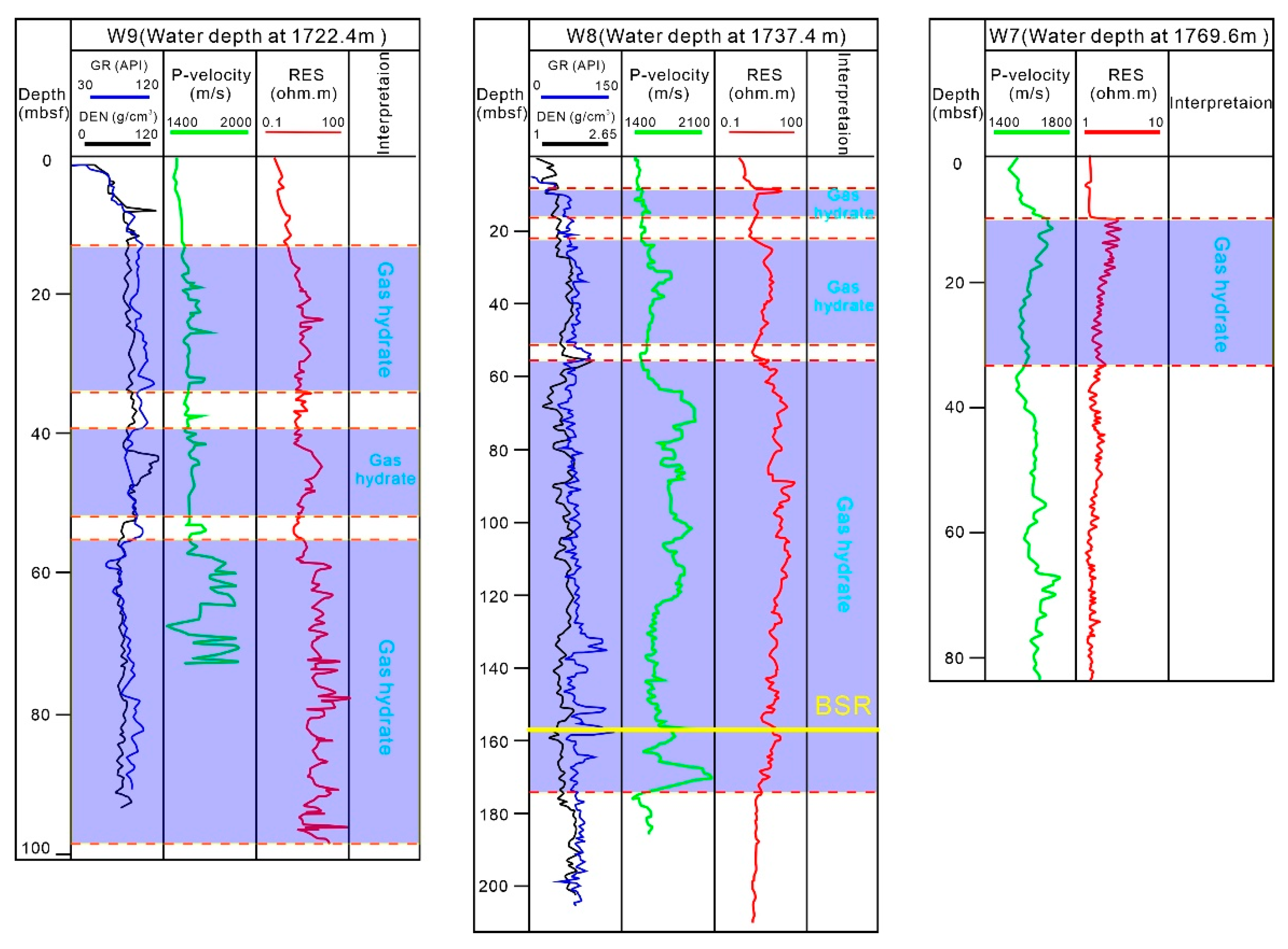
4.1. Seismic Stratigraphy and Gas Hydrates
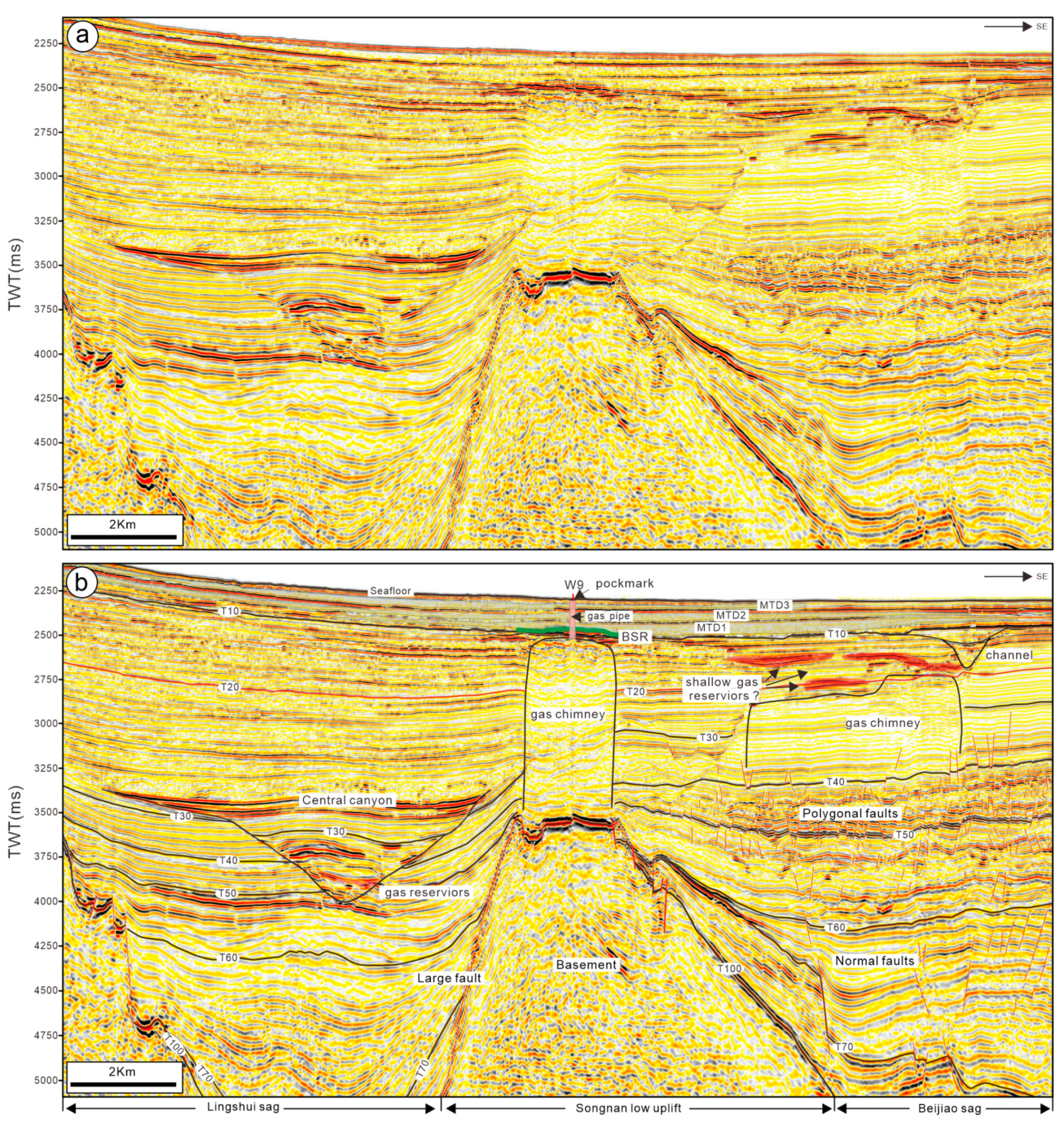
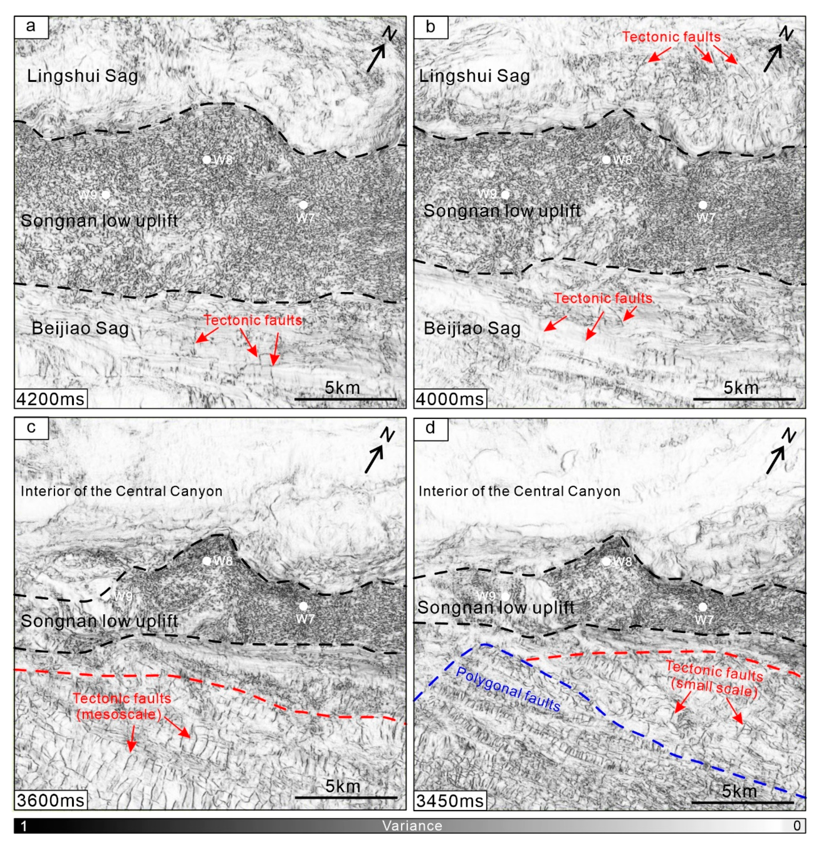
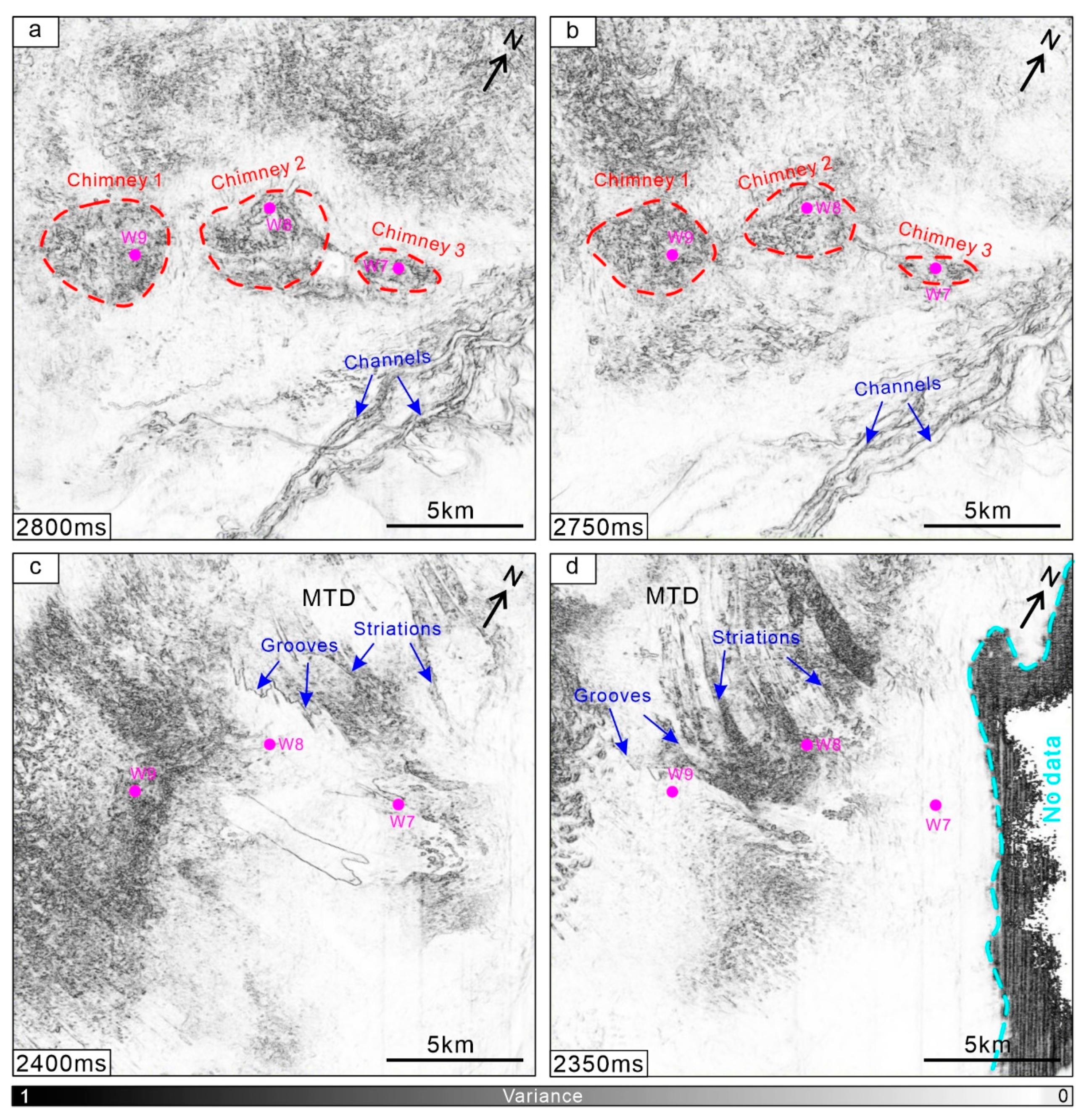
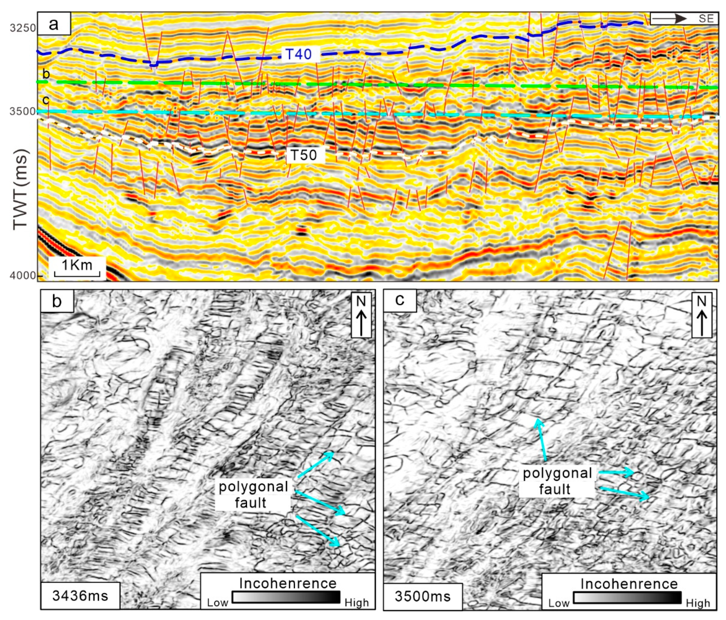
We identified eight reflections within the study area (Figure 3), with seven representing the top or bottom surfaces of regional formations and one representing the base of the MTD at the T10 horizon (Figure 2 and Figure 7). The hydrate reservoir in the study area is situated in the shallow Leidong Formation (from the seafloor to the T20 horizon), while the source rock is found in the deeper Yacheng Formation (from the T70 to the T100) (Figure 1 and Figure 2). Above the T20 horizon, there are three sets of MTDs that serve as reservoirs, with gas hydrates filling the fractures within them.
Analysis of the core samples, X-ray images, and thermal imaging photos in Figure 1 revealed that the hydrate type in the study area is fracture-filling hydrate. The hydrate reservoir primarily consists of fine-grained muddy sandstones, characterized by higher gamma values in the well log curves. The distribution of hydrates within the study area displays significant heterogeneity, as evident from the well log response curves at the three stations (Figure 8). At site W9, three intervals of hydrate-bearing formations with a total thickness of approximately 60 m (the total length of the well log data is about 98 m) are observed. Similarly, site W8 also exhibits three intervals of hydrate-bearing formations with a total thickness of approximately 150 m (the total length of the well log data is larger than 200 m). In contrast, site W7 has only one interval of hydrate-bearing formation, approximately 20 m thick (the total length of the well log data is about 84 m). Furthermore, it is worth noting that the maximum resistivity values at both the W9 and W8 sites exceed 100 Ω·m, whereas the maximum resistivity value at site W7 is below 10 Ω·m (Figure 8). This discrepancy in the resistivity values suggests that the W7 station exhibits the lowest hydrate saturation among the three sites [8].

4.2. Fluid Pathways

Based on the acquired 3D seismic data, well data, and previous research conducted in the area, a comprehensive analysis has revealed the identification of fluid pathways within the study area, spanning from the deep basement to the shallow seafloor. The fluid pathways can primarily be categorized into five types: tectonic faults, polygonal faults, gas chimneys, gas pipes, and fractures within mass transportation deposits (Figure 3, Figure 4, Figure 5, Figure 6, Figure 9 and Figure 10).
The tectonic faults predominantly comprise normal faults of varying scales (Figure 3 and Figure 4). Within the Songnan low uplift, listric faults demarcate the boundaries of the uplift [4]. In the deeper section (>4000 ms), the prevalence of tectonic faults is primarily attributed to large-scale normal faults, albeit their quantity is relatively lower compared to the mid-deep region (Figure 4a,b). Within the mid-deep region (3400–4000 ms), the normal faults within the Beijiao Sag are extensively developed, diminishing in scale as they approach shallower depths. However, due to the seismic section intersecting the central canyon of the Lingshui Sag, the normal faults within the Lingshui Sag are scarcely discernible on the seismic slice (Figure 4c,d). Furthermore, there exists a disparity in the distribution density of the normal faults on both sides of the Songnan low uplift, with a significantly higher density observed in the Beijiao Sag on the eastern side, as opposed to the Lingshui Sag on the western side. This discrepancy may suggest a greater intensity of fluid activity within the Beijiao Sag relative to the Lingshui Sag.
Figure 4. Different time slices of the variance volume illustrating the characteristics of the fluid pathways in the study area from deep to central, including the 4200 ms slice (a), 4000 ms slice (b), 3600 ms slice (c), and 3450 ms slice (d). The extent of the Songnan low uplift is delineated by the black dashed circle, while the areas with polygonal faults and tectonic faults are delineated by the blue dashed circle and red dashed circle, respectively.
Jmse 12 00659 g004
Figure 5. Different time slices of the variance volume revealing the features of the fluid pathways in the study area from central to shallow, including the 2800 ms slice (a), 2750 ms slice (b), 2400 ms slice (c), and 2350 ms slice (d). The range of chimneys is indicated by the red dashed line, and the erosional features of the MTD are also marked in this figure.
Jmse 12 00659 g005
Figure 6. Sectional and planar characteristics of the polygonal faults. The seismic profile in (a) displays the seismic features of the polygonal faults in the Meishan Formation stratigraphy, with the location of time slices at 3436 ms (b) and 3500 ms (c) identified by green and blue dashed lines, respectively.
Jmse 12 00659 g006
Figure 7. (a) Uninterpreted seismic profile. (b) Reflection interpretation of the BSR (Bottom Simulating Reflection). (c) Results of the gas hydrate stability zone modeling at sites W8 and W9. The location of this profile is shown in Figure 9.
Jmse 12 00659 g007
Figure 8. Logging characteristics of the gas hydrate-bearing layers in the three wells. The depth of the BSR (Bottom Simulating Reflection) exceeds the depth of the logging curves obtained at sites W9 and W7. The location of the BSR is marked by the solid yellow line in site W8.
Jmse 12 00659 g008
Figure 9. Arc-length attribute map along the T20 horizon illustrating the gas chimneys characterized by low values. The extent of the BSR, identified based on the modeling results of the base of the gas hydrate stability zone and seismic reflection features, is also displayed on this attribute map.
Jmse 12 00659 g009
The polygonal faults are predominantly distributed within the Meishan Formation (T40–T50) in the Beijiao Sag (Figure 3 and Figure 6). Their seismic reflection characteristics manifest as small-scale normal faults intersecting the formations in various directions. On the coherence slices, their distribution appears as polygons, such as quadrilaterals (Figure 6c) and pentagons (Figure 6b). Polygonal faults exhibit a widespread distribution in submarine formations globally and are widely acknowledged as preferential pathways for fluid migration [32,33,34,35,36], which is consistent with the conclusions of previous studies in the region [10,11]. The time-depth range of the polygonal faults is estimated to be 3300–3600 ms, with their left portion connecting to the gas chimneys and their upper part linking to the low-amplitude formations (Figure 11c).
Gas chimneys represent the primary vertical pathways for fluid concentration and migration in the area. Their seismic reflection characteristics exhibit low amplitude reflections from truncated formations, with pull-down reflections observed along their boundaries on the seismic profiles (Figure 10b). The distribution of the four gas chimneys varies with the time-depth, with the largest one occurring near T20. The area at T20 is used to show the extent of the gas chimneys (Figure 9).
Figure 10. (a) Uninterpreted seismic profiles depicting the seismic features of the gas chimneys, BSRs, and shallow gas reservoirs. (b) Enlargement showcasing the typical seismic features of the gas chimneys under site W9. (c) Enlargement highlighting the shallow gas reservoirs characterized by high-amplitude reflections with negative polarity. It is noteworthy that the shallow gas reservoirs are all located beneath the BSR. BSR, Bottom Simulating Reflection; HAR, high-amplitude reflection; MTD, mass transportation deposit.
Jmse 12 00659 g010
Pipes are primarily situated above the gas chimneys, connecting the seafloor pockmarks. They serve as the main pathways for fluid escape to the seafloor and are also accountable for the formation of pockmarks [10]. In the shallow portion of the study area, three sets of MTDs are present, and their erosional features can be identified on the variance volume slices (Figure 5c,d). Previous studies have indicated that fractures within MTDs are the primary spaces for the formation of gas hydrates [10].

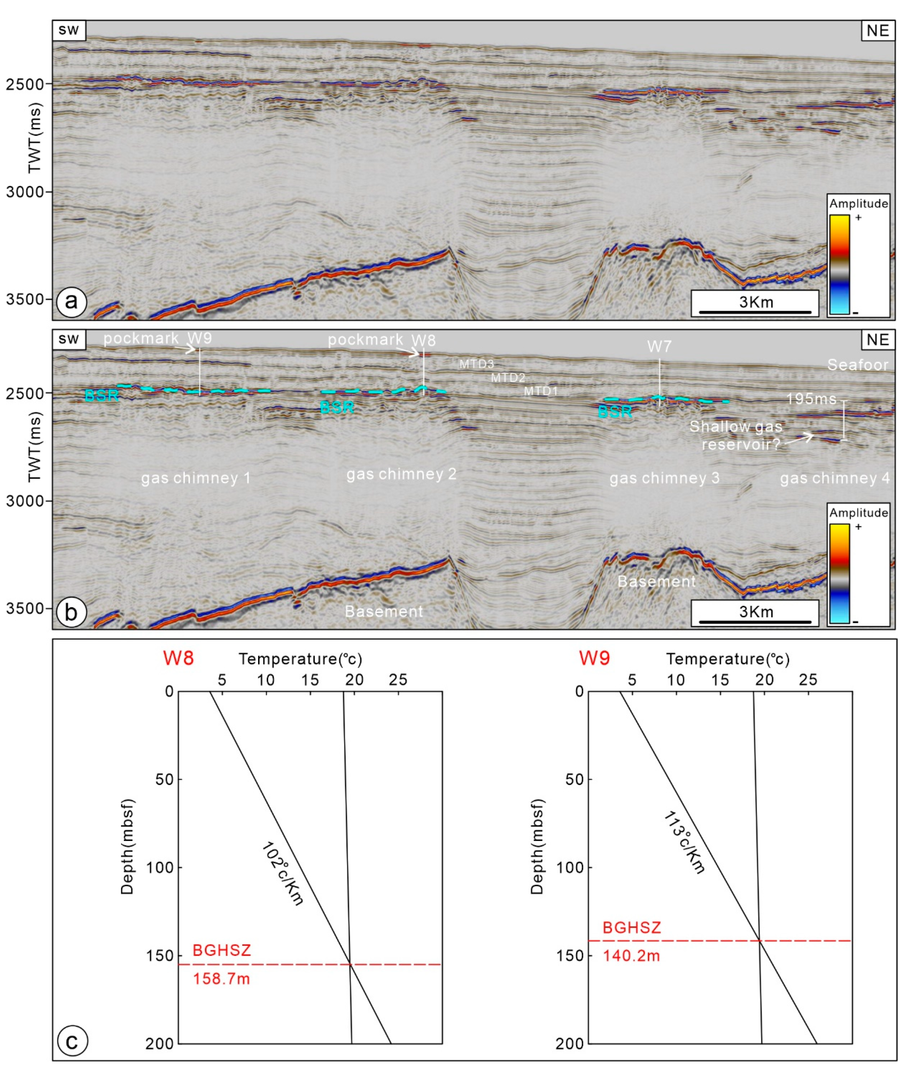
4.3. BSR and Shallow Gas Reservoirs

In the study area, identifying the BSR based solely on its seismic reflection characteristics presents a challenge due to the morphology of the BSR, which is nearly parallel to the stratigraphy rather than obliquely crossing it. Therefore, modeling of the BGHSZ was conducted to assist in determining the BSR. The simulation results indicate that at the W8 station, with a seafloor temperature of 3 °C and a geothermal gradient of 102 °C/km [2], the estimated depth of the BGHSZ is 158.7 mbsf. At the W9 station, with a seafloor temperature of 3 °C and a geothermal gradient of 113 °C/km [10], the estimated depth of the BGHSZ is 140.2 mbsf. Based on these findings, the interpretation of the BSR was completed, and its time-depth range was determined to be 2688–2759 ms (Figure 12). The spatial distribution of the BSR exhibits a strong coupling with the planar extent of the gas chimneys (Figure 9), suggesting a potential controlling effect of the gas chimneys on the formation of the BSR.
Figure 11. Planar coupling relationship between the shallow gas reservoirs, BSR, and fluid pathways. The planar distribution characteristics of the shallow gas reservoirs and fluid channels at different time depths, including 3600 ms (a) and 3450 ms (b). Interpreted seismic profiles through four shallow gas reservoirs are shown in (c). BSR, Bottom Simulating Reflector; HAR, high-amplitude reflection; LAR, low-amplitude reflection; MTD, mass transport deposit.
Jmse 12 00659 g011
Four shallow gas reservoirs are identified in the study area, named from west to east as shallow gas reservoir (SGR) 1, SGR2, SGR3, and SGR4 (Figure 11). These shallow gas reservoirs are characterized by low-amplitude reflections and negative polarity (Figure 10). Three of them are situated in the Beijiao Sag, while the remaining one is located above the Songnan low uplift, indicating the relatively higher maturity of the source rocks in the Beijiao Sag. The distribution of the three shallow gas reservoirs in the Beijiao Sag is predominantly located above areas of tectonic faults and polygonal faults, and the distribution of the shallow gas reservoir above the Songnan low uplift is primarily located above gas chimney 4 (Figure 11), suggesting a controlling effect of fluid pathways on the formation of shallow gas reservoirs. Furthermore, based on the spatial distribution of the shallow gas reservoirs and the BSR, all four shallow gas reservoirs are positioned below the BSR. SGR1 and SGR2 are located 133 ms below the BSR, while SGR3 and SGR4 are positioned 255 ms and 195 ms below the BSR, respectively (Figure 12).

5. Discussion

5.1. The Relationship between the BSR, Gas Hydrates and Gas Chimney

The close relationship between the Bottom Simulating Reflector and hydrates is difficult to deny. In many studies, the BSR in seismic profiles is often used as an indicator of hydrate presence, and the identified distribution range of the BSR is generally considered to represent the approximate range of hydrates [37,38,39]. However, based on the statistical analysis of 788 well data and the BSR, it was pointed out that the presence of the BSR does not necessarily indicate the presence of hydrates [40]. Nevertheless, the likelihood of encountering hydrates is significantly higher in areas where the BSR is present, and the thickness and saturation of the hydrate reservoirs in those areas are also greater. Previous studies have demonstrated that in this region, the BSR effectively indicates the presence of hydrates, primarily distributed within the fractures of the three sets of MTDs above the BSR [2,4,8,10,11].
As depicted in Figure 9, the distribution ranges of the BSR and gas chimneys exhibit a high degree of coincidence. Furthermore, previous researchers have revealed, through forward modeling and inversion results, that hydrates primarily accumulate in the pipes above the gas chimneys and in their vicinity [8,41]. These findings indicate that gas chimneys, serving as concentrated vertical pathways for deep fluids, exert a significant influence on the distribution of hydrates. It is worth noting that not all four gas chimneys are associated with a BSR. For instance, gas chimney 4 lacks a BSR above it but instead features SGR4 (Figure 12). Its top is approximately 195 ms in time depth below the other BSRs (Figure 7), which may be the reason why a BSR cannot be formed.

5.2. The Distribution Differences of the Shallow Gas Reservoirs and Fluid Pathways

Shallow gas reservoirs exert a significant impact on the accumulation of gas hydrates. In seismic reflection data, they are typically characterized by shallow reflections with reverse polarity and anomalous amplitudes [14,21,42]. Based on the seismic characteristics of shallow gas reservoirs (Figure 10), we have identified four such reservoirs in the study area and illustrated their distribution in Figure 11. The results indicate a controlled distribution pattern. Three out of the four shallow gas reservoirs (SGR1, SGR2, SGR3) are located above the northern reef depression, while the remaining reservoir (SGR4) is situated above the Songnan low uplift. Notably, no shallow gas reservoirs are present above the Lingshui Sag (Figure 11). To better understand the significant differences in the distribution of the shallow gas reservoirs within these two Sags, we conducted a study on the spatial coupling between the shallow gas reservoirs and fluid pathways. The results reveal that the three shallow gas reservoirs (SGR1–3) in the Beijiao Sag are precisely positioned above areas characterized by tectonic fault and polygonal fault development. and SGR4 is located above gas chimney 4 (Figure 11), indicating a close relationship between the distribution of the shallow gas reservoirs and these fluid pathways in this area.
There is a significant difference in the development of tectonic faults between the Lingshui Sag and the Beijiao Sag. The density of tectonic faults in the Beijiao Sag is much higher than in the Lingshui Sag (Figure 4a,b). Polygonal faults are considered important fluid pathways that strongly influence fluid migration and differential accumulation [10,13,14]. Additionally, tectonic faults have a significant impact on the growth of polygonal faults [13]. All the polygonal faults in the study area are located within the Beijiao Sag (Figure 11a,b). Globally, polygonal faults are primarily formed in shallow, fine-grained sediments and often facilitate vertical fluid migration [36,43,44] while preventing the lateral fluid migration [45,46,47]. This factor could potentially account for the substantial variations in the planar distribution of the shallow gas reservoirs observed between the two sags. Furthermore, the consistency between the position of SGR4 and gas chimney 4 also suggests a controlling effect of the gas chimney on the formation of SGR4 (Figure 11a,b).

5.3. Fluid Pathways with Gas Hydrates and Shallow Gas Reservoirs

Based on various data and analyses, previous studies conducted in the Qiongdongnan Basin have established different models for hydrate accumulation [10,11,38]. These models share three common understandings regarding hydrate accumulation in the region: (1) shallow biogenic gas and deep thermogenic gas jointly contribute to the gas source for hydrates, (2) gas chimneys influence the distribution of hydrates, and (3) hydrate reservoirs consist of fine-grained sediments. Notably, these established models exhibit similarities with the hydrate accumulation models in mud sediments summarized by [48,49,50]. However, these models overlook the influence of the shallow gas reservoirs on the hydrate system, which is an important aspect of gas hydrate systems for both exploration and development [13,14,39].
In the study area, a total of four shallow gas reservoirs are present (Figure 11). Although chemical analysis tests of the shallow gas reservoirs are lacking, their spatial distribution in relation to the fluid pathways exhibits a high level of consistency. This suggests that the gas source for the shallow gas reservoirs may primarily originate from the deep Yacheng Formation. All four shallow gas reservoirs (SGR1–4) are located below the BSR. SGR1 and SGR2 are positioned 133 ms below the BSR, while SGR3 and SGR4 are situated 255 ms and 195 ms below the BSR, respectively (Figure 12). These four shallow gas reservoirs are all found in areas characterized by well-developed fluid pathways, indicating an adequate gas supply. However, they are unable to form the BSR, which serves as a reflection of the hydrate bottom boundary. This may be due to the limited upward extension of these fluid pathways, making it challenging for the gas to reach the minimum depth required for hydrate formation. Instead, the gas accumulates in the sediment beneath the BSR, forming shallow gas reservoirs. In summary, the spatial coupling between the fluid pathways, shallow gas reservoirs, and the BSR suggests that in the study area, the fluid pathways exert control over the distribution of the shallow gas reservoirs, and the distribution of hydrates or the BSR is not solely dependent on the density of the fluid pathways but also on the distance between the top of the fluid pathways and the base of the gas hydrate stability zone (Figure 12).

6. Conclusions

1. Gas chimneys exert a significant influence on the distribution of hydrates, although all four gas chimneys are not associated with the BSR.
2. The spatial distribution relationship between the shallow gas reservoirs and fluid pathways indicates that the gas source for the shallow gas reservoirs may primarily originate from the deep Yacheng Formation.
3. Fluid pathways control the distribution of shallow gas reservoirs, and their distribution range and density result in significant differences in the distribution of the shallow gas reservoirs in the Beijiao Sag and Lingshui Sag.
4. The interplay among the fluid pathways, shallow gas reservoirs, and the BSR indicates that the fluid pathways play a significant role in determining the distribution of the shallow gas reservoirs. Additionally, the distribution of hydrates and the BSR is influenced not only by the density of fluid pathways but also by the vertical distance between the top of the fluid pathways and the base of the gas hydrate stability zone.
Based on the three-dimensional seismic data from the Qiongdongnan Basin, we have identified the spatial distribution of the fluid pathways, shallow gas reservoirs, and the BSR within the region. Furthermore, we have elucidated the coupling relationship between them. This finding may contribute to the exploration and development of gas hydrates and shallow gas reservoirs.

Author Contributions

Conceptualization, S.W. (Songlin Wu), J.S., J.C. and U.K.; Methodology, S.W. (Songlin Wu) and J.C.; Software, S.W. (Songlin Wu), S.W. (Shiguo Wu), Q.L., J.C. and Y.C.; Validation, J.S., Y.C. and X.Z.; Formal analysis, S.W. (Songlin Wu); Investigation, S.W. (Songlin Wu), J.C., Y.C., X.Z. and U.K.; Resources, S.W. (Shiguo Wu) and Q.L.; Data curation, S.W. (Songlin Wu), S.W. (Shiguo Wu), J.S., Q.L., Y.C. and U.K.; Writing—original draft, S.W. (Songlin Wu); Writing—review & editing, S.W. (Songlin Wu); Supervision, J.S. and X.Z.; Project administration, S.W. (Shiguo Wu) and Q.L.; Funding acquisition, S.W. (Shiguo Wu) and J.S. All authors have read and agreed to the published version of the manuscript.

Funding

This study was funded by the National Natural Science Foundation of China (U22A20581), Sanya Science and Technology Special Fund (2022KJCX64), Hainan Provincial Natural Science Foundation of China (NO.422QN354), Hainan Provincial Natural Science Foundation of China (422RC746, 421QN0908), The Innovation Platform for Academicians of Hainan Province (YSPTZX202204), and Hainan Provincial Natural Science Foundation of China (No. 422QN355).

Institutional Review Board Statement

Not applicable.

Informed Consent Statement

Not applicable.

Data Availability Statement

Data are contained within the article.

Acknowledgments

We gratefully acknowledge the China National Offshore Oil Company for providing the seismic and geological data used in this paper.

Conflicts of Interest

Author Qingping Li was employed by the company China National Offshore Oil Corporation. The remaining authors declare that the research was conducted in the absence of any commercial or financial relationships that could be construed as a potential conflict of interest.

References

  1. Collett, T.S.; Boswell, R.; Waite, W.F.; Kumar, P.; Roy, S.K.; Chopra, K.; Singh, S.K.; Yamada, Y.; Tenma, N.; Pohlman, J.; et al. India national gas hydrate program expedition 02 summary of scientific results: Gas hydrate systems along the eastern continental margin of India. Mar. Petrol. Geol. 2019, 108, 39–142. [Google Scholar] [CrossRef]
  2. Ye, J.L.; Wei, J.G.; Liang, J.Q.; Lu, J.A.; Lu, H.L.; Zhang, W. Complex gas hydrate system in a gas chimney. South China Sea. Mar. Pet. Geol. 2019, 104, 29–39. [Google Scholar] [CrossRef]
  3. Suess, E. Marine cold seeps and their manifestations: Geological control, biogeochemical criteria and environmental conditions. Int. J. Earth Sci. 2014, 103, 1889–1916. [Google Scholar] [CrossRef]
  4. Wang, J.; Li, A.; Wang, L.; Wu, S.; Li, Q. Submarine fluid flow system feeding methane emission in the northern South China Sea. Basin Sci. 2023, 168, 17–26. [Google Scholar] [CrossRef]
  5. Huang, H.; Huang, B.; Huang, Y.; Li, X.; Tian, H. Condensate origin and hydrocarbon accumulation mechanism of the deepwater giant gas field in western South China Sea: A case study of Lingshui 17–2 gas field in Qiongdongnan Basin. Pet. Explor. 2017, 44, 409–417. [Google Scholar] [CrossRef]
  6. Xie, Y.; Zhang, G.; Sun, Z.; Zeng, Q.; Zhao, Z.; Guo, S. Reservoir forming conditions and key exploration technologies of Lingshui 17–2 giant gas field in deepwater area of Qiongdongnan Basin. Petrol. Res. 2019, 4, 1–18. [Google Scholar] [CrossRef]
  7. Fang, Y.; Wei, J.; Lu, H.; Liang, J.; Lu, J.A.; Fu, J.; Cao, J. Chemical and structural characteristics of gas hydrates from the Haima cold seeps in the Qiongdongnan Basin of the South China Sea. J. Asian Earth Sci. 2019, 182, 103924. [Google Scholar] [CrossRef]
  8. Deng, W.; Liang, J.; Zhang, W.; Kuang, Z.G.; Zhong, T.; He, Y.L. Typical characteristics of fracture-filling hydrate-charged reservoirs caused by heterogeneous fluid flow in the Qiongdongnan Basin, northern south China Sea. Mar. Pet. Geol. 2021, 124, 104810. [Google Scholar]
  9. Zhang, W.; Liang, J.; Qiu, H.; Wei, D.; Meng, M. Double bottom simulating reflectors and tentative interpretation with implications for the dynamic accumulation of gas hydrates in the northern slope of the Qiongdongnan Basin, South China Sea. J. Asian Earth Sci. 2022, 229, 105–151. [Google Scholar] [CrossRef]
  10. Liang, J.; Zhang, W.; Lu, J.; Ren, J.; Kuang, Z.; He, Y. Geological occurrence and accumulation mechanism of natural gas hydrates in the eastern Qiongdongnan Basin of the South China Sea: Insights from Site GMGS5-W9–2018. Mar. Geol. 2019, 418, 10604. [Google Scholar] [CrossRef]
  11. Zhang, W.; Liang, J.; Meng, M.; He, Y.L.; Deng, W.; Feng, J.X. Characteristics and controlling mechanism of typical leakage gas hydrate reservoir forming system in the Qiongdongnan Basin, northern South China Sea. Nat. Gas Ind. 2020, 40, 90–98, (In Chinese with English abstract). [Google Scholar]
  12. Meng, M.; Liang, J.; Lu, J.; Zhang, W.; Kuang, Z.; Fang, Y.; He, Y.; Deng, W.; Huang, W. Quaternary deep-water sedimentary characteristics and their relationship with the gas hydrate accumulations in the Qiongdongnan Basin, Northwest South China Sea. Deep. Sea Res. I 2021, 177, 103628. [Google Scholar] [CrossRef]
  13. Ostanin, I.; Anka, Z.; di Primio, R.; Bernal, A. Identification of a Large Upper Cretaceous Polygonal Fault Network in the Hammerfest basin:Implications on the Reactivation of Regional Faulting and Gas Leakage Dynamics, SW Barents Sea. Mar. Geol. 2012, 332, 109–125. [Google Scholar] [CrossRef]
  14. Müller, S.; Reinhardt, L.; Franke, D.; Gaedicke, C.; Winsemann, J. Shallow gas accumulations in the German North Sea. Mar. Petrol. Geol. 2018, 91, 139–151. [Google Scholar] [CrossRef]
  15. Schroot, B.M.; Schüttenhelm, R.T.E. Expressions of shallow gas in The Netherlands North Sea. Neth. J. Geosci. 2003, 82, 91–105. [Google Scholar] [CrossRef]
  16. Mazumdar, A.; Peketi, A.; Dewangan, P.; Badesab, F.; Ramprasad, T.; Ramana, M.V.; Patil, D.J.; Dayal, A. Shallow gas charged sediments off the Indian west coast: Genesis and distribution. Mar. Geol. 2009, 267, 71–85. [Google Scholar] [CrossRef]
  17. Fleischer, P.; Orsi, T.; Richardson, M.; Anderson, A. Distribution of free gas in marine sediments: A global overview. Geo Mar. Lett. 2001, 21, 103–122. [Google Scholar]
  18. Fu, X.; Jimenez-Martinez, J.; Nguyen, T.P.; Carey, J.W.; Viswanathan, H.; CuetoFelgueroso, L.; Juanes, R. Crustal fingering facilitates free-gas methane migration through the hydrate stability zone. Proc. Natl. Acad. Sci. USA 2020, 2020, 11064. [Google Scholar] [CrossRef]
  19. Heeschen, K.U.; Schicks, J.M.; Oeltzschner, G. The promoting effect of natural sand on methane hydrate formation: Grain sizes and mineral composition. Fuel 2016, 181, 139–147. [Google Scholar] [CrossRef]
  20. Verweij, J.M.; Nelskamp, S.N.; Ten Veen, J.H.; De Bruin, G.; Geel, K.; Donders, T.H. Generation, migration, entrapment and leakage of microbial gas in the Dutch part of the Southern North Sea Delta. Mar. Petrol. Geol. 2018, 97, 493–516. [Google Scholar] [CrossRef]
  21. Cox, D.R.; Huuse, M.; Newton, A.M.W.; Sarkar, A.D.; Knutz, P.C. Shallow gas and gas hydrate occurrences on the northwest Greenland shelf margin. Mar. Geol. 2021, 432, 106382. [Google Scholar] [CrossRef]
  22. Yang, L.; Ye, J.; Qin, X.; Liang, Q.; Wu, X. Effects of the seepage capability of overlying and underlying strata of marine hydrate system on depressurization-induced hydrate production behaviors by horizontal well. Mar. Petrol. Geol. 2021, 128, 105019. [Google Scholar] [CrossRef]
  23. Xie, X.; Müller, R.D.; Li, S.; Gong, Z.; Steinberger, B. Origin of anomalous subsidence along the Northern South China Sea margin and its relationship to dynamic topography. Mar. Pet. Geol. 2006, 23, 745–765. [Google Scholar] [CrossRef]
  24. Sun, Q.; Wu, S.; Cartwright, J.; Dong, D. Shallow gas and focused fluid flow systems in the Pearl River Mouth Basin, northern South China Sea. Mar. Geol. 2012, 315, 1–14. [Google Scholar] [CrossRef]
  25. Zhao, Z.X.; Sun, Z.; Wang, Z.F.; Sun, Z.P.; Liu, J.B.; Zhang, C.M. The high re-solution sedimentary filling in Qiongdongnan Basin, Northern South China Sea. Mar. Geol. 2015, 361, 11–24. [Google Scholar] [CrossRef]
  26. Lai, H.; Fang, Y.; Kuang, Z.; Ren j Liang, J.; Lu, J.; Wang, G.; Xing, C. Geochemistry, origin and accumulation of natural gas hydrates in the qiongdongnan basin, south china sea: Implications from site GMGS5-W08. Mar. Pet. Geol. 2021, 123, 104774. [Google Scholar] [CrossRef]
  27. Wang, Z.F.; Sun, Z.P.; Zhu, J.T.; Guo, M.G.; Jiang, R.F. Natural gas geological characteristics and great discovery of large gas fields in deep-water area of the western South China Sea. Nat. Gas Ind. B 2015, 2, 489–498. [Google Scholar] [CrossRef]
  28. Yuan, Y.S.; Zhu, W.L.; Mi, L.J.; Zhang, G.C.; Hu, S.B.; He, L.J. “Uniform geothermal gradient” and heatflow in the Qiongdongnan and Pearl River Mouth Basins of the South China Sea. Mar. Pet. Geol. 2009, 26, 1152–1162. [Google Scholar] [CrossRef]
  29. Shi, W.Z.; Xie, Y.H.; Wang, Z.F.; Li, X.S.; Tong, C.X. Characteristics of overpressure distribution and its implication for hydrocarbon exploration in the Qiongdongnan Basin. J. Asian Earth Sci. 2013, 66, 150–165. [Google Scholar] [CrossRef]
  30. Wang, X.J.; Wu, S.G.; Yuan, S.Q.; Wang, D.W.; Ma, Y.B.; Yao, G.S.; Gong, Y.H.; Zhang, G.X. Geophysical signatures associated with fluid flow and gas hydrate occurrence in a tectonically quiescent sequence, Qiongdongnan Basin, South China Sea. Geofluids 2010, 10, 351–368. [Google Scholar] [CrossRef]
  31. Sloan, E.D., Jr.; Koh, C.A. Clathrate Hydrates of Natural Gases; CRC Press: Boca Raton, FL, USA, 2007. [Google Scholar]
  32. Hustoft, S.; Mienert, J.; Bünz, S.; Nouzé, H. High-resolution 3D Seismic Data Indicate Focused Fluid Migration Pathways above Polygonal Fault Systems of the Mid-Norwegian Margin. Mar. Geol. 2007, 245, 89–106. [Google Scholar] [CrossRef]
  33. Sun, Q.; Wu, S.; Lü, F.; Yuan, S. Polygonal Faults and Their Implications for Hydrocarbon Reservoirs in the Southern Qiongdongnan Basin, South China Sea. J. Asian Earth Sci. 2010, 39, 470–479. [Google Scholar] [CrossRef]
  34. Laurent, D.; Gay, A.; Baudon, C.; Berndt, C.; Soliva, R.; Planke, S.; Mourgues, R.; Lacaze, S.; Pauget, F.; Mangue, M.; et al. High-resolution Architecture of a Polygonal Fault Interval Inferred from Geomodel Applied to 3D Seismic Data from the Gjallar Ridge, Vøring Basin, Offshore Norway. Mar. Geol. 2012, 332, 134–151. [Google Scholar] [CrossRef]
  35. Tewksbury, B.J.; Hogan, J.P.; Kattenhorn, S.A.; Mehrtens, C.J.; Tarabees, E.A. Polygonal Faults in Chalk: Insights from Extensive Exposures of the Khoman Formation, Western Desert, Egypt. Geology 2014, 42, 479–482. [Google Scholar] [CrossRef]
  36. Alrefaee, H.A.; Ghosh, S.; Abdel-Fattah, M.I. 3D Seismic Characterization of the Polygonal Fault Systems and its Impact on Fluid Flow Migration: An Example from the Northern Carnarvon Basin, Australia. J. Pet. Sci. Eng. 2018, 167, 120–130. [Google Scholar] [CrossRef]
  37. Shedd, W.; Boswell, R.; Frye, M.; Godfriaux, P.; Kramer, K. Occurrence and nature of “bottom simulating reflectors” in the Northern Gulf of Mexico. Mar. Pet. Geol. 2012, 34, 31–40. [Google Scholar] [CrossRef]
  38. Zhang, W.; Liang, J.; Su, P. Distribution and characteristics of mud diapirs, gas chimneys, andbottom simulating reflectors associated with hydrocarbon migration and gas hydrate accumulation in the Qiongdongnan Basin, northern slope of the South China Sea. Geol. J. 2018, 54, 3556. [Google Scholar] [CrossRef]
  39. Ren, J.; Cheng, C.; Xiong, P.; Kuang, Z.; Liang, J.; Lai, H.; Chen, Z.; Chen, Y.; Li, T.; Jiang, T. Sand-rich gas hydrate and shallow gas systems in the Qiongdongnan Basin, northern South China Sea. J. Pet. Sci. Eng. 2022, 215, 110630. [Google Scholar] [CrossRef]
  40. Majumdar, U.; Cook, A.E.; Shedd, W.; Frye, M. The connection between natural gas hydrate and bottom-simulating reflectors. Geophys. Res. Lett. 2016, 43, 7044–7051. [Google Scholar] [CrossRef]
  41. Sun, L.; Li, Q.; Chen, F.; Yu, H.; Wang, X.; Jin, J. The numerical modelling analysis on the characteristics of multi-type gas hydrates occurrence in the mass transport deposit area, the Qiongdongnan Basin. Chin. J. Geophys. 2023, 66, 4721–4741, (In Chinese with English abstract). [Google Scholar]
  42. Aydin, H.; Merey, S. The effect of gas production from deeper conventional gas reservoirs on shallower gas hydrate layer stability: A case study in the conditions of the Sakarya gas field, Western Black Sea. J. Nat. Gas Sci. Eng. 2021, 94, 104103. [Google Scholar] [CrossRef]
  43. Ding, X.J.; Liu, G.D.; Sun, M.L.; Wang, P.G. Origin of Polygonal Fault Systems: A Case from the Sanzhao Sag in the Songliao Basin, East China. Pet. Explor. Dev. 2013, 40, 309–319. [Google Scholar] [CrossRef]
  44. Velayatham, T.; Holford, S.P.; Bunch, M.A.; King, R.C. Fault Controlled Focused Fluid Flow in the Ceduna Sub-Basin, Offshore South Australia; Evidence from 3D Seismic Reflection Data. Mar. Pet. Geol. 2021, 127, 104813. [Google Scholar] [CrossRef]
  45. He, C.; Tang, L.; Huang, D.; Shi, S. Polygonal Faults in the Sanzhao Sag of the Songliao basin: Their Significance in Hydrocarbon Accumulation. Min. Sci. Tech. 2010, 20, 300–305. (In Chinese) [Google Scholar] [CrossRef]
  46. Andresen, K.J.; Huuse, M. ’Bulls-eye’ Pockmarks and Polygonal Faulting in the Lower Congo Basin: Relative Timing and Implications for Fluid Expulsion during Shallow Burial. Mar. Geol. 2011, 279, 111–127. [Google Scholar] [CrossRef]
  47. Ilg, B.R.; Hemmings-Sykes, S.; Nicol, A.; Baur, J.; Fohrmann, M.; Funnell, R.; Milner, M. Normal Faults and Gas Migration in an Active Plate Boundary, Southern Taranaki Basin, Offshore New Zealand. Bulletin 2012, 96, 1733–1756. [Google Scholar] [CrossRef]
  48. You, K.; Flemings, P.B.; Malinverno, A.; Collett, T.S.; Darnell, K. Mechanisms of methane hydrate formation in geological systems. Rev. Geophys. 2019, 57, 1146–1196. [Google Scholar] [CrossRef]
  49. Collett, T.S.; Boswell, R.; Cochran, J.R.; Kumar, P.; Lall, M.; Mazumdar, A. Geologic implications of gas hydrates in the offshore of India: Results of the National Gas Hydrate Program Expedition 01. Mar. Pet. Geol. 2014, 58, 3–28. [Google Scholar] [CrossRef]
  50. Cook, A.E.; Goldberg, D.S.; Malinverno, A. Natural gas hydrates occupying fractures: A focus on non-vent sites on the Indian continental margin and the northern Gulf of Mexico. Mar. Pet. Geol. 2014, 58, 278–291. [Google Scholar] [CrossRef]
Figure 1. (a) The locations of sedimentary basins in the northern South China Sea, highlighting the Qiongdongnan basin (QDNB) with red lines [24]. (b) Schematic structure of the western part of the QDNB, based on [26,27], illustrating the study area and the locations of gas hydrate drilling wells. The location of Figure 3 is shown in Figure 1b.
Jmse 12 00659 g001
Figure 2. Comprehensive stratigraphic column of the Qiongdongnan Basin, incorporating the tectonic evolution, major stratigraphic units, and horizons [4,29]. The image also includes a seismic section near site W9, pictures of pockmarks at station W9, and pictures of various cores of hydrates in site W9, as documented by [8,10].
Jmse 12 00659 g002
Figure 3. Typical seismic profile crossing well W9, demonstrating the stratigraphic framework and primary fluid pathways from deep to shallow in the study area. The uninterpreted profile is shown in (a), while the interpreted profile is shown in (b).
Jmse 12 00659 g003
Figure 12. Spatial distribution of the shallow gas reservoirs, BSRs, and fluid pathways in a 3D view.
Jmse 12 00659 g012
Disclaimer/Publisher’s Note: The statements, opinions and data contained in all publications are solely those of the individual author(s) and contributor(s) and not of MDPI and/or the editor(s). MDPI and/or the editor(s) disclaim responsibility for any injury to people or property resulting from any ideas, methods, instructions or products referred to in the content.

