Abstract
Based on the effect of damped shear deformation on energy dissipation, a new constrained damping base for a polymer injection platform deck is proposed to reduce the excessive vibrations caused when multiple plunger pumps are jointly operated. A model for analyzing the vibration response of an I-beam-constrained damping base for a polymer injection platform with multiple plunger pumps was established using Abaqus 6.14 software and compared with rigid base and traditional rubber vibration isolators in terms of its vibration isolation performance. Furthermore, the effects of the damping material’s loss factor, the thickness of the damping layer, and the number of expansion layers on the vibration isolation characteristics of the constrained damping base were explored. This study shows that, with an increase in the damping material’s loss factor, the thickness of the damping layer and the number of extended layers, the vibration isolation performance of the constrained damping base is gradually enhanced. When the damping material’s loss factor is 1.0, the thickness of the damping layer is 20 mm, and the number of extended layers is 3, the constrained damping base’s vibration damping effect is optimized, and its vibration isolation rate becomes as high as 46.63%, which can significantly reduce the vibration response of the polymer injection platform.
1. Introduction
The use of plunger pumps to inject polymer into wells to enhance the oil content recovered is a common enhancement technique in the later stages of oilfield development. The high viscosity of the polymer results in a high output pressure in the plunger pump, leading to a significant excitation force. Consequently, when multiple plunger pumps are operated simultaneously during the polymer injection process, severe vibrations can occur on the platform deck. These vibrations have the potential to cause fatigue damage to the platform and pose a serious threat to the safety of both the platform and personnel. Therefore, it is crucial to conduct research on vibration response control technology for injection platforms subjected to the action of multiple plunger pumps. Additionally, developing vibration isolation bases with excellent performance is essential to ensure the structural safety of injection platforms.
The vibration control methods commonly used in engineering are mainly categorized into these three types of methods: passive control [1,2], semi-active control [3,4], and active control [5,6]. As typically used passive vibration isolation devices, rubber vibration isolators have the advantages of a simple structure, absorbing a substantial amount of energy, coming in various forms, and requiring no additional energy input, among other things, and are widely used in engineering. Jin et al. [7] studied the fatigue life of rubber vibration isolators using experimental methods, which provided an important basis for the design, operation, and maintenance of rubber vibration isolators. Rahnavard et al. [8,9] investigated the performance of steel–rubber vibration isolators under axial tension, compression, base shear, and the nature of the influence of the number and size of the rubber cores on the vibration damping performance of vibration isolators. Roncen et al. [10] conducted numerical simulations and experimental studies on the performance of nonlinear rubber vibration isolators under harmonic and random excitation to verify the temperature dependence of their mechanical properties. Wang et al. [11] experimentally investigated the nature of the influence of rubber vibration isolators’ dynamic stiffness on the dynamic performance of seawater piston pumps and found that the vibration response of the piston pump decreases with an increase in the dynamic stiffness of the rubber vibration isolator.
Kerwin [12] further proposed a constrained damping structure based on rubber vibration isolators and established a basic theory on the vibration damping in constrained damping structures. Constrained damping structures are widely used in the field of vibration and noise reduction in rail transportation, such as on railroads and aircraft. In light of this, Wei et al. [13] experimentally tested the peak acceleration of rails with and without damping plates and verified that constrained damping structures suppress rail vibrations. Zeng et al. [14] optimized conventional, constrained damped rails and proposed a wide-frequency labyrinth-type constrained damped rail that effectively reduced the vibrations and noise, which improved the service life of the wheels and rails. Similarly, Li et al. [15,16] used an experimental method to comparatively analyze the vibration response of rail structures with and without labyrinth-type constrained damping, verifying that labyrinth-type constrained damping rails reduced vibrations and noise efficiently in a wide frequency range. Levraea et al. [17] applied a constrained damping structure to the surface of an aircraft skin, which effectively reduced the local vibration of the skin and extended the service life of the aircraft. Gu et al. [18] used parameter optimization and experimental analysis to verify that constrained damping structures can effectively reduce the stress–strain amplitude within an aircraft’s typical cantilever beam structure. Of interest is the use of dead mass damping [19,20] to suppress vibration and the use of piezoelectric materials to harvest and suppress vibration energy [21,22,23] as preliminary vibration control methods.
Abundant scholarly research on damping and vibration damping for offshore platforms exists. For example, Wang et al. [24] controlled the vibrations occurring in jacket offshore wind turbines due to multihazards such as wind, waves, and earthquakes using an amplifying damping transfer system. Unlike traditional tuned mass dampers (TMDs), which may be less effective for higher modes, this ADTS provided additional damping in both the fundamental and higher modes of the JOWTs, resulting in better resistance to multiple hazards. Xia et al. [25] used a coupled simulation algorithm to investigate the vibration damping performance of semi-active particle damping technology in an offshore platform truss structure. The control strategy, the simulation algorithm, and the key parameters of the semi-active particle damping mechanism were investigated to analyze its attenuation of the vibrations in the offshore platform truss structure. Equally, Jin et al. [26] proposed using a damped vibration isolation system consisting of rubber bearings and viscous dampers to mitigate the vibrations of the JZ20-2MUQ steel-cased platform in the Bohai Sea. The influence of the key parameters of the damping isolation system on suppressing vibrations in the offshore structure was studied in detail. Furthermore, Sun et al. [27] designed an external outrigger damping system, which had a demonstrable damping effect for ice loads.
At present, the research on constrained damping structures has mainly focused on the field of vibration and noise reduction in rail transportation. In view of the excellent performance of such structures in terms of vibration and noise reduction, if they can be introduced into the field of offshore engineering and used to control and reduce the vibrations caused by plunger pumps, the vibrations on polymer injection platforms can be significantly reduced and their safety enhanced. When up to 11 sets of plunger pumps on offshore platforms are operated simultaneously, the vibration response is intense, and there is an urgent need to design a performant vibration isolation base that can be easily installed and economically applied. For efficient vibration reduction, it is necessary to further explore the influence of the relevant parameters of the constrained damping structure on its damping characteristics, according to which the design of the constrained damping base can be optimized to good effect.
In this paper, the existing constrained damping steel rail structures used for vibration and noise reduction in rail transportation are drawn upon. Subsequently, considering the vibration characteristics of the plunger pumps on offshore polymer injection platforms, a constrained damping base structure able to reduce large-magnitude vibrations is presented using the Abaqus 6.14 finite element software. This prototype is compared with rigid base and traditional rubber vibration isolators in terms of its vibration isolation performance. The influence of the damping layer’s loss factor, the damping layer’s thickness, and the number of expansion layers on the vibration damping performance of the base is further investigated, and a performant-constrained damped vibration damping base is finally designed to provide a useful reference for vibration control on a polymer injection platform.
2. Polymer injection Platform Structure and Constrained Damping Base
2.1. Polymer Injection Platform Structure
The polymer injection platform studied here is an in-service offshore platform owned by Sinopec Petroleum Engineering Design Co., Ltd. for China (Beijing, China). The structural dimensions and equipment data were provided by Sinopec, and a 1:1 numerical model was established to study the vibration response. The effect of the constrained damping base was tested on an eight-pile-leg polymer injection platform with a working water depth of 12.0 m, a total length of 48.0 m, a total width of 38.50 m, a total height of 46.70 m, and a total weight of 6382 t. In order to facilitate the analysis and calculation, the soil body’s constraint of the injection platform was simplified to 8 times the value of the pile diameter below the mud’s surface. The main parameters of the polymer injection platform are shown in Table 1, and the corresponding numerical model is shown in Figure 1.

Table 1.
Main parameters of the polymer injection platform.

Figure 1.
Numerical models of polymer injection platform and layout of lower deck. (a) Numerical models of polymer injection platform; (b) layout of lower deck.
2.2. Plunger Pump Excitation Simulation
According to the actual operational requirements, 11 sets of 3ZJ-50/15 triplex horizontal piston pumps were selected in this study, each of which is 4 m in length, 2.5 m in width, 2.6 m in height, and 15 t in weight, with a working pressure of 15 MPa, an output flow rate of 50 m3/h, a rated rotational speed of 175 rpm, and a frequency of 2.92 Hz. Their location and numbering are shown in Figure 1b. During its operation, the rotary movement of the crankshaft of the plunger pump is driven by a motor through a crank linkage mechanism. This connects a cross slider and a plunger rod, allowing the plunger in the cylinder body to move reciprocally and linearly and extract and discharge the polymer. A motion diagram is shown in Figure 2.
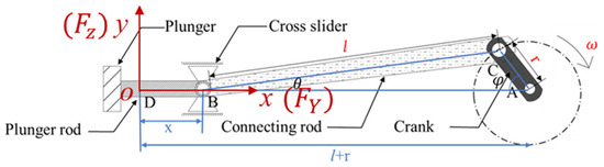
Figure 2.
Diagram of movement of plunger pump crank linkage mechanism.
During the working process of the plunger pump, the displacement of the plunger can be transformed into the displacement of the cross slider, because the trajectories of the plunger and the cross slider are always synchronized and consistent. Taking the left dead center D of the crosshead movement as the origin of the coordinates and taking B to A as the positive direction of the y-axis, the displacement x of the crosshead can be expressed as the following:
where r is length of the crank AC, l is the length of the connecting rod BC, φ is the turning angle of the crank, and θ is the angle between the connecting rod and the axis of the plunger rod. Based on the geometrical relationships in the crank linkage mechanism, the following is obtained:
where λ is the connecting rod ratio, i.e., . Substituting Equation (3) into (1) gives Equation (4).
Further deriving the displacement x from Equation (4), the plunger moves with the velocity u as follows:
where is the angular velocity of the crank’s rotation, and clockwise is positive. Usually, the value of λ is very small, so it can be approximated as , and thus the plunger movement speed u can be expressed as follows:
Deriving the velocity u of the plunger motion from Equation (6), the acceleration a of the plunger motion can be expressed as
According to the plunger motion acceleration a shown in Equation (7), the reciprocating inertia force Fs and centrifugal inertia force Fc generated during the plunger’s motion can be deduced, as shown in Equations (8) and (9), respectively:
where is the mass of the plunger, is the equivalent mass of the crank at point C, is the equivalent mass of the connecting rod at point C, and is the equivalent mass of the connecting rod at point B. Its specific parameters in this study are shown in Table 2.
Table 2.
Main parameters of plunger pump.
According to the arrangement of the plunger pump on the platform (shown in Figure 1b) and its working mechanism, it can be seen that the excitation force of the plunger pump is mainly enacted in the direction of the piston’s movement (i.e., the Y direction) and the direction of the vertical deck (i.e., the Z direction). Since the piston pump is a three-cylinder piston pump, there is a 120° phase difference between the two cylindrical forces, and the time course of the excitation force of the piston pump is shown in Figure 3. In order to facilitate the calculation, the piston pump is established as a rigid body, and the excitation force in the Y and Z directions, as shown in Figure 3, is applied to the piston pump, respectively.
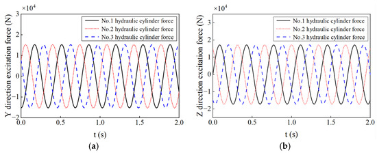
Figure 3.
Excitation force of the plunger pump. (a) Y direction excitation force of the plunger pump; (b) Z direction excitation force of the plunger pump.
We decompose and along the x-axis and y-axis. The x-axis and y-axis in Figure 2 correspond to the Y direction and Z direction in Figure 1, respectively.
The force in the Y direction is
The force in the Z direction is
2.3. Constrained Damping Base Structure and Energy Dissipation Mechanism
In engineering, a support structure is usually installed between the plunger pump and the supporting deck to facilitate lifting and commissioning the plunger pump structure and its ancillary equipment as a whole. Compared with the deck structure, the support skid structure has a lower stiffness, so it will deform somewhat under the action of the plunger pump, which facilitates energy dissipation in the damping material. In this paper, according to the deformation characteristics of the support skid structure, specific thicknesses of the damping material and constraint material are set on both sides of the web of the support skid’s I-beam, which, together with the support skid, forms a constrained damping base structure, as shown in Figure 4. The base dimensions are shown in Figure 5. The vibration damping base contains an I-beam with a high stiffness, a strong restraining layer, and a viscoelastic damping layer.
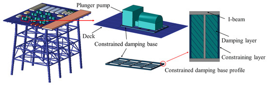
Figure 4.
Constrained damping base layout.
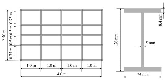
Figure 5.
Constrained damping base dimensions.
In the constrained damping base, the damping layer is made of a viscoelastic polymer, which has both the energy dissipation characteristics of a viscous material and the energy storage characteristics of an elastic material under alternating loads. For the restrained damping base, when the I-beam vibrates under cyclic loading, the damping layer will experience shear deformation along with the vibration of the I-beam, generating dynamic stress or strain. At this stage, some of the energy is converted into heat and dissipates, while the rest is stored in the form of potential energy. In other words, the constrained damping base transforms the mechanical energy of the vibrations into other forms of energy according to the energy dissipation characteristics of the damping material, thus weakening them.
When damping a plunger pump with a constrained damping base, if the excitation frequency of the plunger pump is , the shear strain and the shear stress in the damping layer can be expressed as [28,29]
where is the shear strain amplitude, is the shear stress amplitude, and is the phase angle between the shear stress and the shear strain. Further expansion of Equation (13) yields the following expression:
where is the energy storage’s shear modulus, and , is the energy dissipation’s shear modulus, and .
The phase angle between the shear stress and the shear strain can be obtained from Equation (14) as
where is the loss factor of the viscoelastic damping material, and .
Transforming Equation (14) yields the intrinsic relationship between the stress and strain, as shown in Figure 6. This curve represents the energy dissipation of the viscoelastic material during dynamic loading. Within each cycle of loading, the area enclosed by the curve signifies the energy consumed by the material. This energy dissipation predominantly arises due to internal molecular friction and microstructural changes within the material. The size and shape of the hysteresis loop directly influence the magnitude and rate of this energy dissipation, thereby impacting the material’s vibration damping characteristics. Generally, a larger hysteresis loop corresponds to greater energy dissipation and, consequently, the improved vibration damping properties of the material.
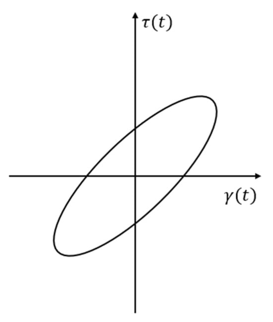
Figure 6.
Stress–strain curve.
As ascertained using Equation (17), the main factors affecting the overall energy dissipation of the constrained damped base are the damping layer’s material loss factor and the damping layer’s shear area. Equally, the damping layer’s shear area is closely related to the thickness of the damping layer and the number of expansion layers. Therefore, this paper investigates the influence of the damping layer’s material loss factor, the thickness of the damping layer, and the number of expansion layers on the vibration isolation performance of constrained vibration damping bases. The parameters corresponding to a more performant vibration isolation base are also determined based on their level of influence. Please refer to the relevant literature for further detail on the parameter selection [28]. The material used in the damping layer of the constrained damping base proposed in this paper is consistent with the literature [29], and its relevant parameters are shown in Table 3.
Table 3.
Material parameters of constrained damping base.
3. Modal Analysis and Vibration Isolation Performance of Constrained Damping Bases
3.1. Modal Analysis of a Constrained Damped Base
Structural modal analysis is an important basis for initially determining the adequacy of a base structure’s design [30,31]. In order to avoid resonance between the vibration isolation base and the excitation load, according to the “Shipboard Vibration Control Guidelines” [32] of the China Classification Society (CCS), the separation margin between the natural frequency fn of the base and the multiple of the excitation frequency f of the plunger pump (mainly its natural frequency and double frequency) should be more than 20%. By this, we mean that when f/fn and 2f/fn are less than 0.8 or more than 1.2, the design of the vibration isolation base is assumed to be reasonable. In this paper, Abaqus software is used to establish numerical models of a rigid base (i.e., a support sled) and a constrained damped base, and modal analysis is carried out. The first four orders of the vibration patterns and the natural frequency are shown in Figure 7 and Table 4.
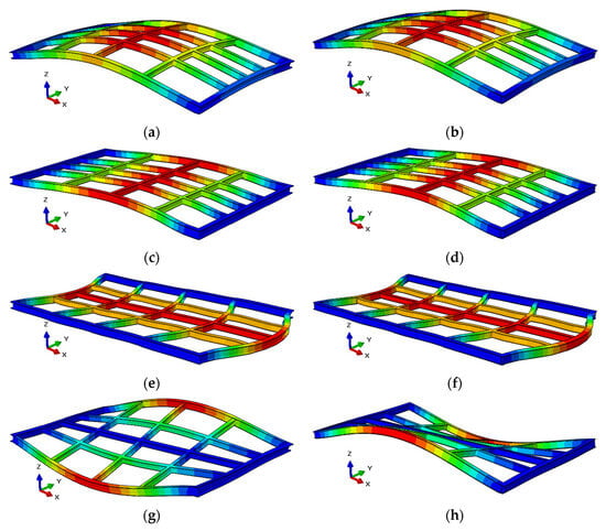
Figure 7.
First four orders of the mode shape for rigid and constrained damping bases. (a) First-order mode shape of the rigid base. (b) First-order mode shape of the constrained damping base. (c) Second-order mode shape of the rigid base. (d) Second-order mode shape of the constrained damping base. (e) Third-order mode shape of the rigid base. (f) Third-order mode shape of the constrained damping base. (g) Fourth-order mode shape of the rigid base. (h) Fourth-order mode shape of the constrained damping base.
Table 4.
The first four orders of natural frequency for bases.
From Figure 7 and Table 4, it can be seen that the first four orders of the vibration mode shape and the natural frequencies of the rigid base and the constrained damped base are close to each other, and the first four orders of the vibration mode shape of both change from bending deformation to torsion deformation. The natural frequency range of the first four orders is about 24~49 Hz, and the frequency ratios f/fn and 2f/fn are in the ranges of (0.060, 0.122) and (0.119, 0.243). The natural frequencies of the rigid base and the constrained damping base do not correspond to any resonance. Therefore, the rigid base and the constrained damped base structures are reasonably designed. The first 10 natural frequencies are shown in Table 5. The first 10 natural frequencies are between 0.63 and 6.07 Hz, while the frequency of the excitation force of the three-cylinder plunger pumps is 8.76 Hz. Therefore, there will be no resonance between the excitation force and the overall model.
Table 5.
The first 10 orders of natural frequency for the platform.
3.2. Vibration Isolation Performance of the Constrained Damping Base
In order to investigate the vibration isolation performance of the constrained damping base, this paper analyzes the vibration response of a polymer injection platform using a rigid base without vibration damping, a traditional rubber vibration isolation base, and the constrained damping base under the conditions of 11 plunger pumps simultaneously operating. In order to show the vibration response characteristics of the deck of the polymer injection platform more clearly, seven measurement points are set up in different areas of the deck, as shown in Figure 1b. The and acceleration levels of each measurement point can be obtained using Equations (18) and (19) to effectively evaluate the vibration response of the polymer injection platform.
where is the root mean square of the vibration velocity (mm/s), T is the duration of the vibration response at the measurement point (s), v(t) is the vibration velocity (mm/s), La is the vibration acceleration level (dB), and ae is the effective value of acceleration (m/s2). The effective value of acceleration is a physical quantity that describes the change in speed of an object in units of time, and its magnitude is equal to the ratio of the area enclosed by the acceleration time–history curve to time.
This paper studied five different grid size configurations using a constrained damping base and compared the of measurement point 1, as shown in Table 6. It can be clearly seen that as the number of grids increases, the of measurement point 1 gradually decreases and stabilizes at 7.8 mm/s. Therefore, it can be concluded that, when the number of grids is 5433, finite element calculation can ensure the calculation’s accuracy, save computational resources, and improve the computational efficiency.
Table 6.
of measurement point 1 under different grid sizes.
A schematic diagram of the conventional rubber vibration isolation base is shown in Figure 8, where six rubber vibration isolators are placed below the base of the rigid base. The size of the rubber isolator is 200 mm × 200 mm × 200 mm. In terms of the material parameters, its density is 100 kg/m3, its elastic modulus is 100 Mpa, and its Poisson’s ratio is 0.3. This paper examines the vibration response of 11 polymer injection pumps operating simultaneously, as shown in Figure 1. In Abaqus software, the plunger pump in Figure 4 is rigidly coupled with the reference point, and excitation forces, as shown in Figure 3, are applied in the Y and Z directions at the 11 reference points. The vibration responses of the platform at different measurement points under the conditions of a rigid base, a conventional rubber vibration isolation base, and only considering the constrained damping base are shown in Figure 9. As can be seen in the figure, the vibration response at measurement points 5, 6, and 7 is smaller compared to the other measurement points due to their distance from the plunger pump. When the platform base is a rigid base, the localized vibration response of the platform deck is intense, and the vibration intensities at measurement points 1, 2, 3, and 4 all exceed the 8 mm/s specified in international standard [33]. When using the traditional rubber vibration isolation base and the constrained damping base, the vibration response at each measurement point is greatly attenuated, and the is less than 8 mm/s, which meets the specification requirements. Comparing the platform’s response under the conditions of the rubber vibration isolator and the constrained damping base, it can be seen that the degree of attenuation of the and the vibration acceleration level at different measurement points differ somewhat, but the differences are small. The vibration acceleration level at measurement point 1 is reduced by 60.67 dB when using the constrained damping base, and it is reduced by 58.00 dB when using a traditional rubber vibration isolation base, which shows that the constrained damped base isolates vibrations more competently than the traditional rubber vibration isolation base.
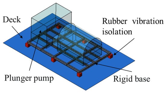
Figure 8.
Conventional rubber vibration isolation base.

Figure 9.
Vibration isolation performance of constrained damping base. (a) Comparison of root mean square value of velocity; (b) comparison of vibration acceleration level.
4. Effect of Damping Layer Parameters on Vibration Isolation Performance
4.1. Effect of the Loss Factor on Vibration Isolation Performance
According to the principles of reducing vibrations using a constrained damping base, we understand that the energy dissipation per unit of volume of the base structure is positively correlated with the loss factor of the damping layer’s material. Therefore, the loss factor of the damping layer’s material is one important index affecting the vibration isolation performance of the constrained damping base. The loss factor of the viscoelastic damping material used is mainly distributed in the range of 0.2~2.0 [34]. In order to explore the nature of the influence of the loss factor of the damping material on the vibration isolation performance of the constrained damping base, this paper sets the energy dissipation factor of the damping material to 0.25, 0.5, 1.0, and 1.5, i.e., 0.5, 1, 2, and 3 times the baseline parameter of the loss factor of the damping material, as described in Table 3, and analyzes the vibration isolation performance of the base. In view of the fact that measurement point 1 is located between several plunger pumps, the vibration response at this measurement point is representative, and the and the vibration acceleration level at measurement point 1 are used below to show the vibration response of the polymer injection platform under different working conditions.
Figure 10 shows a comparison of the results on the and the vibration acceleration level at measurement point 1 using different damping material loss factors. From the figure, it can be seen that the vibration response of the polymer injection platform gradually decreases with an increase in the damping material’s loss factor, but this effect also gradually de-intensifies with an increase in the damping material’s loss factor. Taking the of the platform as an example, when the damping material’s loss factor is increased from 0.25 to 1.0, the of the platform is reduced from 8.06 mm/s to 6.90 mm/s, while when the damping material’s loss factor is increased from 1.0 to 1.5, the of the platform is reduced from 6.90 mm/s to 6.62 mm/s. It is found that when the damping material’s loss factor exceeds 1.0, the decline in the platform’s gradually slows down. That is, the vibration isolation performance of the base gradually tends to stabilize. Considering the cost of the materials and the vibration damping performance, the damping material’s loss factor can be set to 1.0.
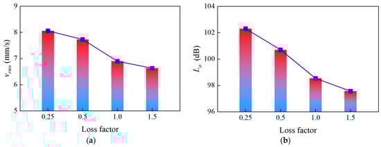
Figure 10.
Effect of loss factor on vibration isolation performance; (a) root mean square value of velocity; (b) vibration acceleration level. (The thickness of the damping layer is 30 mm, the number of expansion layers is 0, and the loss factor is 0.25–1.5. Measurement point 1).
4.2. Effect of the Damping Layer’s Thickness on the Vibration Isolation Performance
According to the principles of vibration isolation in the constrained damped base, the total energy dissipation and the total energy storage of the base structure are related to the shear area of the damping layer. Equally, the shear area of the damping layer has a strong correlation with the thickness of the damping layer. Thus, the thickness of the damping layer is an important index affecting the vibration isolation performance of the constrained damped base. In order to investigate the influence of the damping layer’s thickness on the vibration isolation performance of the constrained damping base, this paper sets up six different working conditions at 5 mm intervals, as shown in Figure 11.

Figure 11.
Constrained damping base with damping layers of different thicknesses.
The platform’s vibration response is shown in Figure 12. From the figure, it can be seen that, with an increase in the thickness of the damping layer, the shear area of the damping layer gradually increases, the vibration response of the platform gradually decreases, and the vibration isolation performance of the constrained damping base continues to improve. Taking the vibration acceleration level of the platform as an example, when the thickness of the damping layer is increased from 5 mm to 20 mm, the acceleration of the vibrations of the platform decreases from 107.70 dB to 102.32 dB, while when the thickness of the damping layer is increased from 20 mm to 30 mm, the acceleration of the vibrations of the platform only decreases from 102.32 dB to 100.70 dB. Furthermore, when the thickness of the damping layer exceeds 20 mm, the decline in the vibration acceleration level of the platform slows down, i.e., the rate of the increase in the vibration isolation performance of the base plateaus. Considering the size of the I-beam and where the restraining plate is installed, the thickness of the damping layer was set to 20 mm in this study.
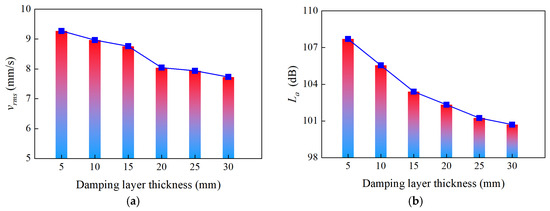
Figure 12.
Effect of damping layer thickness on vibration isolation performance; (a) root mean square value of velocity; (b) vibration acceleration level (the loss factor is 0.25, the number of expansion layers is 0, and the thickness of the damping layer is 5–30 mm. Measurement point 1).
4.3. Effect of the Number of Expansion Layers on the Vibration Isolation Performance
The shear area of the damping layer is not only related to the thickness of the damping layer but also to the number of expansion layers. If there is only one layer of damping material (i.e., no expansion layer), only the part of the damping material in contact with the base’s I-beam undergoes shear deformation under the deformation of the base structure, and the damping layer consumes less energy. If an expansion layer is added to the damping layer, the deformation of the base’s I-beam is hierarchically transferred to the damping layer through the connecting plate, resulting in shear deformation where the damping material is in contact with the connecting plate, which can significantly increase how much structural vibration energy is consumed. In order to investigate the influence of the number of expansion layers on the vibration isolation performance of the constrained damping base, this paper uses different numbers of expansion layers between the damping layer and the I-beam. Constrained damping bases with different numbers of expansion layers are shown in Figure 13, and their specific material parameters are shown in Table 7.
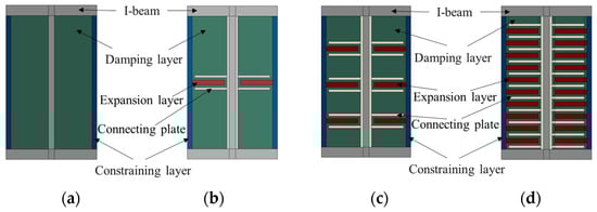
Figure 13.
Constrained damping base with different numbers of expansion layers. (a) Without expansion layer; (b) 1 expansion layer; (c) 3 expansion layers; (d) 10 expansion layers.
Table 7.
Structural parameters of constrained damping base.
The thickness of the connecting plate is 2 mm, the thickness of the expansion layer is 3 mm, and the thickness of the constraining layer is 2 mm. All these data are constant values. This subsection is based on the research in Section 3.2, so the material’s parameters remain the same except for the fact that the number of expansion layers changes; i.e., the loss factor is 0.5, and the rest of the parameters are shown in Table 7. The expansion layer is made of a polyamide material formed with 3D-printed honeycomb pores, which makes it lightweight and highly elastic. The printing temperature is 240 °C, the printing speed is 30 mm/s, the layer height is 0.1 mm, and the accuracy is 0.2 mm. The expansion layer model and its dimensions are shown in Figure 14.

Figure 14.
Expansion layer model.
The and the vibration acceleration level of the platform are shown in Figure 15 for the constrained damping bases with different numbers of expansion layers. A comparison of the results shows that, with an increase in the number of expansion layers, the shear area of the damping layer continues to increase, the vibration response of the platform gradually decreases, and the vibration isolation performance of the constrained damping base gradually improves. The main reason for this is that the shear area of the damping layer increases significantly when the number of expansion layers is increased from 1 to 10, and, due to the bending deformation of the I-beam, the shear effect of the damping layer increases significantly. When the number of expansion layers increases from 0 to 3, the of the measurement point decreases from 7.73 mm/s to 6.65 mm/s, and the vibration acceleration level decreases from 100.70 dB to 97.96 dB. Meanwhile, when the number of expansion layers increases from 3 to 10, the of the measurement point only decreases from 6.65 mm/s to 6.47 mm/s, and the vibration acceleration level only decreases from 97.96 dB to 97.42 dB. The decline in the and vibration acceleration level slows down, and the rate of the increase in the vibration isolation performance of the base stabilizes when more than three expansion layers are used. Given that as the number of expansion layers increases, the base structure becomes more complex and heavier, and it is appropriate to set the number of expansion layers to 3.

Figure 15.
Effect of number of expansion layers on vibration isolation performance. (a) Root mean square value of velocity; (b) vibration acceleration level. (The loss factor is 0.25, the thickness of the damping layer is 30 mm, and the number of expansion layers is 0–10. Measurement point 1).
4.4. Vibration Isolation Performance of the Base after Parameter Optimization
According to the above study, when the loss factor of the damping layer material in the constrained damping base is 1.0, the thickness of the damping layer is 20 mm, and when the number of expansion layers is 3, the base has improved vibration isolation performance. In order to investigate the vibration isolation performance of the constrained damped base after parameter optimization, a model of the base is established, as shown in Figure 16. Figure 17 shows the vibration acceleration–time history for measurement point 1 on the optimized base. The vibration response of the platform before and after the optimization of the base parameters is obtained using numerical methods, and the results are shown in Figure 18. Comparison of the results shows that, compared to the platform’s vibration response when using the base before its optimization, this optimization further reduces the platform vibrations. The vibration acceleration level at measurement point 1 is reduced by 75.25 dB when using the optimized base, effectively improving the vibration isolation performance of the constrained damping base.
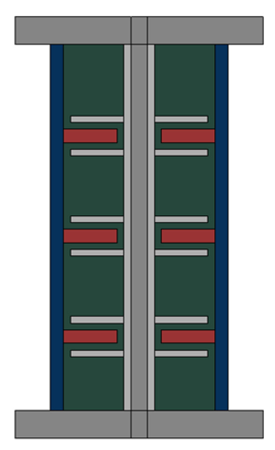
Figure 16.
Constrained damping base with optimized parameters.
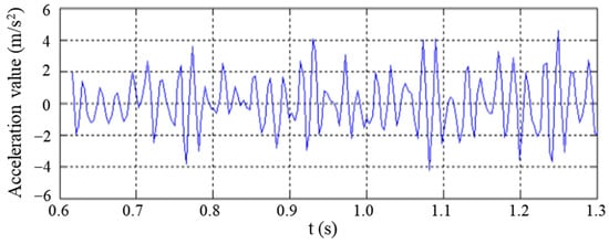
Figure 17.
Time history of vibration acceleration at measurement point 1.
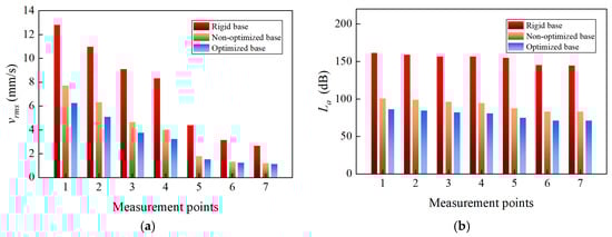
Figure 18.
Vibration isolation performance of constrained damping base with optimized parameters. (a) Comparison of root mean square value of velocity; (b) comparison of vibration acceleration level.
Excessive vibration can cause damage to the human body, including the nervous, cardiovascular, muscular, digestive, bone, and auditory systems. Currently, the level of vibration is typically measured using the vibration acceleration level La in the international community [35]. According to the international standard [36], the vibration acceleration level that the human body can just perceive is 60 dB, and the vibration acceleration level that the human body cannot tolerate is 114 dB. When using an optimized base, the vibration acceleration levels at measuring points 1–7 range from 71 dB to 86 dB, which can be perceived by workers and are within an acceptable range. Therefore, the optimized constrained damping base proposed in this paper meets the health needs of workers.
5. Conclusions
In order to mitigate the local vibrations on offshore platforms caused by the joint operation of multiple plunger pumps, a new constrained damping base was proposed based on the energy dissipation brought about by damped shear deformation. The influence of the loss factor of the damping layer’s material, the damping layer’s thickness, and the number of expansion layers on the vibration isolation performance of the constrained damping base was analyzed. The ideal structural form of the constrained damping base for optimized vibration-reduction performance was determined, and the following conclusions were obtained.
- (1)
- The natural frequency of the first four orders of the constrained damping base proposed in this paper ranged from 24.1 Hz to 42.5 Hz, while the frequency ratios f/fn and 2f/fn were small and were not within the resonance region, so the constrained damping base structure was reasonably designed.
- (2)
- The constrained damping base can effectively reduce the vibration response on the platform deck elicited by the plunger pumps, and the base evidently isolates vibrations effectively, given that its vibration acceleration level at measurement point 1 is reduced by 60.67 dB.
- (3)
- The isolation performance of the constrained damping base was superior to that of rigid bases and rubber bases. Compared with traditional rubber isolation bases, constrained damping bases have the advantages of simple construction, a low center of gravity, and more stable operation.
- (4)
- With a gradual increase in the damping material’s loss factor, the vibration isolation performance of the constrained damping base continuously improves. An increase in the thickness of the damping layer and an increase in the number of expansion layers continuously enlarges the shear area of the damping layer, which, in turn, continuously improves the performance of the constrained damping base in isolating the vibrations. When the damping material’s loss factor is 1.0, the thickness of the damping layer is 20 mm, and the number of expansion layers is 3, the vibration isolation performance of the constrained damping base is enhanced, and the vibration acceleration level at measurement point 1 is reduced by 75.25 dB.
Author Contributions
Conceptualization, Z.Z. and S.W.; methodology, Z.Z., S.W. and X.W.; software, Z.Z. and X.W.; validation, X.S.; formal analysis, Z.Z.; investigation, Z.Z. and X.W.; resources, Z.Z. and S.W.; data curation, Z.Z.; writing—original draft preparation, X.S.; writing—review and editing, Z.Z., X.S. and X.W.; visualization, Z.Z. and X.W.; supervision, S.W.; project administration, X.S.; funding acquisition, S.W. All authors have read and agreed to the published version of the manuscript.
Funding
The support from the National Science Foundation of China (52088102) and the Major Scientific and Technological Innovation Project of Shandong Province (2019JZZY010820) is greatly appreciated.
Institutional Review Board Statement
Not applicable.
Informed Consent Statement
Not applicable.
Data Availability Statement
All the data are presented in the paper.
Conflicts of Interest
The authors declare no conflicts of interest.
References
- Zhang, W.S.; Li, D. Active control of axial dynamic response of deepwater risers with linear quadratic gaussian controllers. Ocean Eng. 2015, 109, 320–329. [Google Scholar] [CrossRef]
- Rabiee, A.H.; Rafieian, F.; Mosavi, A. Active vibration control of tandem square cylinders for three different phenomena: Vortex-induced vibration, galloping, and wake-induced vibration. Alex. Eng. J. 2022, 61, 12019–12037. [Google Scholar] [CrossRef]
- Sarrafan, A.; Zareh, S.H.; Khayyat, A. Neuro-fuzzy control strategy for an offshore steel jacket platform subjected to wave-induced forces using magnetorheological dampers. J. Mech. Sci. Technol. 2012, 26, 1179–1196. [Google Scholar] [CrossRef]
- Nazokkar, A.; Dezvareh, R. Vibration control of floating offshore wind turbine using semi-active liquid column gas damper. Ocean Eng. 2022, 265, 112574. [Google Scholar] [CrossRef]
- Xu, Y.H.; Wang, S.Q.; Zhang, Y.; Zheng, Z.Z. Research on the performance of quasi-zero-stiffness vibration isolator based on ABAQUS multi-body analysis. Period. Ocean Univ. China 2022, 52, 130–137. [Google Scholar]
- Moharrami, M.; Tootkaboni, M. Reducing response of offshore platforms to wave loads using hydrodynamic buoyant mass dampers. Eng. Struct. 2014, 81, 162–174. [Google Scholar] [CrossRef]
- Jin, Z.; He, L.; Zhao, Y.L. Fatigue life prediction of rubber isolator based on force-controlled temperature-accelerated fatigue experiment. J. Fail. Anal. Prev. 2017, 17, 774–779. [Google Scholar] [CrossRef]
- Rahnavard, R.; Thomas, R.J. Numerical evaluation of steel-rubber isolator with single and multiple rubber cores. Eng. Struct. 2019, 198, 109532. [Google Scholar] [CrossRef]
- Rahnavard, R.; Craveiro, H.D.; Napolitano, R. Static and dynamic stability analysis of a steel-rubber isolator with rubber cores. In Structures; Elsevier: Amsterdam, The Netherlands, 2020; Volume 26, pp. 441–455. [Google Scholar]
- Roncen, T.; Sinou, J.; Lambelin, J.P. Experiments and nonlinear simulations of a rubber isolator subjected to harmonic and random vibrations. J. Sound Vib. 2019, 451, 71–83. [Google Scholar] [CrossRef]
- Wang, H.; Cao, S.; Luo, X.; He, X.; Zhang, Z.; Zhu, Y. Study on the influence of rubber isolator’s dynamic stiffness on the dynamic behavior of seawater hydraulic piston pump. Ocean Eng. 2019, 182, 14–20. [Google Scholar] [CrossRef]
- Kerwin, E.M. Damping of flexural waves by a constrained viscoelastic layer. J. Acoust. Soc. Am. 1959, 31, 952–962. [Google Scholar] [CrossRef]
- Wei, P.B.; Xia, H.; Cao, Y.M.; Zhan, J.W. Experimental study on vibration reduction of rail with compound damping board. J. Beijing Jiaotong Univ. 2007, 31, 35–39. [Google Scholar]
- Zeng, Q.E.; Liu, L.Y.; Yin, X.J. Experimental research on noise reduction performance of damping rails. Tech. Acoust. 2012, 31, 98–101. [Google Scholar]
- Li, J.Y.; Liu, L.Y.; Yin, X.J. Experimental study on noise and vibration reduction of labyrinth constrained damped rail. J. East China Jiaotong Univ. 2016, 33, 31–36. [Google Scholar]
- Zhang, X.M.; Zhou, H.Y.; Yao, G.L.; Liu, D.Y.; Yin, X.J.; Zhao, C.Y. Experimental study on noise-reducing characteristics of broadband labyrinth constrained damping rail. Railw. Eng. 2020, 60, 137–142. [Google Scholar]
- Levraea, V.; Rogers, L.; Parin, M.; Pacia, A. Add-On Damping Treatment for Life Extension of the F-15 Upper-Outer Wing Skin: WL-TM-91-307-FIBG; Wright Patterson AFB OH; US Wright Laboratory: Dayton, OH, USA, 1991. [Google Scholar]
- Gu, S.K.; Deng, Q.; Liu, Y. Study on mechanical properties and parameter optimization of constrained damping structures. Adv. Aeronaut. Sci. Eng. 2021, 12, 68–89. [Google Scholar]
- Kouritem, S.A.; Elshabasy, M.M.Y.B. Tailoring the panel inertial and elastic forces for the flutter and stability characteristics enhancement using copper patches. Compos. Struct. 2021, 274, 114311. [Google Scholar] [CrossRef]
- Elshabasy, M.M.Y.B.; Kouritem, S.A. Thickening of optimally selected locations on panels subjected to unyawed flow for substantial delay of the panel flutter. Alex. Eng. J. 2020, 59, 5031–5044. [Google Scholar] [CrossRef]
- Shaukat, H.; Ali, A.; Ali, S.; Altabey, W.A.; Noori, M.; Kouritem, S.A. Applications of Sustainable Hybrid Energy Harvesting: A Review. J. Low Power Electron. Appl. 2023, 13, 62. [Google Scholar] [CrossRef]
- Hassan, E.; Kouritem, S.A.; Amer, F.Z.; Mubarak, R.I. Acoustic energy harvesting using an array of piezoelectric cantilever plates for railways and highways environmental noise. Ain Shams Eng. J. 2024, 15, 102461. [Google Scholar] [CrossRef]
- Shaukat, H.; Ali, A.; Bibi, S.; Altabey, W.A.; Noori, M.; Kouritem, S.A. A Review of the recent advances in piezoelectric materials, energy harvester structures, and their applications in analytical chemistry. Appl. Sci. 2023, 13, 1300. [Google Scholar] [CrossRef]
- Wang, M.; Zhang, W.Q.; Wang, P.G.; Du, X.L. Multiple hazards vibration control of jacket offshore wind turbines equipped with amplifying damping transfer systems: Winds, waves, and earthquakes. Ocean Eng. 2023, 285, 115355. [Google Scholar] [CrossRef]
- Xia, Z.; Kai, J.; Wang, X.; Shao, G.; Jiang, W.; Sun, Y. Study on semi-active particle damping technology for offshore platform truss structure. J. Vibroeng. 2016, 18, 4248–4260. [Google Scholar] [CrossRef][Green Version]
- Ou, J.; Long, X.; Li, Q.S.; Xiao, Y.Q. Vibration control of steel jacket offshore platform structures with damping isolation systems. Eng. Struct. 2007, 29, 1525–1538. [Google Scholar] [CrossRef]
- Sun, Y.H.; Niu, Q.; Nie, L.W.; Zhang, J.G. Vibration Control of Offshore Platform Based on Outrigger Damping System. Appl. Mech. Mater. 2013, 351–352, 1112–1116. [Google Scholar] [CrossRef]
- Cui, R.X. Mechanism of Vibration and Noise Reduction of Additional Damping Treatment for Rail in High-Speed Railway and Its Application. Ph.D. Thesis, Beijing Jiaotong University, Beijing, China, 2018. [Google Scholar]
- Zhang, W.P. Research on Material Layout Optimization of Viscoelastic Damping Layer for Constrained Damping Structure. Master’s Thesis, Nanchang Hangkong University, Nanchang, China, 2021. [Google Scholar]
- Bao, X.; Sun, H.; Iglesias, G. Signal denoising method for modal analysis of an offshore platform. J. Loss Prev. Process Ind. 2020, 63, 104000. [Google Scholar] [CrossRef]
- Wang, S.Q.; Liu, F.S.; Zhang, M. Modal strain energy based structural damage localization for offshore platform using simulated and measured data. J. Ocean Univ. China 2014, 13, 397–406. [Google Scholar] [CrossRef]
- China Classification Society. Guide for Vibration Control on Board Ships; China Communication Press: Beijing, China, 2004. [Google Scholar]
- ISO 6954:2000(E); Mechanical Vibration-Guidelines for the Measurement, Reporting and Evaluation of Vibration with Regard to Habitability on Passenger and Merchant Ships. ISO: Geneva, Switzerland, 2000.
- Xu, Y.; Xu, Z.D.; Guo, Y.Q.; Sarwar, W.; She, W.; Geng, Z.F. Study on viscoelastic materials at micro scale pondering supramolecular interaction impacts with DMA tests and fractional derivative modeling. J. Appl. Polym. Sci. 2023, 140, e53660. [Google Scholar] [CrossRef]
- Dong, S.; Zhu, Y. Effects of environmental vibration on man. Noise Vib. Control 2004, 24, 4. [Google Scholar]
- ISO 2631-1:1997; Mechanical Vibration and Shock-Evaluation of Human Exposure to Whole-Body Vibration. ISO: Geneva, Switzerland, 1997.


Disclaimer/Publisher’s Note: The statements, opinions and data contained in all publications are solely those of the individual author(s) and contributor(s) and not of MDPI and/or the editor(s). MDPI and/or the editor(s) disclaim responsibility for any injury to people or property resulting from any ideas, methods, instructions or products referred to in the content. |
© 2024 by the authors. Licensee MDPI, Basel, Switzerland. This article is an open access article distributed under the terms and conditions of the Creative Commons Attribution (CC BY) license (https://creativecommons.org/licenses/by/4.0/).