Article

Enhancing the Stability of Small Rescue Boats: A Study on the Necessity and Impact of Hydraulic Interconnected Suspensions

by
Xiaochun Mu
,
Hongwang Du
*,
Wenchao Wang
and
Wei Xiong
Ship Electromechanical Equipment Institute, Dalian Maritime University, Dalian 116026, China
*
Author to whom correspondence should be addressed.
J. Mar. Sci. Eng. 2024, 12(7), 1074; https://doi.org/10.3390/jmse12071074
Submission received: 7 June 2024 / Revised: 20 June 2024 / Accepted: 22 June 2024 / Published: 26 June 2024
(This article belongs to the Special Issue Advances in the Performance of Ships and Offshore Structures)

Abstract

:
Aiming to solve the problem that existing small rescue boats cannot realize the effective and stable rescue of human lives under high sea turbulence conditions, this paper proposes a parallel decoupled hydraulic interconnected suspension system for actual sea state. The system dynamics model is established, and its damping characteristics are analyzed by joint simulation. The results show that compared with the truss-type rescue ship, the suspension system can improve the transverse rocking resistance by 81.5% and the longitudinal rocking resistance by 25.0%, and the system has excellent transverse rocking resistance.

1. Introduction

Due to its rapid maneuverability, the small-sized catamaran rescue vessel has become an effective tool for saving lives at sea. However, existing small rescue boats still fail to meet the operational requirements in high sea turbulence conditions. Under severe sea conditions, waves can cause multi-degree-of-freedom impact and vibration to the hull, making it difficult for lifesavers to approach and provide effective and stable rescue to those in the water. Equipping rescue boats with vibration reduction suspension is an effective means to address this issue. Hydraulic interconnected suspension technology has significant advantages in improving ride comfort, handling stability, and multi-condition adaptability. By connecting various parts of the system through hydraulic oil, the interconnected suspension forms an integrated unit, which can reduce the vertical and rolling direction transmission amplitude ratio transmitted from the front and rear suspensions to the body, thus enhancing comfort. At the same time, it can provide anti-rolling and anti-pitching torques to improve handling stability. In terms of multi-condition adaptability, the system can achieve multi-degree-of-freedom motion compensation based on different operating conditions.
Marine Advanced Robotics, a US company [1,2,3,4], conducted excitation tests in a laboratory environment using a unilateral wave simulation device for a 33-foot WAM-V (Marine Advanced Robotics, Richmond, CA, USA) prototype. The tests showed that the suspension system had the best compensation effect in longitudinal motion compensation, and improvements to the suspension system could enhance the vessel’s handling stability. Servo Yachts, another US company [5], introduced the Martini series of boats in 2012. The upper hull is hinged to two floating hulls through anti-rolling mechanisms, absorbing rolling, pitching, and heaving motions caused by waves, making them suitable for search and rescue operations in severe sea conditions. Nauti-Craft, an Australian company [6], developed a real-world wave-adaptive high-speed boat using a new hydraulic interconnected suspension system. The active control system adjusts the stroke of each hydraulic cylinder in real time based on the sea waves, providing motion compensation for at least two degrees of freedom among rolling, pitching, heaving, and twisting motions. Professor Daisuke Kitazawa from Tokyo University [7,8] designed and manufactured the WHzer series prototype, conducting tests on ship vibration and energy recovery. The test results showed that the suspension system could significantly compensate for the rolling, pitching, and heaving motions of the ship, with the maximum motion compensation reaching 79.5%.
Improving ride comfort has always been a long-standing issue in the transportation industry. Compared to road contours, the ocean surface is rougher and more prone to causing severe shaking [9]. However, due to the complexity of ocean impacts, suspension systems are rarely used in marine vessels to improve ride comfort and stability [10]. In the automotive industry, Wilde JR [11,12] proposed a passive hydraulic interconnected suspension, which was verified through ADAMS simulation and experimental studies to improve the roll stiffness of the vehicle during high-speed cornering. Smith [13] conducted theoretical analysis and experimental research on the H2 anti-roll interconnected suspension system, revealing that the suspension system significantly increased roll stiffness without affecting vertical stiffness but had complex response characteristics under high-frequency vibrations. Vigliani [14] proposed a new suspension system with a transition cylinder and spring damper. The indirect interconnection of the suspension system achieved the interconnection of the entire vehicle suspension system. The test results showed that this system improved the vehicle’s anti-rolling ability and stability. The impacts caused by complex road conditions on vehicles are mutually coupled and always present. Some scholars have introduced the idea of modal control and conducted relevant research on the motion decoupling of suspension systems. In 2000, Zapletal [15] theoretically proposed a “balanced suspension” that uses hydraulic lines to connect the actuators and control units, enabling the complete decoupling of the suspension motion compensation modes. The independent control of each motion compensation was achieved through hydraulic and mechanical methods. In 2002, Buj [16] proposed a hydraulic interconnected suspension decoupling solution that uses a hydraulic control unit to connect four accumulators with the suspension circuit, determining the stiffness and damping parameters of each motion mode to achieve decoupled motion compensation. Smith [17] and others proposed an ideal new decoupling suspension concept combining network theory and system synthesis ideas. This suspension achieves complete decoupling of stiffness and damping parameters through a central control unit. Mavroudakis [18] and others also proposed a decoupling suspension controlled by a central control unit system and conducted simulation analysis in SIMPACK. The results showed that the decoupling suspension significantly outperformed traditional independent suspension systems. In previous work [19], a hydraulic interconnected suspension system with three-degree-of-freedom wave compensation capabilities was proposed. This suspension system uses multi-section cylinders as transition elements to couple multiple chambers of four hydraulic cylinders to meet the wave adaptation needs of small rescue vessels in terms of rolling, pitching, and heaving. In recent years, scholars from Hunan University have achieved remarkable progress in the research of hydraulically interconnected suspension (HIS) systems. Zhang Nong [20,21] and his colleagues proposed a frequency domain analysis method based on the system. This method utilized the velocity–flow relationship of the double-acting hydraulic cylinder piston rod as the boundary condition for the mechanical–fluid coupling. The dynamic fluid state at the end of a single branch was determined by the transfer matrix, thus establishing a mechanical–fluid coupling model. Eventually, the complete system equations for half of the vehicle were derived, and two universal impedance matrices for double-cylinder interconnection were presented. This model verifies that the HIS system can achieve the independent control of stiffness and damping to a certain extent.
Addressing the challenges of complex coupling, increased difficulty in system control, growing number of intermediate components, and difficulties in theoretical research in interconnected suspension systems, this paper takes the hydraulic interconnected suspension system of small rescue boats as the research object. The main contributions are as follows: (1) a parallel decoupling interconnected suspension system suitable for actual sea conditions is proposed, and the vibration reduction characteristics of the suspension system under different wave impacts are obtained; (2) through hydraulic interconnection experiments, the displacement compensation characteristics of the suspension system are obtained, verifying the superiority and practicability of the parallel interconnected suspension system.
The remaining structure and content of this paper are organized as follows: Section 2 proposes a parallel interconnected suspension system and analyzes its working principle. Section 3 establishes a joint simulation model of the hydraulic interconnected suspension system for small rescue boats and conducts multi-condition simulations of the suspension system. Section 4 builds an interconnected suspension test bench, conducts the experimental verification of the basic interconnection principle, simulates and identifies the basic friction and dynamic friction coefficients of the interconnected suspension, and finally conducts an experimental study on the coupling characteristics of the 1/2 parallel interconnected suspension system.

2. Design of Hydraulic Interconnected Suspension System

This article proposes a parallel decoupled interconnection suspension system for small rescue vessels under high-coupled impact conditions during ocean navigation, as shown in Figure 1. It consists of an anti-pitch interconnection system and an anti-roll interconnection system. In the face of complex wave impacts, the waves acting on the buoy are decoupled and decomposed into combined anti-pitch and anti-roll effects that are applied to the upper hull, thus enabling the small rescue vessel to achieve wave-adaptive vibration reduction capabilities in actual sea conditions.

2.1. Operational Area Analysis and Wave Condition Adaptation for Rescue Boats

The hydraulic interconnected suspension system designed in this paper is used to improve the shock absorption performance of small catamaran rescue boats. The specific mission scenarios are rescue of human lives in offshore and inland waters, as well as the auxiliary rescue work of large rescue vessels in distant areas, especially by maintaining stability and navigation efficiency in the case of large wind and waves.

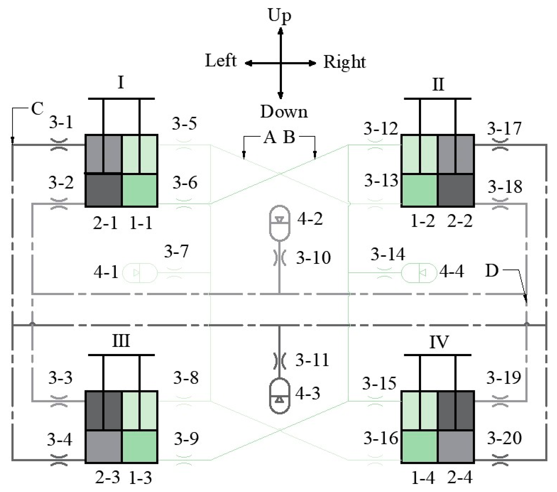
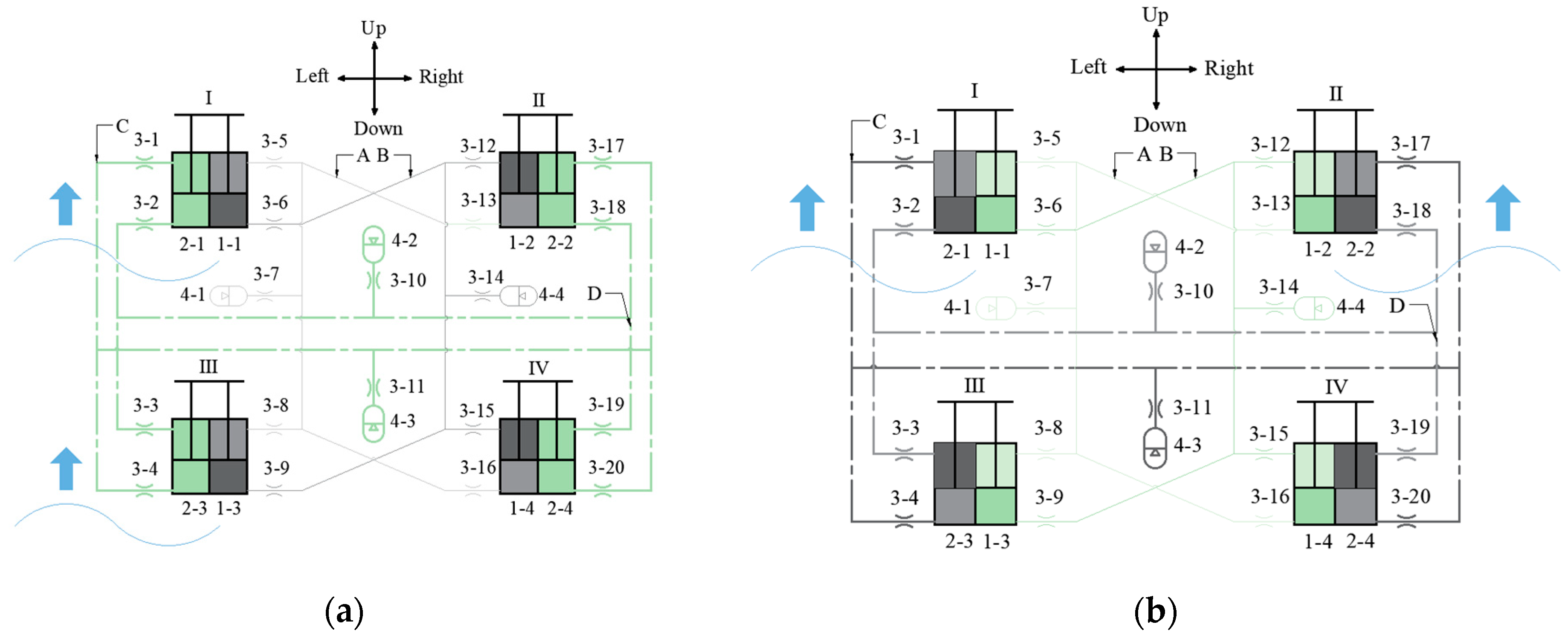
2.2. Analysis of the Working Principle of Suspension System

During the navigation and rescue operations of small rescue vessels, they are usually subjected to the impact of beam waves with wave direction angles ranging from 75° to 105°, head waves with wave direction angles ranging from 165° to 180°, and quartering waves with wave direction angles of 135 ± 30°. When the suspension system is impacted by beam waves, the anti-roll interconnection suspension system becomes active. During this instant, the center of gravity of the upper hull experiences little fluctuation, and the left pontoon tends to move upwards. This causes the piston rods of hydraulic cylinders 1-1 and 1-3 to retract, reducing the volume of the rodless chambers and increasing the pressure. The oil then flows through the anti-roll circuits A and B into the rod chambers of hydraulic cylinders 1-2 and 1-4. At the same time, the oil in the rod chambers of hydraulic cylinders 1-2 and 1-4 flows in, increasing the chamber pressure and pushing the piston rods to retract, resulting in a tendency for the right pontoon to move upwards. Both pontoons on either side have a tendency to move upwards simultaneously, keeping the main hull relatively stable under wave impacts.
When the main hull undergoes a rightward roll, the rodless chambers of hydraulic cylinders 1-2 and 1-4 are compressed, causing the piston rods to move up and increasing the chamber pressure, allowing oil to flow out. Meanwhile, the piston rods of the left hydraulic cylinders 1-1 and 1-3 move down, reducing the pressure in the rodless chambers and allowing oil to flow in. This results in a pressure difference between circuits A and B, creating an upward force and an anti-roll moment, enhancing the vessel’s anti-roll capability. Simultaneously, the anti-pitch circuits C and D also experience oil flow due to wave impacts, but only laterally between the two pontoons. Due to the connection of the circuits, the oil flows back and forth with the up-and-down displacement of the hydraulic cylinders, without any oil flowing into or out of the accumulator. Thus, the pressure in circuits C and D remains unchanged.
Similarly, when the suspension system is impacted by head waves, the anti-pitch interconnection suspension system becomes active. Figure 2a illustrates the working principle of the suspension system under beam wave impacts, while Figure 2b depicts the working principle under head wave impacts.
When a small-sized catamaran rescue boat is subjected to various sea wave impacts, the suspension system can decompose the wave impacts into beam waves and head waves for adaptive wave damping and absorption. Concurrently, the accumulator in the suspension system is capable of absorbing shocks within the system, while the damping valve quickly converges the fluctuations within the system, reducing the vibration of the main hull. This comprehensive approach enhances the ride comfort and seaworthiness of the small rescue boat.

3. Modeling and Simulation of Interconnected Suspension System Dynamics

This paper investigates the loop dynamic characteristics and damping performance of the hydraulically interconnected suspension system. A hydraulic system model is built using AMESim(2016), and a ship dynamics model is developed using ADAMS(2018). During the simulation, the kinematics of the vessel are calculated in ADAMS(2018), while the dynamics of the suspension system are solved in AMESim(2016) and then fed back into ADAMS(2018). Through the combined simulation of AMESim(2016)-ADAMS(2018), the dynamic characteristics of the interconnected suspension system are studied. The combined simulation is primarily achieved by utilizing the “FMU” (Functional Mock-up Unit) command, and the basic combined simulation process is illustrated in Figure 3.

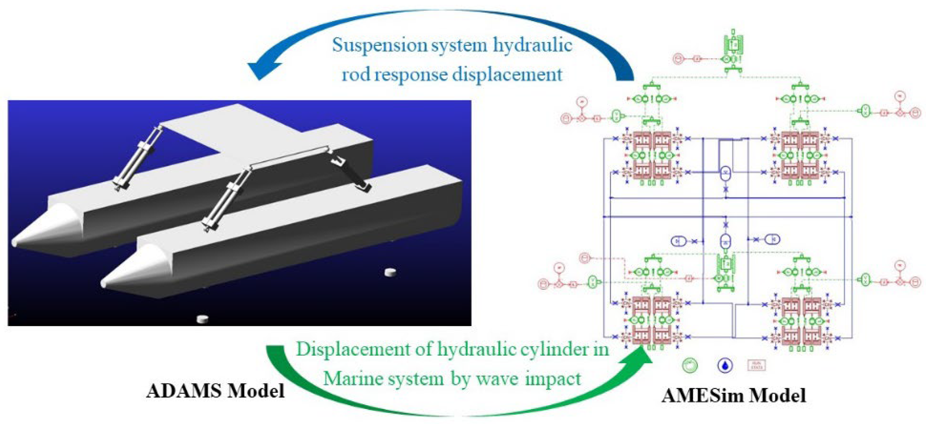
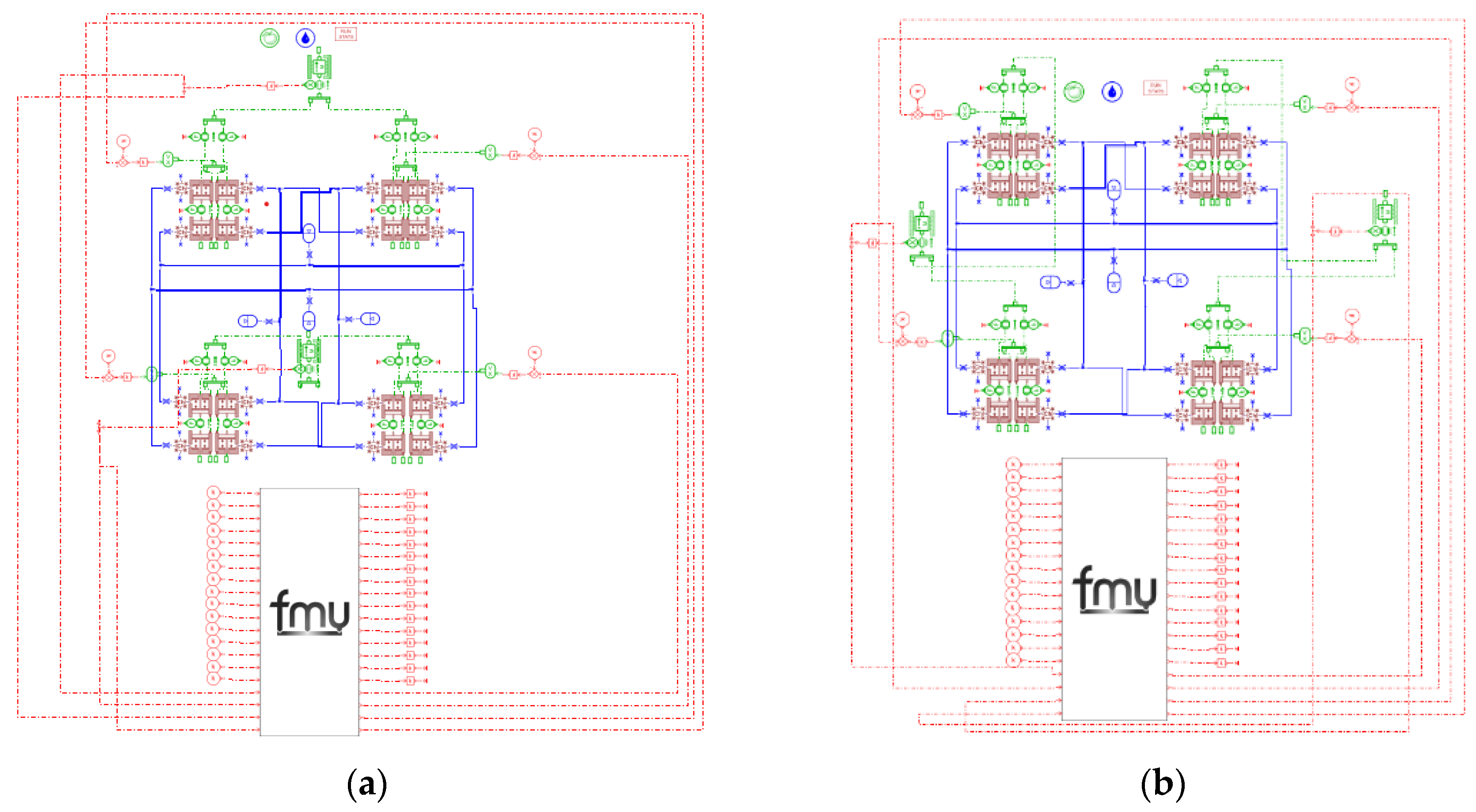
3.1. Joint Simulation Model Modeling

In the AMESim(2016) model, the front and rear suspension mass blocks are used to simulate the suspension response of the ship when it is impacted by head waves. Similarly, the left and right suspension simulation models mimic the suspension response of the ship when it encounters beam waves. In the ADAMS(2018) model, a mass–spring–damper model is employed to roughly realize the impact effect between the ship and the sea waves. The schematic diagram of the established ADAMS(2018)-AMESim(2016) combined simulation model is shown in Figure 4, and the main parameters of the ADAMS model are listed in Table 1
The parallel interconnected suspension system consists of an anti-pitch interconnected suspension and an anti-roll interconnected suspension. Based on the results of the parallel interconnected suspension test, the basic parameters such as the basic friction force and static friction coefficient of the interconnected suspension system are set. The combined simulation models of the parallel interconnected suspension system are shown in Figure 5a,b, and the main parameters of the hydraulically interconnected suspension system are listed in Table 2.

3.2. Multi-Operating Condition Simulation

In the simulation, the wave direction angle of beam waves is considered as a single-cycle sinusoidal signal of 90°, and the wave direction angle of head waves is taken as 180° to mimic the impact of single-peak waves. By applying sinusoidal amplitude excitations of 100, 250, and 400 mm, respectively, the ship’s response characteristics under the impact of beam waves, head waves, and large-amplitude heave are analyzed. The schematic diagrams of wave impact conditions are shown in Figure 6a,b.

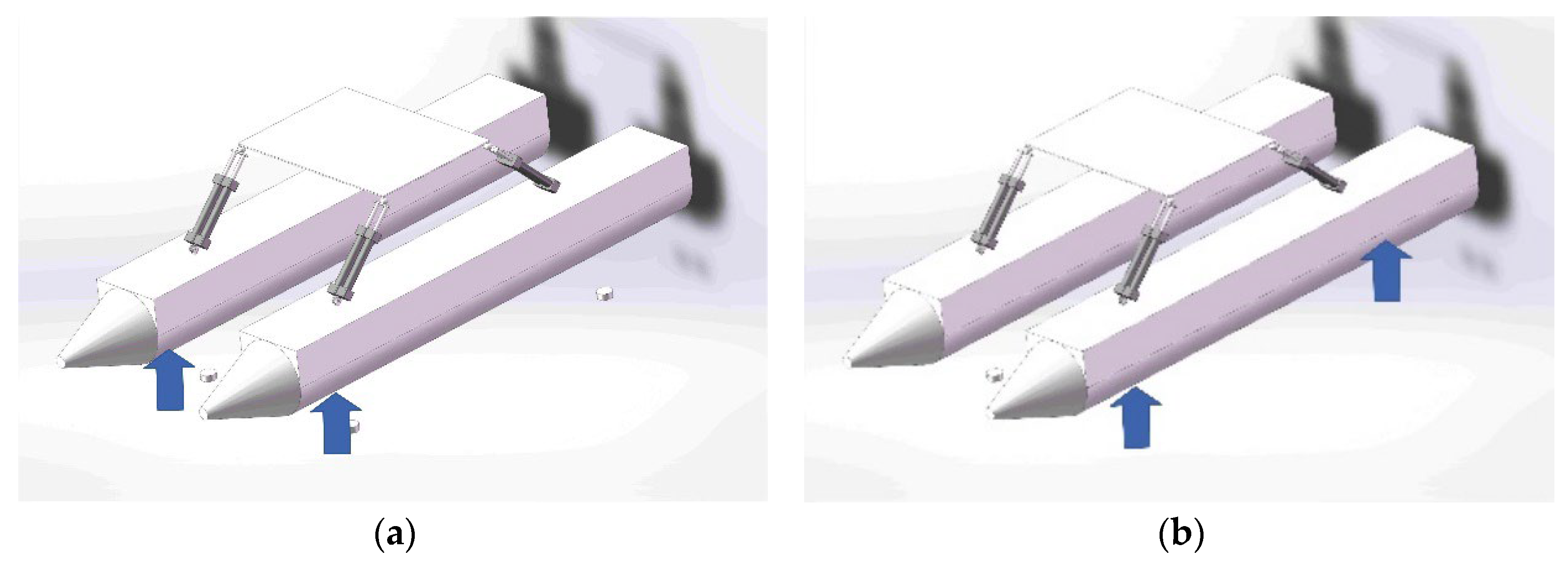
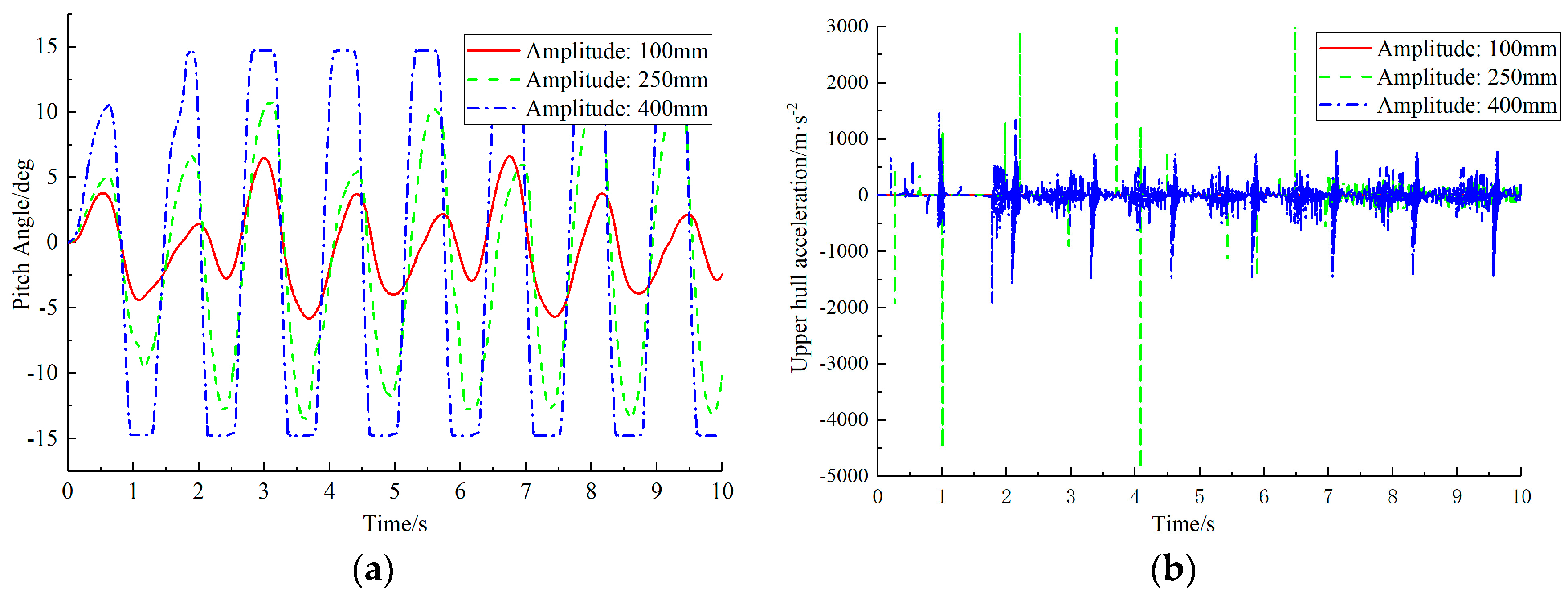
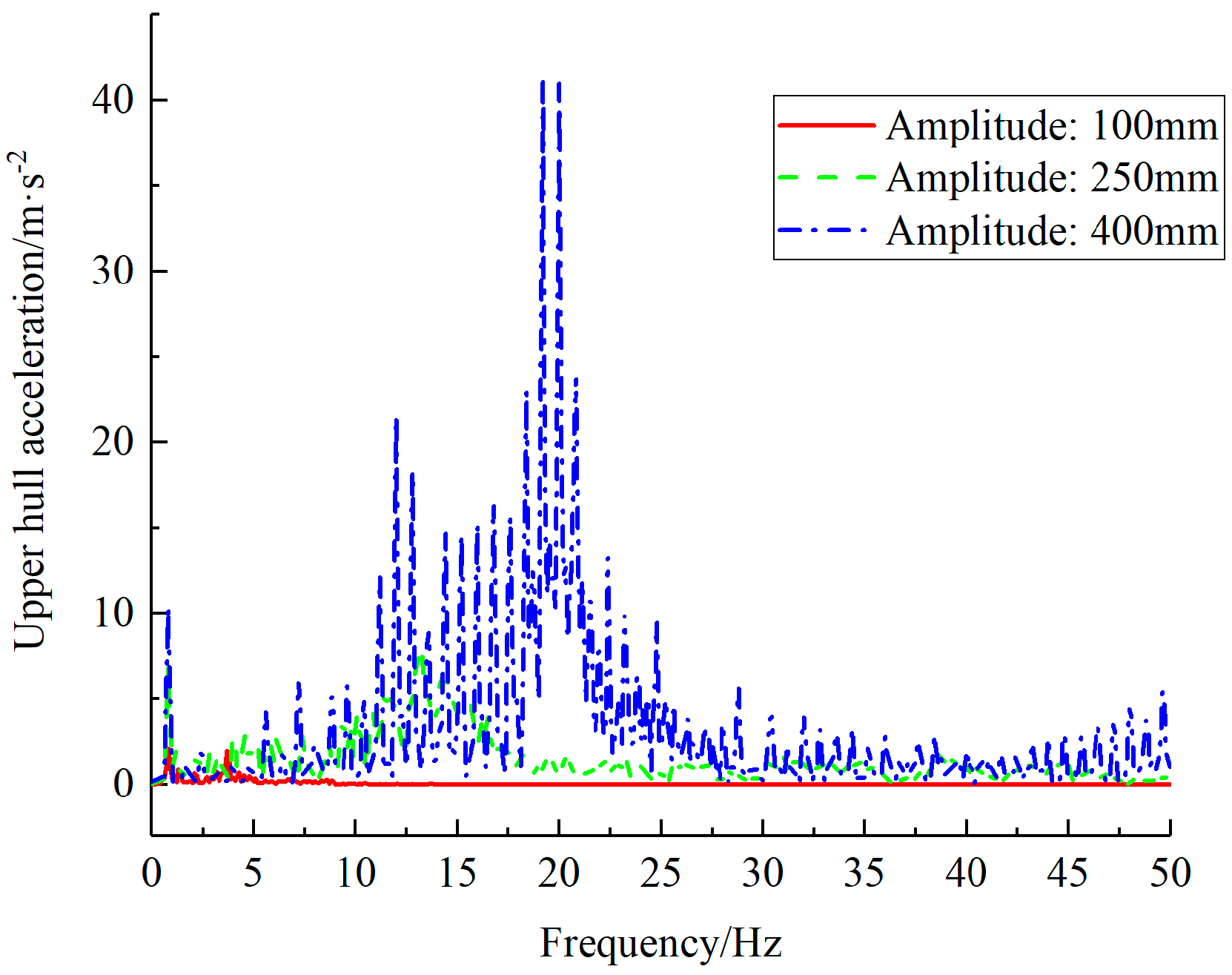
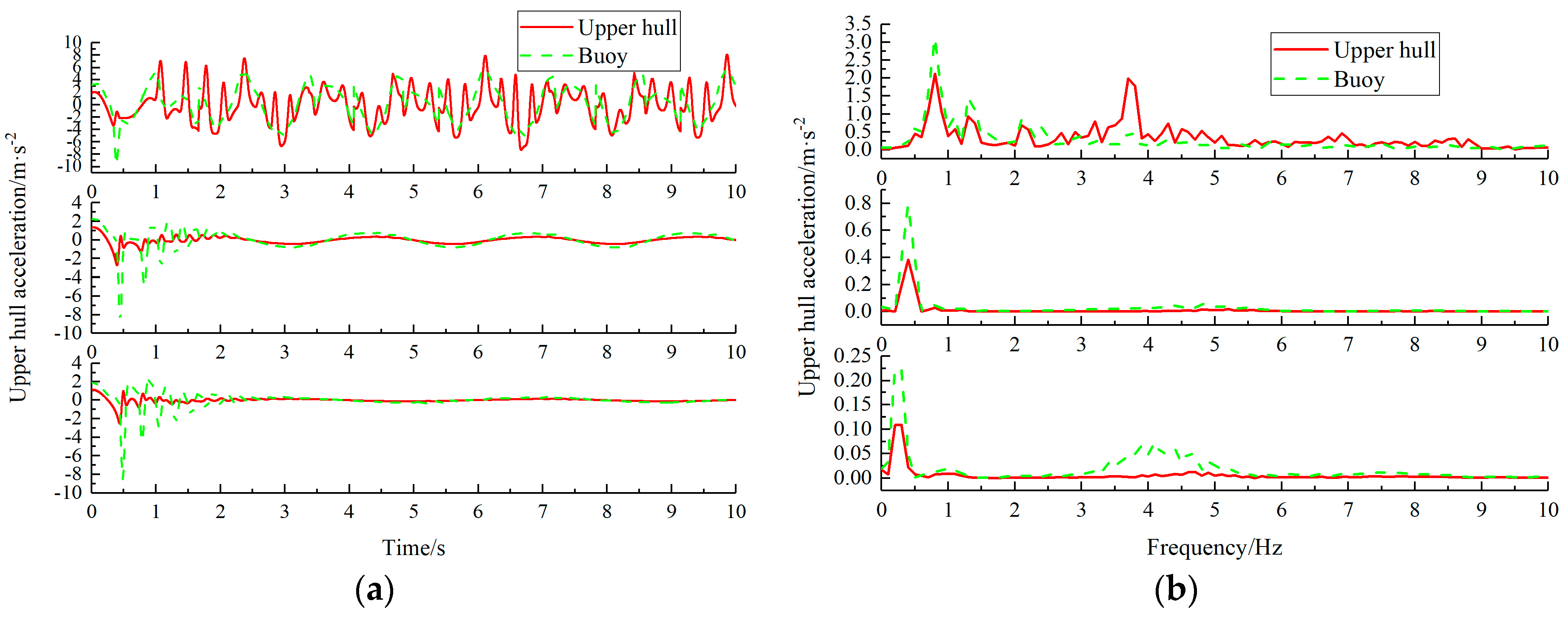
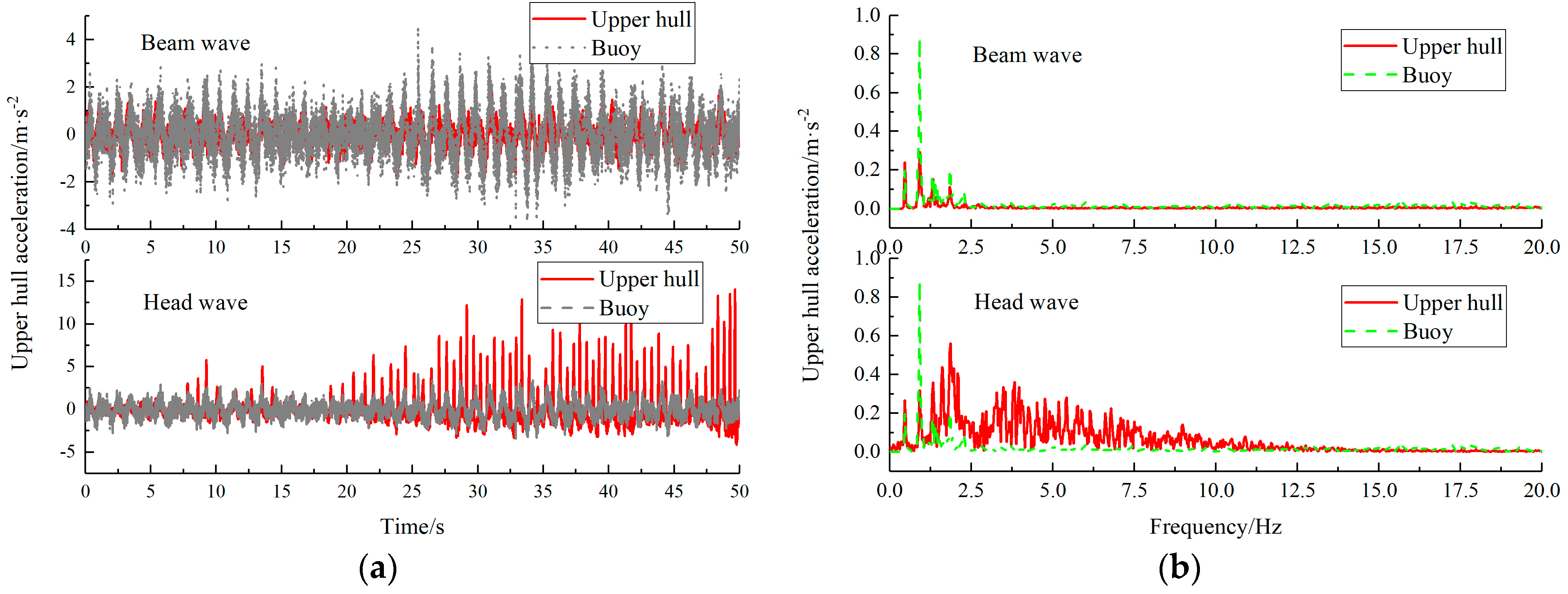
3.2.1. Top Wave Impact

  • Different Wave Grades
Sine wave impacts with amplitudes of 100, 250, and 400 mm and a frequency of 0.8 Hz are set to simulate the working environment of a ship under sea states 1, 2, and 3. Figure 7a shows the pitch angle response curves under impacts with various amplitudes, while Figure 7b and Figure 8 present the acceleration response curves of the upper hull under impacts with different amplitudes.
As can be seen from the figures, when subjected to a large wave excitation of 400 mm, the hydraulic cylinder reaches its motion limit, and the hull motion also reaches its limit. From the roll angle response, it can be observed that the roll angle response amplitudes under impacts with different amplitudes are approximately 5°, 10°, and 15°, respectively. As the excitation amplitude increases, the ship’s pitch motion is more significantly affected by the excitation amplitude. Observing the upper hull acceleration, it is evident that when the excitation amplitude increases, the instantaneous change in hull acceleration is significant, and this phenomenon becomes increasingly severe with the increase in excitation amplitude, with the greatest impact occurring during moderate waves. From the acceleration frequency domain, it can be seen that as the excitation amplitude increases, the vibration amplitude and frequency of the hull also change. Additionally, as the amplitude increases, the main excitation frequency shifts backward, indicating that the suspension system is greatly influenced by head sea impacts and wave grades.
2.
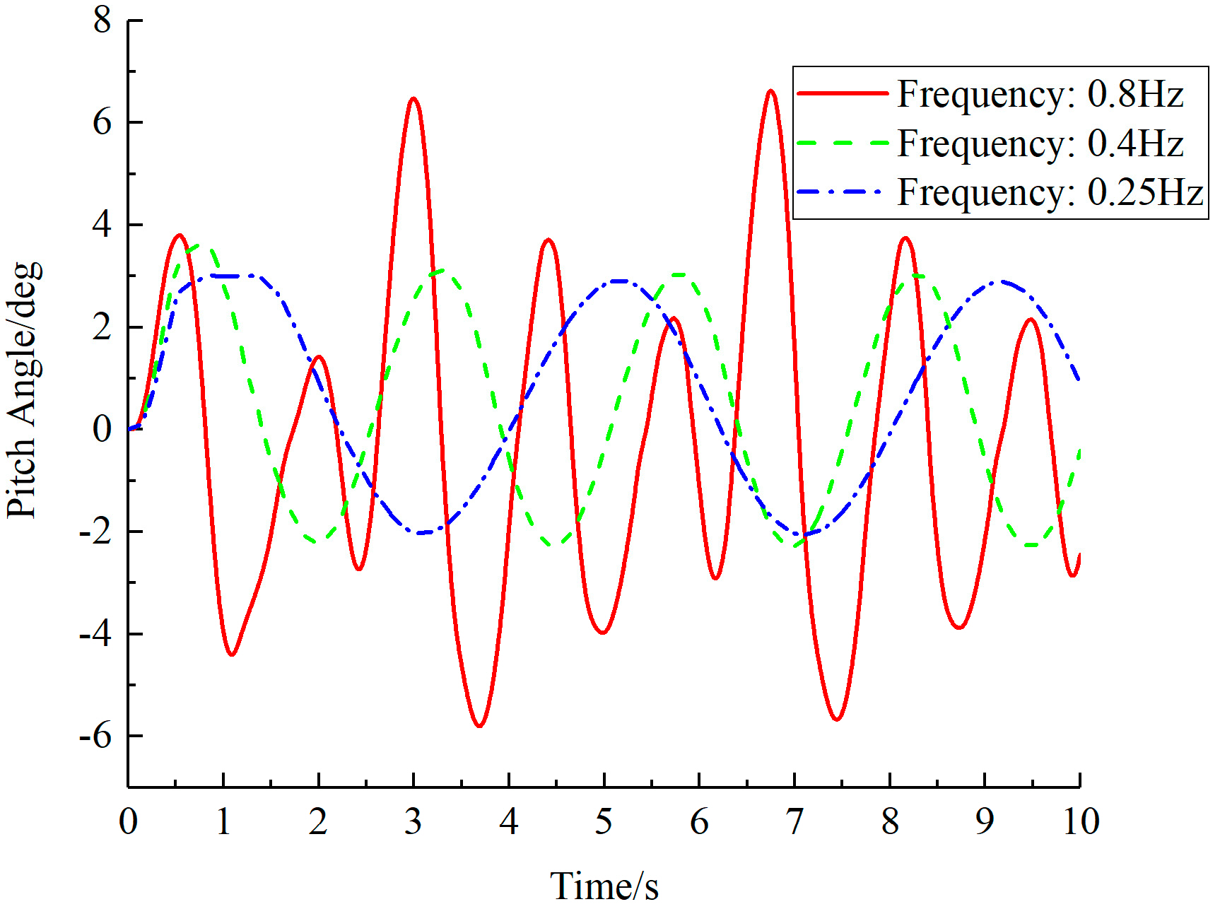
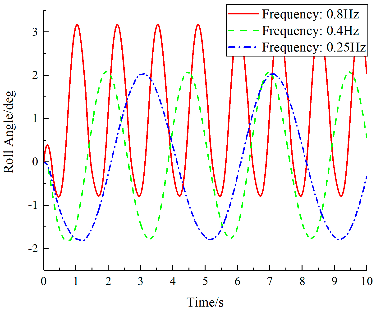
Different wave frequency domains
Sine wave impacts with an amplitude of 100 mm and frequencies of 0.8, 0.4, and 0.25 Hz are set to simulate small waves. Figure 9 shows the pitch angle response curves under impacts with different amplitudes, while Figure 10a,b present the acceleration response curves of the upper hull under impacts with various amplitudes.
From the pitch angle response, it can be observed that as the excitation frequency increases, the amplitude of the upper hull angle gradually increases, and the hull’s pitch motion intensifies. Conversely, when the excitation frequency decreases, the hull motion becomes more stable. Looking at the acceleration response, as the excitation frequency decreases, the amplitude of the hull acceleration also decreases, and the acceleration changes slow down. In the frequency domain response of acceleration, it can be seen that as the excitation frequency increases, the ship’s vibration intensifies, indicating that the suspension system is sensitive to high-frequency impacts. For head sea impacts, when the excitation frequency is lower, the parallel suspension system exhibits better vibration reduction characteristics, and the ship’s ability to adapt to waves is stronger.
The following figures show the comparison of the acceleration response between the upper hull and the pontoon under impacts with different frequencies in Figure 11a, as well as the response in the frequency domain of acceleration in Figure 11b.
As can be seen from the figures, at excitation frequencies of 0.4 and 0.25 Hz, the acceleration amplitude of the upper hull is reduced compared to the pontoon. In the frequency domain of acceleration, the vibrations of the upper hull are reduced by approximately 50% and 55.6%, respectively. As the excitation frequency decreases, the hull’s vibration reduction capability becomes stronger.
In summary, the parallel suspension system is significantly influenced by the wave grade for head sea impacts. When the wave excitation amplitude is larger, the vibration reduction effect becomes less significant. Additionally, the parallel interconnected suspension system exhibits a significant vibration reduction effect for low-frequency impacts. When facing low-frequency and high-amplitude waves, the hull’s stability and smoothness achieve good vibration reduction effects.

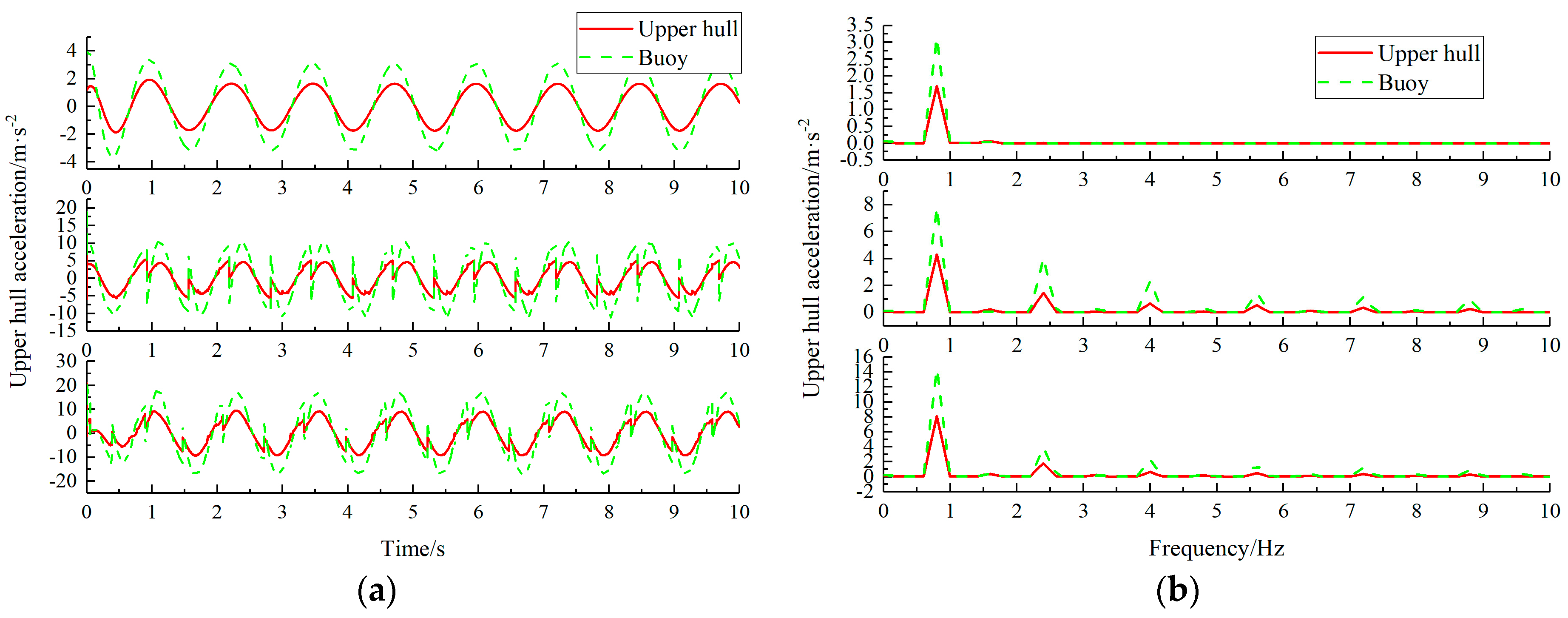
3.2.2. Horizontal Wave Impact

  • Different Wave Grades
Sine wave impacts with amplitudes of 100, 250, 400 mm and a frequency of 0.8 Hz are set. Figure 12a shows the roll angle response curves under impacts with different amplitudes, and Figure 12b presents the acceleration response curves of the upper hull under impacts with various amplitudes.
From the roll angle response, it can be observed that the roll angle response amplitudes under impacts with different amplitudes are approximately 5°, 8°, and 14°. As the excitation amplitude increases, the ship’s roll motion becomes more intense. Looking at the upper hull acceleration, it can be seen that during the initial stage of the roll motion, there is a sudden change in the hull acceleration. Moreover, as the excitation amplitude increases, the instantaneous change in the upper hull acceleration becomes more severe. Figure 13a,b show the comparison of the acceleration response between the upper hull and the pontoon under impacts with different amplitudes, as well as the response in the frequency domain of acceleration.
As can be seen from the figures, the acceleration amplitude of the upper hull is smaller than that of the pontoon. The introduction of the hydraulic interconnected suspension system has reduced the amplitude of hull vibrations. In the frequency domain of acceleration, vibrations are mainly concentrated below 10 Hz. With increasing excitation amplitude, the vibration energy levels corresponding to the various amplitudes of the upper hull and pontoon are reduced by 44.2%, 42.8%, and 42.6%, respectively. As the excitation amplitude increases, the vibration reduction performance of the suspension system is weakened to a lesser extent, indicating that the impact of beam sea waves on the suspension system is relatively small.
2.
Different Wave Frequency Domains
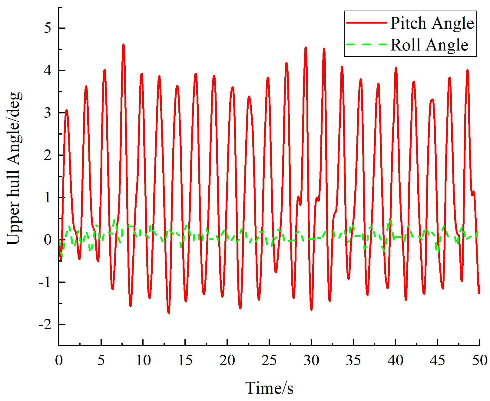
Sine wave impacts with an amplitude of 250 mm and frequencies of 0.8, 0.4, and 0.25 Hz are set. Figure 14 shows the roll angle response curves under impacts with these amplitudes, while Figure 15a,b present the acceleration response curves of the upper hull under impacts with the respective amplitudes.
Based on the roll angle response, it can be observed that as the excitation frequency decreases, the roll angle amplitude of the upper hull rapidly decreases with the fluctuations of the hull. The lower the excitation frequency is, the more stable the hull motion becomes. From the acceleration response, it can be seen that as the excitation frequency decreases, the acceleration amplitude of the hull also decreases, and the magnitude of this decrease is significant. This can be observed in the frequency domain response of the acceleration. For beam sea impacts, the lower the excitation frequency is, the better the vibration reduction characteristics of the parallel suspension system are, and the stronger the ship’s ability to adapt to waves becomes.

3.2.3. Wave Impact

Using a wave tank, a full-scale wave test was conducted on a truss-type catamaran test prototype. The test collected pontoon response data under small wave conditions, as shown in Figure 16. For ships equipped with different vibration reduction systems, their acceleration responses to the pontoon vary. Here, the experimental data are used as a reference input for simulation analysis.
Using the small wave data as input for the pontoon, a joint simulation under actual sea conditions is performed. Figure 17 shows the roll angle and pitch angle responses of the ship, while Figure 18a,b present the acceleration frequency domain response curves.
During the test, the roll angle amplitude of the ship reached 2.7°, and the pitch angle amplitude was 6°. When using the parallel suspension system, the roll angle amplitude was reduced to 0.5°, and the pitch angle amplitude was 4.5°. The anti-roll capability of the suspension system improved by 81.5%, and the anti-pitch capability improved by 25.0%. As can be seen from the figures, under wave conditions, the parallel interconnected suspension system is sensitive to pitch motion responses, resulting in poor ride comfort when the ship encounters head waves. Within the human-sensitive frequency range of 4–8 Hz, the vibration of the upper hull intensifies, leading to unsatisfactory ride comfort. However, the compensation effect for roll motion is significant. The parallel interconnected suspension system significantly reduces the roll motion amplitude, demonstrating excellent anti-roll vibration reduction capabilities. The system’s vibration impact occurs in a lower frequency range.

4. Experimental Research

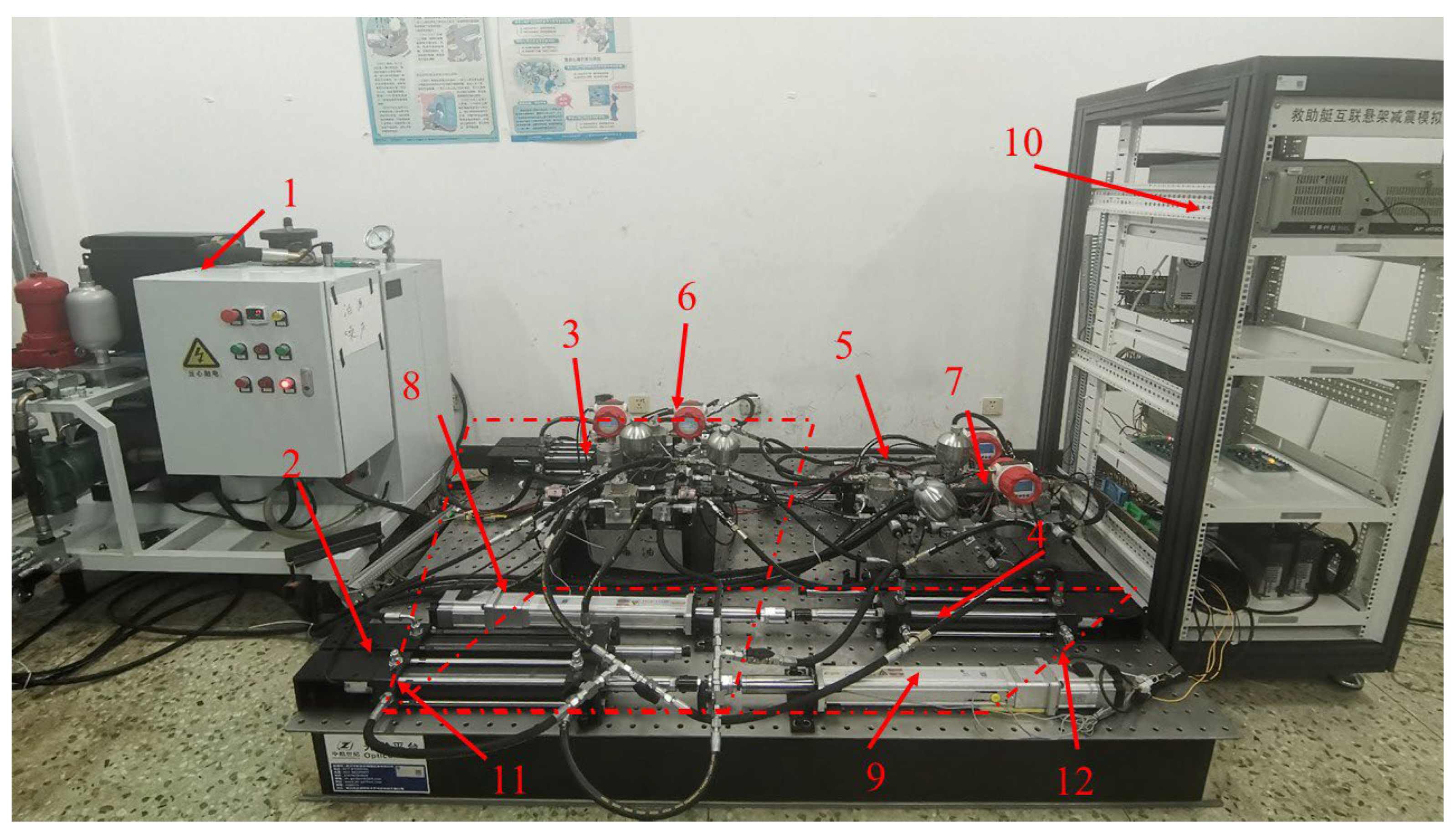
4.1. Test Bench Construction

The experimental setup in this study primarily consists of a hydraulic system, a mechanical system, and a measurement and control system, including a test bench and valve control devices. The hydraulic system is primarily used to adjust the position of the hydraulic cylinders and control the switching of the hydraulic circuits. The mechanical system is responsible for fixing the hydraulic cylinders, connecting the servo motor to the piston rods of the hydraulic cylinders, and coupling the piston rods together. The measurement and control system collects data on circuit pressure, flow rate, and hydraulic cylinder displacement signals; controls the switching of the hydraulic circuits through the control of one-way valves; and regulates the excitation output of the servo motor. The test bench is illustrated in Figure 19, and the main component information of the test bench is presented in Table 3.

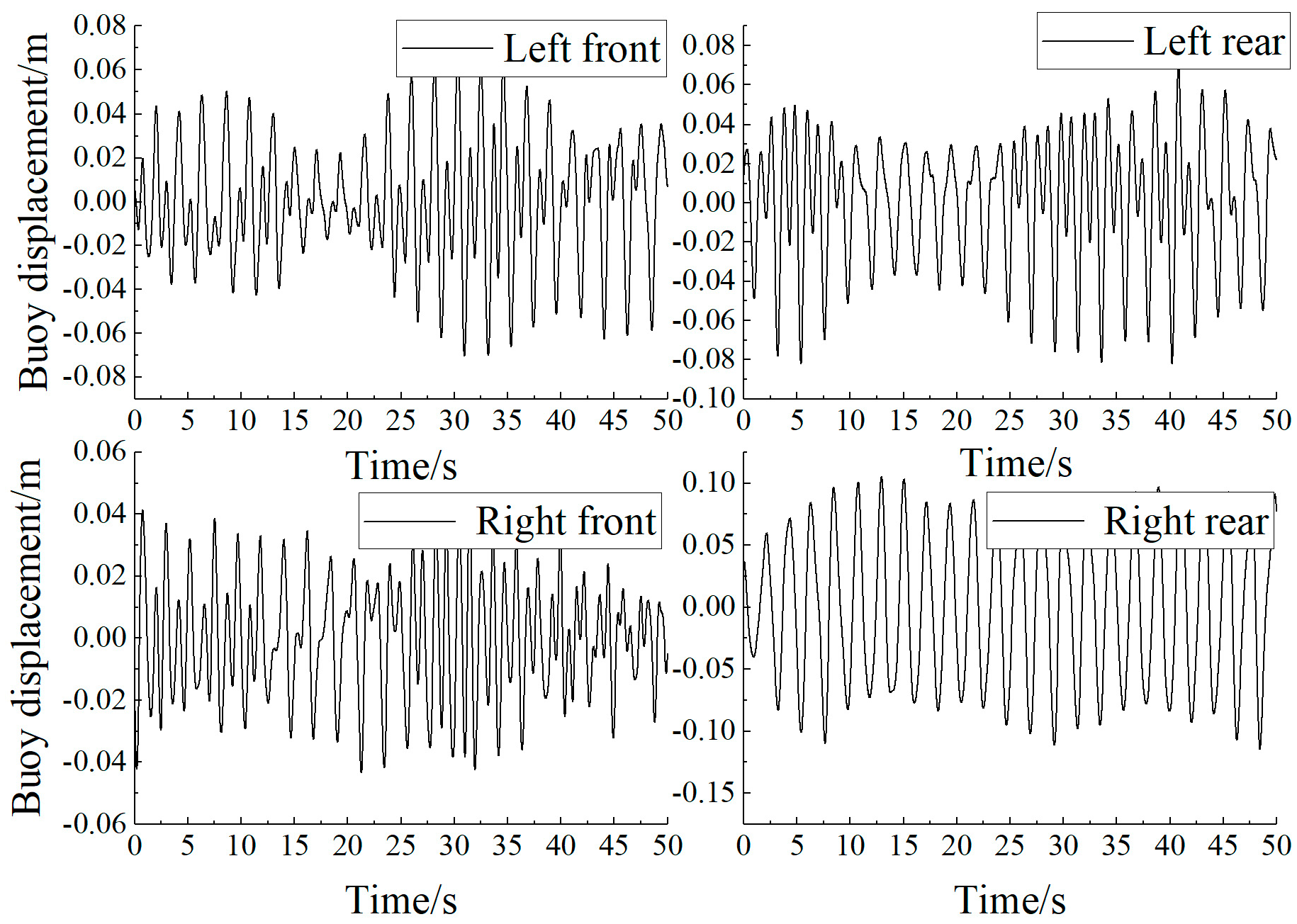
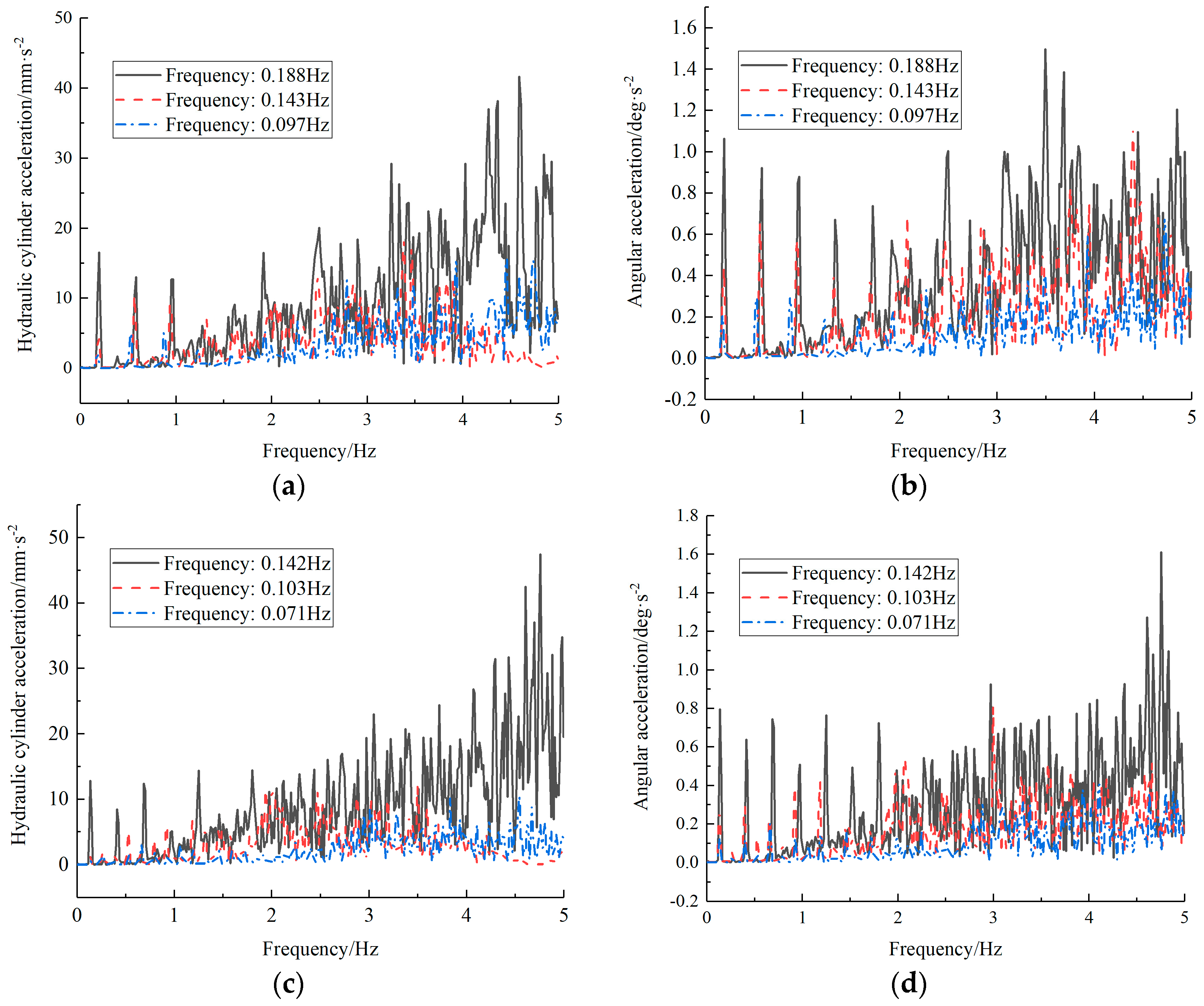
4.2. Research on Coupling Test of Interconnected Suspension

The experimental setup consists of a set of anti-pitch interconnected loops and a set of anti-roll interconnected loops. Focusing on the parallel interconnected suspension system proposed for enhancing the wave adaptability of rescue vessels, this study conducts a 1/2 parallel interconnected suspension system excitation test. Specifically, hydraulic cylinders 1-1 and 2-1 are mechanically connected, while hydraulic cylinders 1-3 and 2-3 are also mechanically connected. Through the valve control system, the anti-pitch loop and the anti-roll loop are disconnected separately. Different amplitudes and frequencies of excitation output are set for servo motor 1 to simulate the working sea conditions when the 1/2 suspension system receives wave excitation, as shown in Figure 20.
  • Different amplitudes
The output amplitudes of the servo motor are set to 30, 50, and 70 mm, and the displacement responses of the hydraulic cylinders are shown in Figure 21a,b.
As shown in the figures, the parallel hydraulic cylinder group exhibits weaker compensation ability for positive impacts. At amplitudes of 50 and 70 mm, the displacement compensations are approximately 4.4% and 8.8%, respectively. However, there is a pressure error during the positive test at 30 mm, so it is excluded. During negative impacts, the displacement compensation amplitude of the suspension system is around 39.1%, 49.9%, and 56.7%. This indicates that the suspension system has stronger compensation capability for negative impacts. The compensation capabilities of the suspension system are summarized in Table 4.
2.
Different frequencies
We have selected and analyzed the test results obtained at different frequencies with excitation amplitudes of 50 and 70 mm. The test results are presented in Figure 22a–d.
As can be seen from the figures, with the decrease in excitation frequency, the amplitude of the hydraulic cylinder’s displacement response also decreases, indicating that the suspension system’s displacement compensation capability decreases with lower excitation frequencies. A frequency domain analysis of acceleration and angular acceleration for the hydraulic cylinder displacement response of the parallel interconnected suspension system is conducted, and the results are shown in Figure 23a,b.
From the figures, it is evident that the parallel interconnected suspension system experiences an increase in the vibration amplitude of the suspension system as the excitation frequency increases. The acceleration response amplitude at the low frequency of 0.071 Hz is approximately 75% of that at 0.142 Hz. The equivalent angular acceleration frequency domain amplitude response follows the same trend, indicating that the parallel interconnected suspension system is not sensitive to low-frequency impacts. Both the stability and damping performance of the suspension system show good results.
The test results demonstrate that the parallel interconnected suspension system is insensitive to low-frequency impacts and combines the relative advantages of anti-pitch and anti-roll interconnection. Both the stability and damping performance of the suspension system exhibit excellent performance, proving the feasibility and superiority of the parallel interconnected suspension system for practical sea conditions.

5. Conclusions

In addressing the challenges of complex coupling, increased difficulty in system control, increased number of intermediate components, and difficulties in theoretical research within interconnected suspension systems, this study proposes a parallel decoupled suspension system based on the multi-scenario analysis using ADAMS-AMESim co-simulation and the experimental research on the coupling characteristics of hydraulic interconnected suspensions. The main conclusions are as follows:
  • When faced with simultaneous impacts from crosswaves and headwaves, the parallel interconnected suspension system exhibits excellent anti-roll performance. Compared to traditional truss-type rescue vessels, the suspension system achieves an 81.5% improvement in anti-roll capability and a 25.0% improvement in anti-pitch capability. The suspension system is greatly influenced by headwave impacts and wave levels, and it exhibits significant damping effects on low-frequency impacts. Compared to previous interconnected loops, the parallel interconnected suspension system reduces the coupling of suspension loops, decreases the number of intermediate components, lowers costs, and simplifies system control. When facing low-frequency and high-amplitude waves, the suspension system maintains good stability and ride comfort with excellent damping effects.
  • The 1/2 parallel interconnected suspension system achieves approximately 40% displacement compensation, demonstrating its insensitivity to low-frequency impacts. By combining the relative advantages of anti-pitch and anti-roll interconnection, the suspension system exhibits good stability and damping performance, proving the feasibility and superiority of the parallel interconnected suspension system for practical sea conditions.
  • The simulation models used in this paper are all mechanical structures for theoretical motion, without a detailed consideration of the hull structure in the actual ship design and manufacture, and no real ship sea test was conducted. Future research work can be carried out to fabricate the real ship prototype and verify the vibration-damping performance of the suspension system proposed in this paper through a real ship sailing test.

Author Contributions

Writing—original draft, X.M. and W.W.; writing—review & editing, X.M., H.D. and W.W.; methodology, H.D. and W.X. All authors have read and agreed to the published version of the manuscript.

Funding

This research was funded by the National Natural Science Foundation of China (Grant No. 52075065) and the National Key R&D Program of China (Grant No. 2022YFC3006004).

Data Availability Statement

The data presented in this study are available upon request from the corresponding authors.

Conflicts of Interest

The authors declare no conflict of interest.

References

  1. Fratello, J.; Ahmadian, M. Multi-body dynamic simulation and analysis of wave-adaptive modular vessels. In Proceedings of the 11th International Conference on Fast Sea Transportation, Honolulu, HI, USA, 26–29 September 2011. [Google Scholar]
  2. Peterson, A.W. Simulation and Testing of Wave-Adaptive Modular Vessels; Virginia Tech: Blacksburg, VA, USA, 2014. [Google Scholar]
  3. Pandey, J.; Hasegawa, K. Study on turning manoeuvre of catamaran surface vessel with a combined experimental and simulation method. IFAC-PapersOnLine 2016, 49, 446–451. [Google Scholar] [CrossRef]
  4. Conti, U.; Gundersen, M. Second generation design of wave adaptive modular vessels (WAM-V). In Proceedings of the 11th International Conference on FAST2011, Honolulu, HI, USA, 26–29 September 2011. [Google Scholar]
  5. Velodyne Marine—Chasing Martini 1.5 on San Francisco Bay. 2024. Available online: https://www.boats.com/reviews/the-velodyne-martini-1-5-active-suspension-on-a-boat/ (accessed on 18 March 2013).
  6. Nauti-Craft Marine Suspension Technology. 2017. Available online: https://www.youtube.com/watch?v=kCgVumRpLro (accessed on 5 September 2016).
  7. Han, J.; Maeda, T.; Kinoshita, T.; Kitazawa, D. Towing test and motion analysis of motion controlled ship—Based on an application of skyhook theory. In Proceedings of the 12th International Conference on the Stability of Ships and Ocean Vehicles (STAB2015), Glasgow, Scotland, 14–19 June 2015. [Google Scholar]
  8. Myers, S.; Dobbins, T.; King, S.; Hall, B.; Gunston, T.; Holmes, S.; Dyson, R. The effectiveness of shock mitigation technology in reducing motion induced fatigue in small high speed craft. In Proceedings of the Pacific International Maritime Conference (IMC), Sydney, Australia, 29–31 January 2008. [Google Scholar]
  9. Han, J.; Maeda, T.; Itakura, H.; Kitazawa, D. Experimental study on the wave energy harvesting performance of a small suspension catamaran exploiting the maximum power point tracking approach. Ocean Eng. 2022, 243, 110176. [Google Scholar] [CrossRef]
  10. Han, J.; Kitazawa, D.; Kinoshita, T.; Maeda, T.; Itakura, H. Experimental investigation on a cabin-suspended catamaran in terms of motion reduction and wave energy harvesting by means of a semi-active motion control system. Appl. Ocean Res. 2019, 83, 88–102. [Google Scholar] [CrossRef]
  11. Wilde, J.R.; Heydinger, G.J.; Guenther, D.A.; Mallin, T.; Devenish, A.M. Experimental evaluation of fishhook maneuver performance of a kinetic suspension system. SAE Trans. 2005, 392, 387–396. [Google Scholar]
  12. Wilde, J.R.; Heydinger, G.J.; Guenther, D.A. Adams simulation of ride and handling performance of the kinetic suspension. SAE Tech. Pap. 2006, 1972, 1646–4659. [Google Scholar]
  13. Smith, W.A.; Zhang, N. Recent developments in passive interconnected vehicle suspension. Front. Mech. Eng. China 2010, 5, 1–18. [Google Scholar] [CrossRef]
  14. Carlomagno, F. Modeling and Simulation of a Hydraulic Interconnected Suspension System for Automotive Applications. Doctoral Dissertation, Politecnico di Torino, Torino, Italy, 2020. [Google Scholar]
  15. Zapletal, E. Balanced Suspension; SAE Technical Paper; SAE International: Warrendale, PA, USA, 2000. [Google Scholar]
  16. i Buj, J.F. Integral suspension system for motor vehicles based on passive components. SAE Trans. 2002, 3105, 761–774. [Google Scholar]
  17. Smith, M.C.; Walker, G.W. Interconnected vehicle suspension. Proc. Inst. Mech. Eng. Part D. J. Automob. Eng. 2005, 219, 295–307. [Google Scholar] [CrossRef]
  18. Mavroudakis, B.; Eberhard, P. Mode decoupling in vehicle suspensions applied to race cars. In Proceedings of the III European Conference on Computational Mechanics: Solids, Structures and Coupled Problems in Engineering, Lisbon, Portugal, 1 January 2006. [Google Scholar]
  19. Wang, W.; Du, H.; Xiong, W.; Nie, Y. Sensitivity Analysis and Optimization of the Hydraulic Interconnected Suspension Damping System of a Small Rescue Craft. J. Mar. Sci. Eng. 2023, 11, 1857. [Google Scholar] [CrossRef]
  20. Zhang, N.; Smith, W.A.; Jeyakumaran, J. Hydraulically interconnected vehicle suspension: Background and modelling. Veh. Syst. Dyn. 2010, 48, 17–40. [Google Scholar] [CrossRef]
  21. Zhang, N.; Wang, L.; Hu, W. Handling analyses of a vehicle fitted with a roll-resistant hydraulically interconnected suspension. In Proceedings of the International Association of Vehicle System Dynamics Symposium, Manchester, UK, 12–14 April 2011. [Google Scholar]
Figure 1. Schematic diagram of parallel interconnected suspension system. 1-1, -2, -3, and -4: Hydraulic cylinders R1, R2, R3, and R4; 2-1, -2, -3, and -4: Hydraulic cylinders P1, P2, P3, and P4; 3-1~20: Damping valves; 4-1, -2, -3, and -4: Accumulator RA, Accumulator PB, Accumulator PA, and Accumulator RB.
Jmse 12 01074 g001
Figure 2. (a) Schematic diagram of the impact principle of transverse waves; (b) schematic diagram of the impact principle of top waves.
Jmse 12 01074 g002
Figure 3. AMESim-ADAMS co-simulation flow chart.
Jmse 12 01074 g003
Figure 4. ADAMS-AMESim co-simulation model schematic diagram.
Jmse 12 01074 g004
Figure 5. (a) Parallel interconnection co-simulation model (front suspension and rear suspension); (b) parallel interconnection co-simulation model (left suspension and right suspension).
Jmse 12 01074 g005
Figure 6. (a) Schematic diagram of crest wave impact; (b) schematic diagram of transverse wave impact.
Jmse 12 01074 g006
Figure 7. (a) Pitch angle response of upper hull; (b) acceleration response of upper hull.
Jmse 12 01074 g007
Figure 8. Frequency domain response of acceleration of upper hull.
Jmse 12 01074 g008
Figure 9. Pitch angle response of upper hull.
Jmse 12 01074 g009
Figure 10. (a) Acceleration response of upper hull; (b) frequency domain response of acceleration of upper hull.
Jmse 12 01074 g010
Figure 11. (a) Acceleration response of upper hull; (b) frequency domain response of acceleration of upper hull.
Jmse 12 01074 g011
Figure 12. (a) Roll angle response of upper hull; (b) acceleration response of upper hull.
Jmse 12 01074 g012
Figure 13. (a) Acceleration response of upper hull; (b) frequency domain response of acceleration of upper hull.
Jmse 12 01074 g013
Figure 14. Roll angle response of upper hull.
Jmse 12 01074 g014
Figure 15. (a) Acceleration response of upper hull; (b) frequency domain response of acceleration of upper hull.
Jmse 12 01074 g015
Figure 16. Small wave displacement data of buoy.
Jmse 12 01074 g016
Figure 17. Upper hull angular response.
Jmse 12 01074 g017
Figure 18. (a) Acceleration response of upper hull; (b) frequency domain response of acceleration of upper hull.
Jmse 12 01074 g018
Figure 19. The 8-cylinder hydraulic interconnection system test bench. 1, hydraulic pump station; 2, hydraulic cylinder group 1; 3, hydraulic cylinder group 2; 4, hydraulic cylinder group 3; 5, hydraulic cylinder group 4; 6, valve group 1; 7, valve group 2; 8, servo cylinder 1; 9, servo cylinder 2; 10, industrial computer; 11, front overhang; 12, left overhang.
Jmse 12 01074 g019
Figure 20. Schematic diagram of 1/2 parallel interconnected suspension.
Jmse 12 01074 g020
Figure 21. (a) Hydraulic cylinder displacement response (positive impact); (b) hydraulic cylinder displacement response (negative impact).
Jmse 12 01074 g021
Figure 22. (a) Hydraulic cylinder displacement response (positive amplitude 50 mm); (b) hydraulic cylinder displacement response (negative amplitude 50 mm); (c) hydraulic cylinder displacement response (positive amplitude 70 mm); (d) hydraulic cylinder displacement response (negative amplitude 50 mm).
Jmse 12 01074 g022
Figure 23. (a) Frequency domain response of hydraulic cylinder acceleration (forward amplitude: 50 mm); (b) frequency domain response of equivalent angular acceleration (negative amplitude: 50 mm); (c) frequency domain response of hydraulic cylinder acceleration (forward amplitude: 70 mm); (d) frequency domain response of equivalent angular acceleration (negative amplitude: 70 mm).
Jmse 12 01074 g023
Table 1. ADAMS stiffness damping parameters.
UnitValueQuantity
Upper hull820 kg1
Buoy340 kg2
Hydraulic cylinder20 kg4
Spring dampingStiffness25.153 N∙mm−14
Damping2.132 N∙s∙mm−14
Table 2. Main parameters of hydraulic interconnected suspension system.
ArgumentValueUnits
Hydraulic cylinder inner diameter/D40mm
Hydraulic cylinder rod diameter/d22mm
Cylinder stroke/L−200–200mm
Accumulator volume/V00.35L
Accumulator pre-charge pressure/Pgas1.5MPa
Throttle aperture/r10mm
Front/rear suspension mass/m1410kg
Left/right hanging mass/m2410kg
Static friction force/F600N
System dynamic friction coefficient/Vf50N·mm·s−1
Table 3. Main component information.
NumberNameModel NumberMain ParameterQuantity
1Hydraulic pumpYBZ-20-17SMaximum flow rate 35 L/min Maximum pressure 17 MPa Tank volume 160 L1
2Servo valveFF-131/100 MKZ801F.14-115Servo amplifier MK2801F.144
3Proportional valveKKDSR1PB/HCG24N0K4V0–24 V DC control voltage2
4accumulatorGXQB 3.5 L/21 MPa LYNominal volume 3.5 L4
5flowmeterWT10VGALB0–5 V voltage signal4
6Solenoid valveDTDF-MC(H)N-224 34 L/min T-162AMaximum flow rate 40 L/min Maximum pressure 35 MPa16
7Pressure sensorMIK-P300-2.5 MPa-V1-B4-C1-J1P10–5 V voltage signal4
8Displacement sensorKYDM-L0–24 V voltage signal8
9Hydraulic cylinderSFQ50/36-300NZ1DInner/outer diameter: 30 mm/50 mm stroke 300 mm8
10Servo cylinderXINJE DS5F-20P7-PTARated power 750 kw maximum output power 6 kN2
Table 4. Displacement compensation of 1/2 parallel connected suspension system.
Excitation amplitude30 mm50 mm70 mm
Wave class1 class2 class3 class
Displacement compensationForward impact15.0%4.4%8.8%
Negative impact39.1%49.9%56.7%
Disclaimer/Publisher’s Note: The statements, opinions and data contained in all publications are solely those of the individual author(s) and contributor(s) and not of MDPI and/or the editor(s). MDPI and/or the editor(s) disclaim responsibility for any injury to people or property resulting from any ideas, methods, instructions or products referred to in the content.

