Model Tests on the Frequency Responses of Offshore Monopiles

Abstract
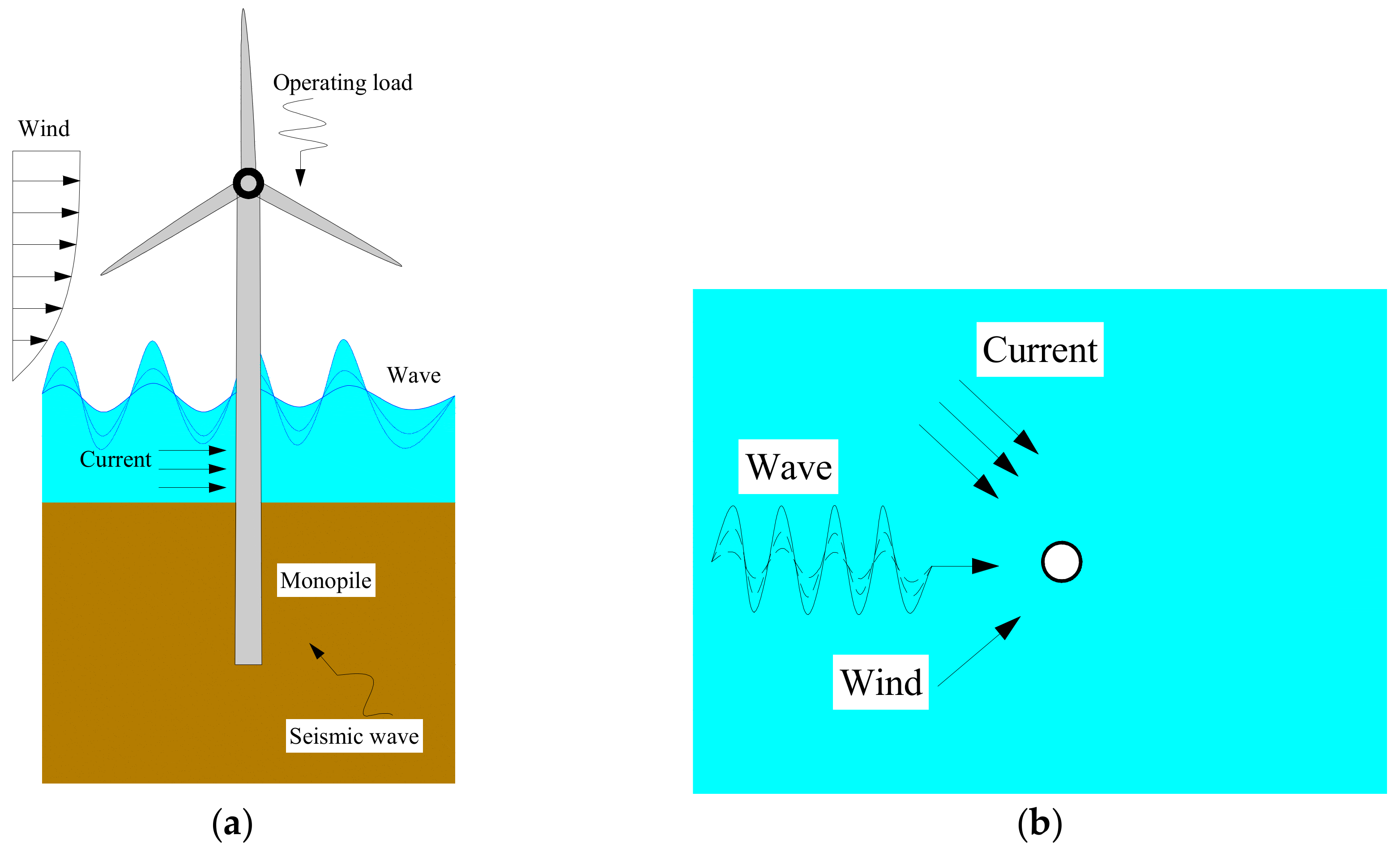
:1. Introduction
2. Similitude Relationships
- (1)
- Geometric parameters: He et al. [13] pointed out that the dynamic impedances of a monopile are related to the embedded aspect ratio L/D, the elastic modulus ratio between pile and soil (Ep/Es) and the thickness–diameter ratio (h/D). The length–diameter ratio (L/D) of modern monopiles used in offshore wind turbines is very small, from 3 to 8. The thickness–diameter ratio (h/D) is about 0.01. As a result, the L/D of the model pile in the test is chosen as 5, and h/D is 0.01.
- (2)
- Ep/Es: For cohesionless soil, when the shear strain amplitude is less than 10−4, the shear modulus G0 is mainly related to the void ratio e and the average effective principal stress σm’ [40]. For round sand (e < 0.8), G0 can be estimated aswhere e is the void ratio related to the relative density Dr. For fixed relative density, σm’ is proportional to the depth hs. The average elastic modulus of soil Es is simplified to the elastic modulus of sand at the depth of around 0.5–1.0 D, for simplicity. The pile is made of steel Ep = 200 GPa, so (Ep/Es)model ≈ 10,000–20,000, while Es in the prototype is about 10–250 MPa, with (Ep/Es)prototype ≈ 840–21,000, which means monopiles in both the model and prototype act like rigid piles. However, tests in loose sand (Dr = 10%, Ep/Es ≈ 21,000) and dense sand (Dr = 88%, Ep/Es ≈ 13,000) are conducted to investigate the influence of the elastic modulus ratio.
- (3)
- Dimensionless frequency (a0): According to soil dynamics, the responses are frequency-dependent, and the nondimensional frequency is especially useful when analyzing the obtained results, where r is the radius of the pile, ω is the circular frequency of the load, μs is the shear modulus of the soil, and ρs is the density of the soil. a0 has been chosen including 0–0.5 in accordance with most pile dynamic analysis works.
3. Experimental Formulation
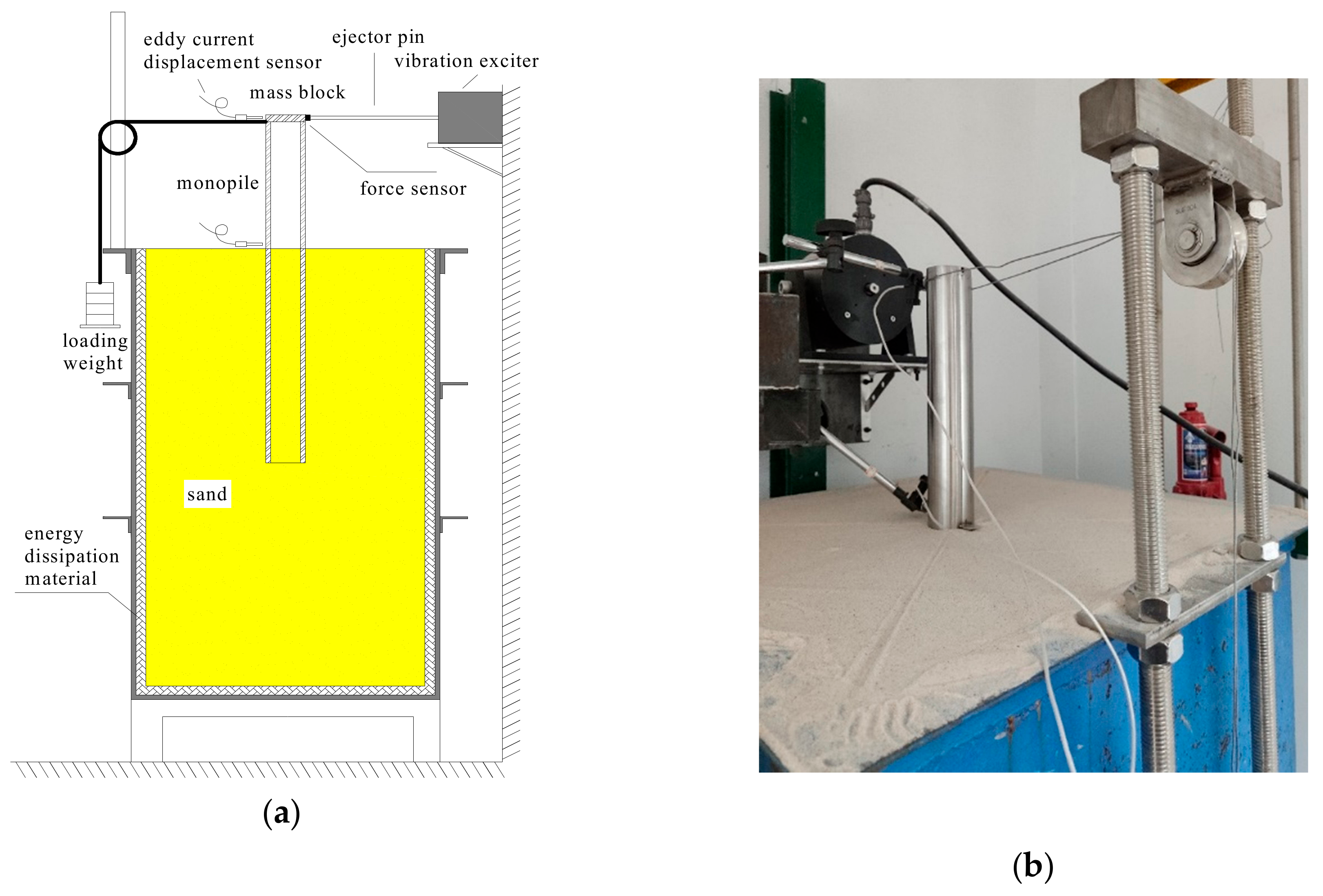
3.1. Test Platform
3.2. Test Series
- (1)
- LBC: the lateral bearing capacity test in loose sand (Dr = 10%, L.LBC) and dense sand (Dr = 88%, D.LBC).
- (2)
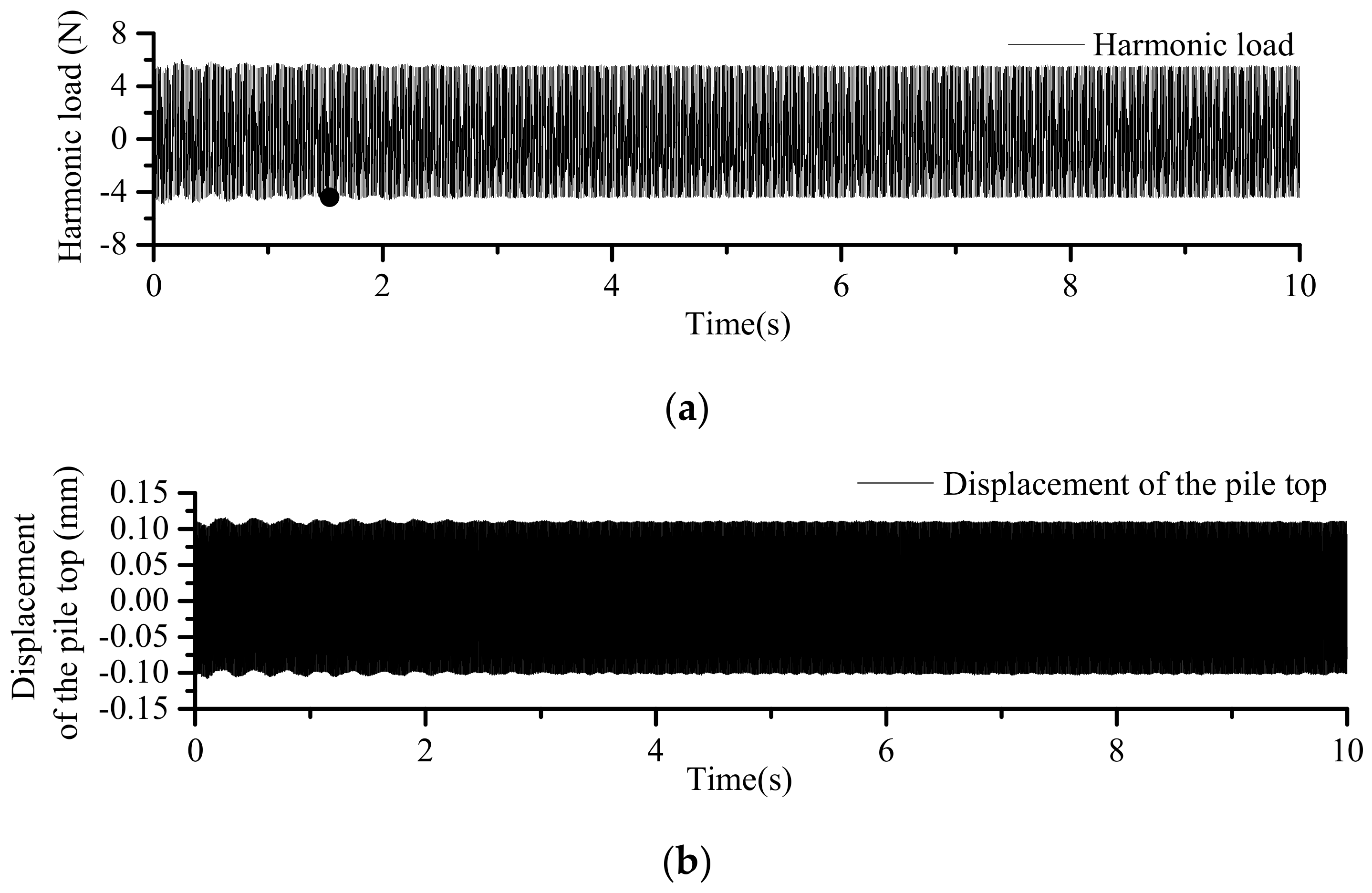
- HL: vibration characteristic test of monopile foundation under harmonic loads with different amplitudes. Harmonic loads with different frequencies and fixed amplitudes are applied to the pile top, and the displacements and the loads are measured. Then, change the amplitude of the loads from 1 N to 5 N in the dense sand case, and from 0.5 N to 10 N in the loose sand case.
- (3)
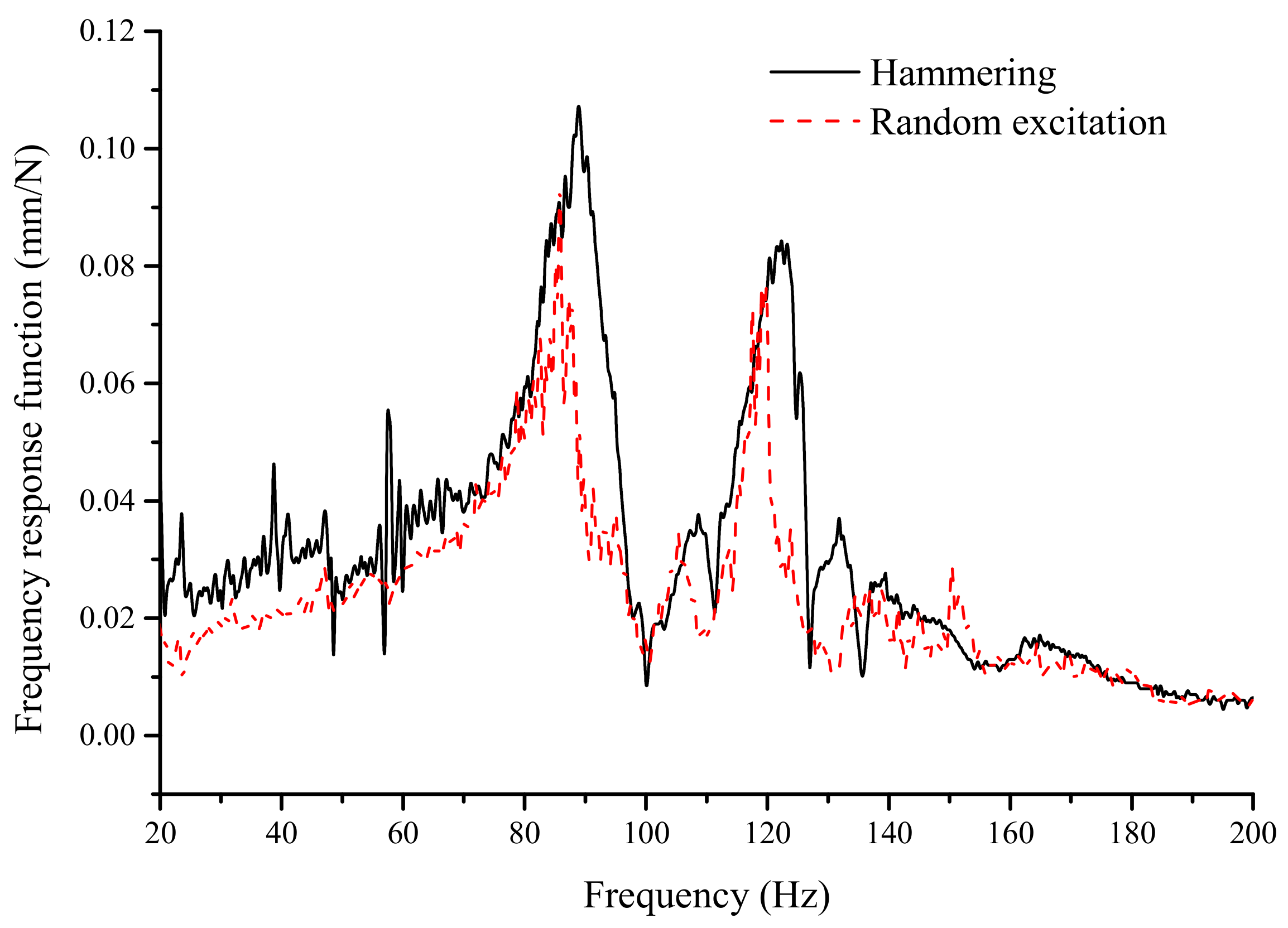
- SL: the influence of the lateral static load on the vibration characteristics by hammer excitation with FRF method.
- (4)
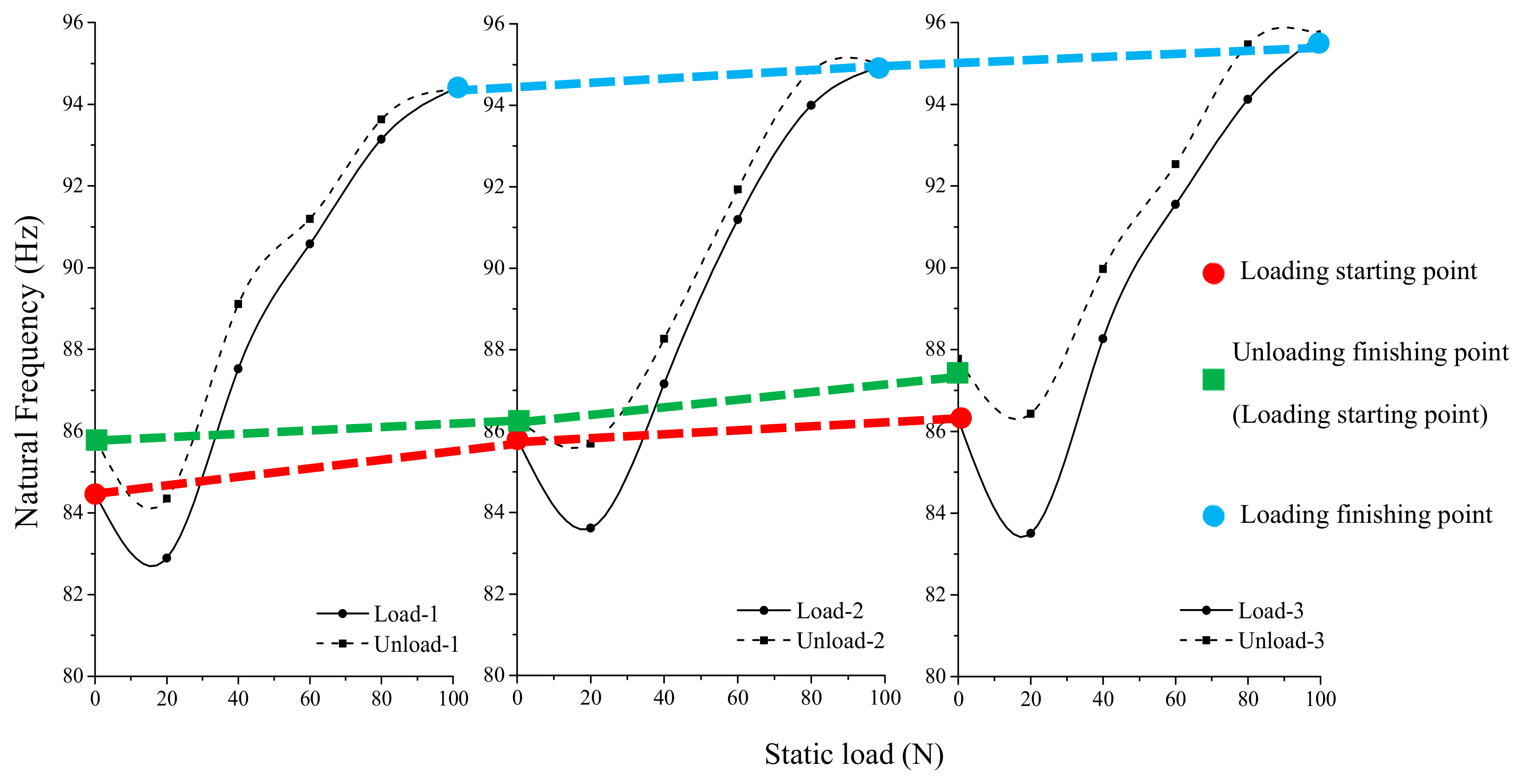
- L-U: three repeated loading-unloading processes to comprehend how extreme static loads influence the vibration characteristics of the pile.
- (5)
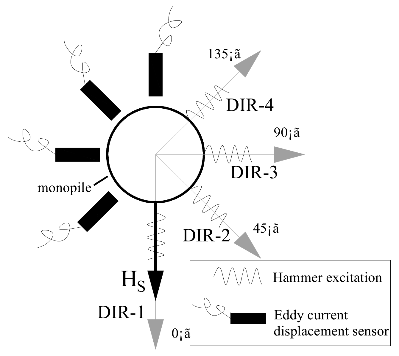
- S-D: the influence of the static load on the vibration characteristics in different directions.
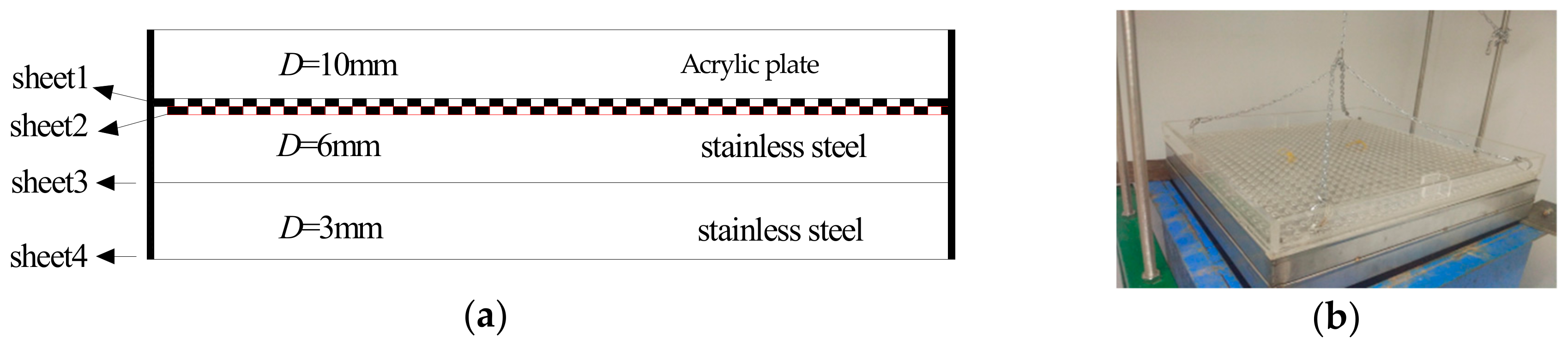
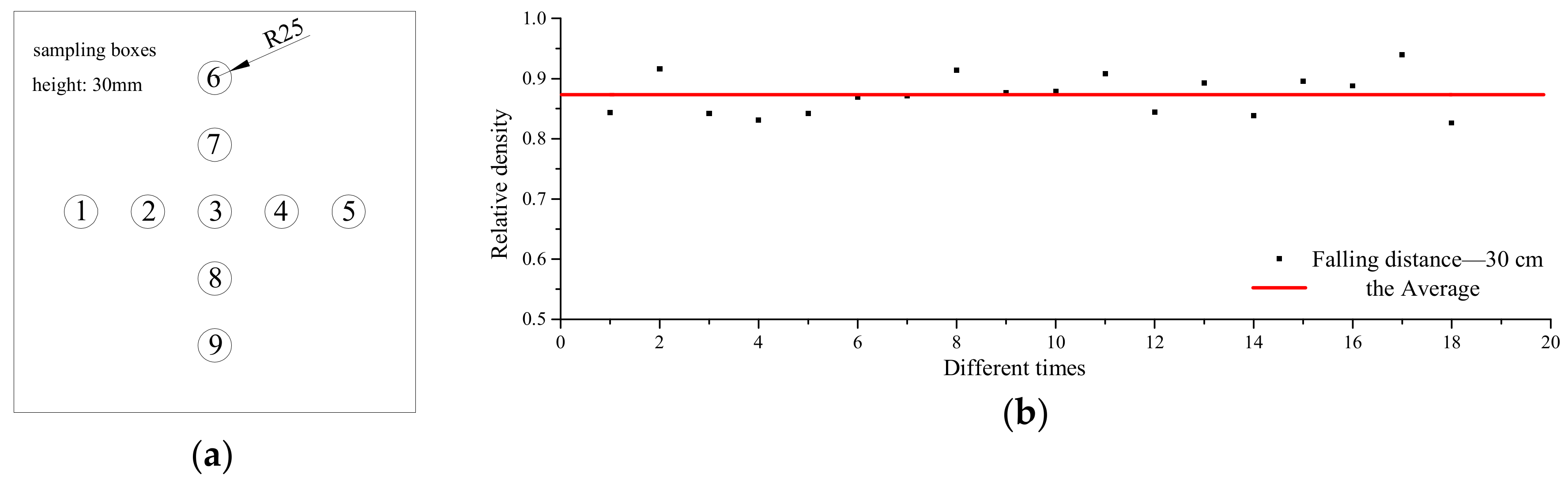
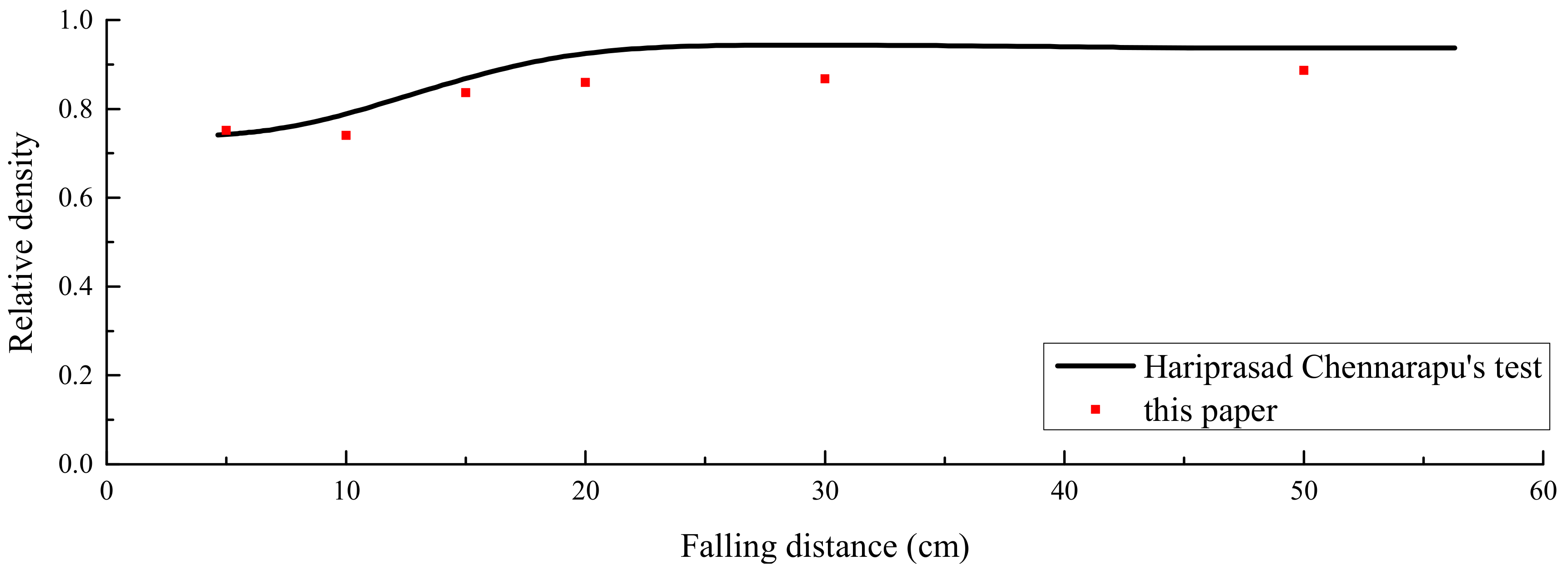
3.3. Preparation of the Sand
4. Test Results
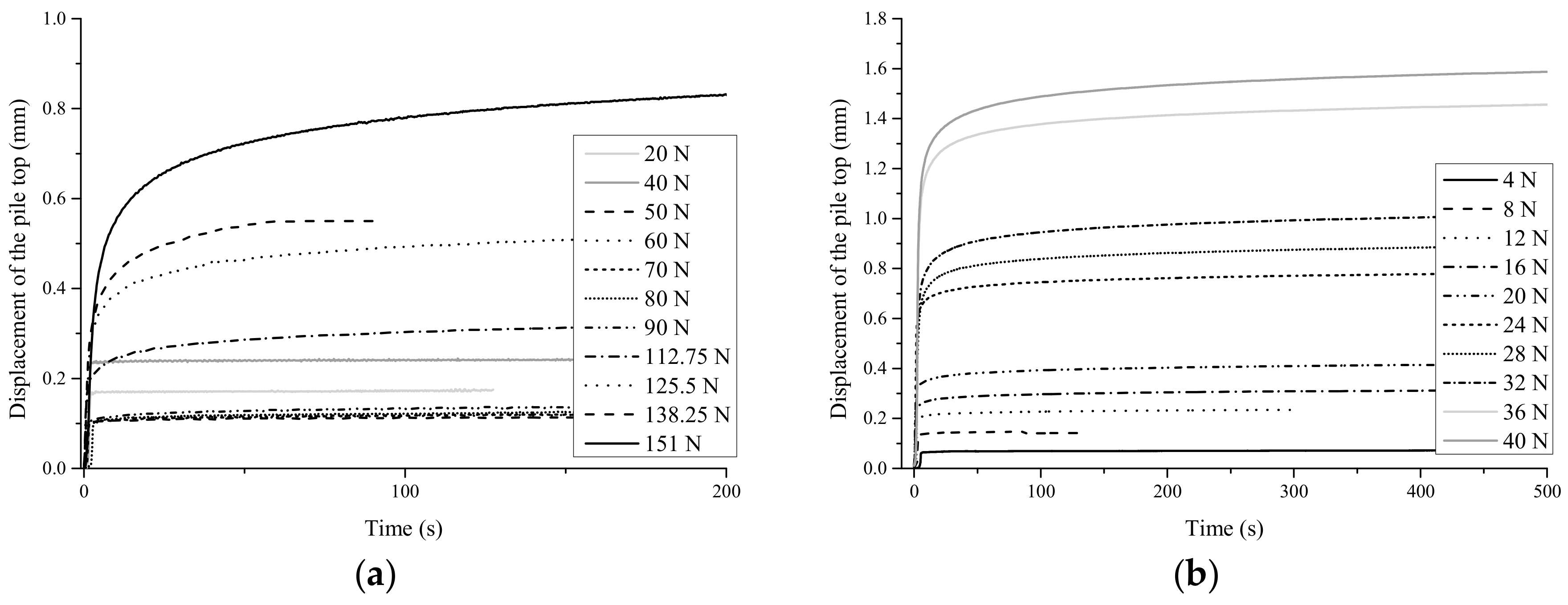
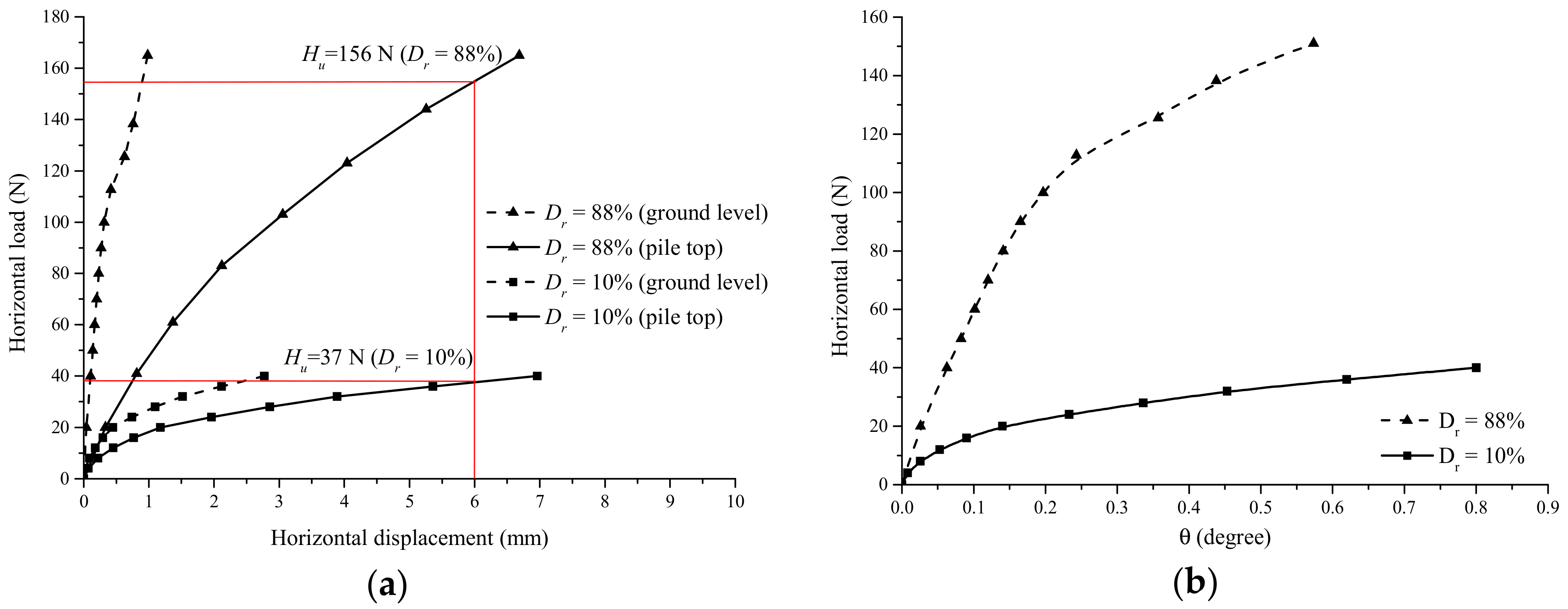
4.1. Horizontal Bearing Capacity
4.2. Vibration Characteristics under Dynamic Loading with Different Amplitudes
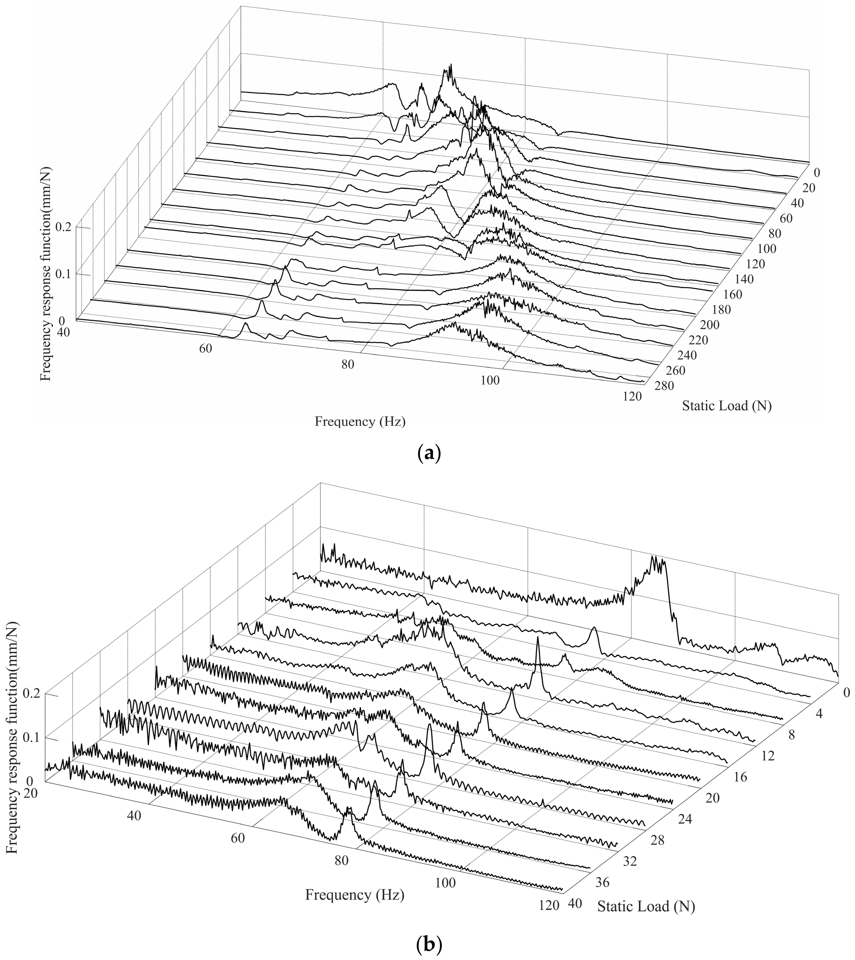
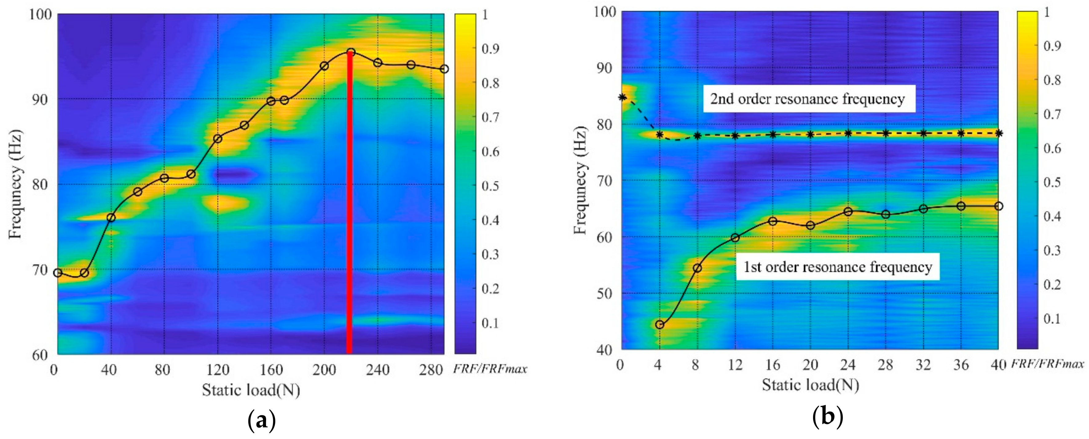
4.3. Vibration Characteristics under Different Static Loads
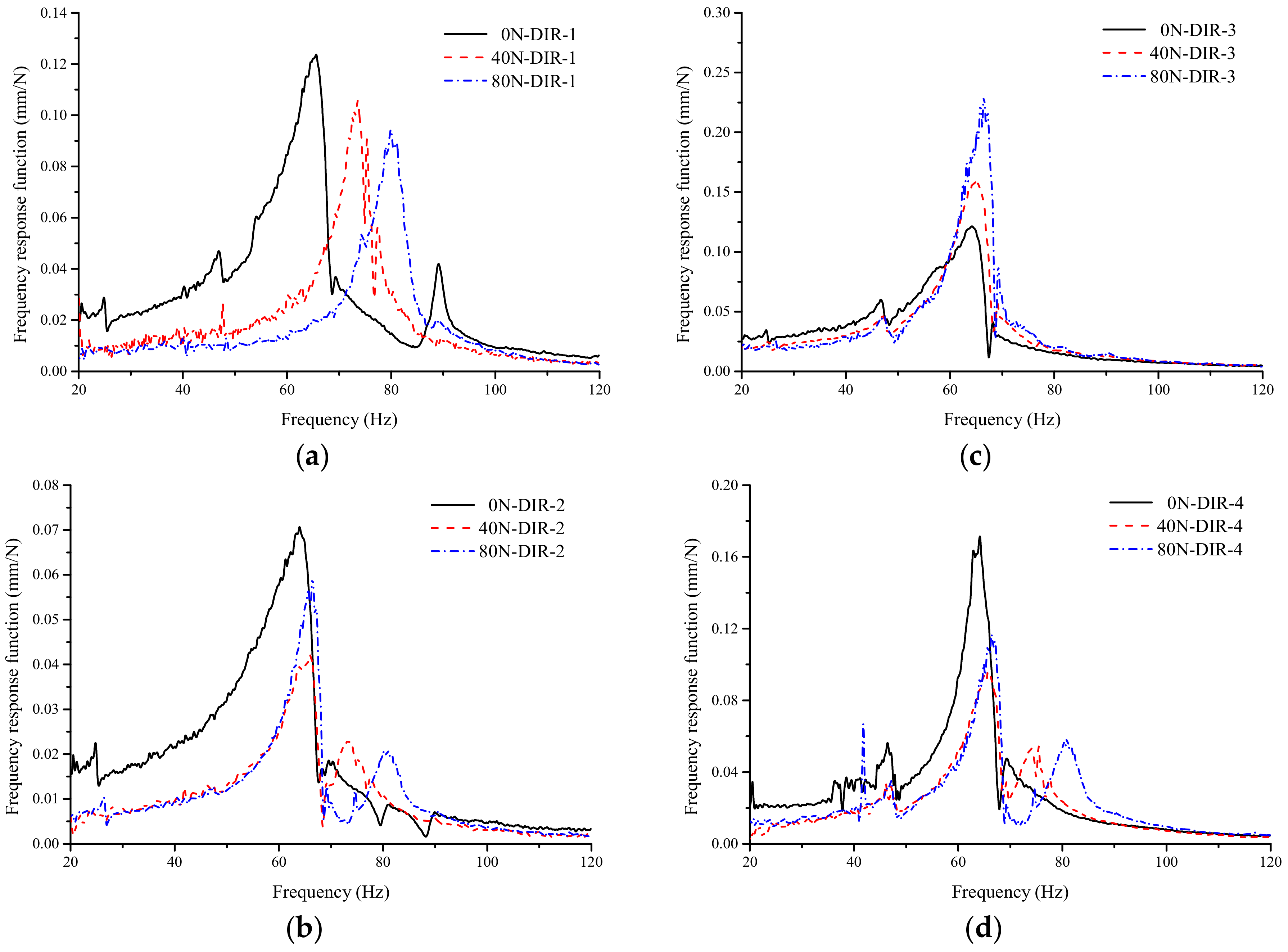
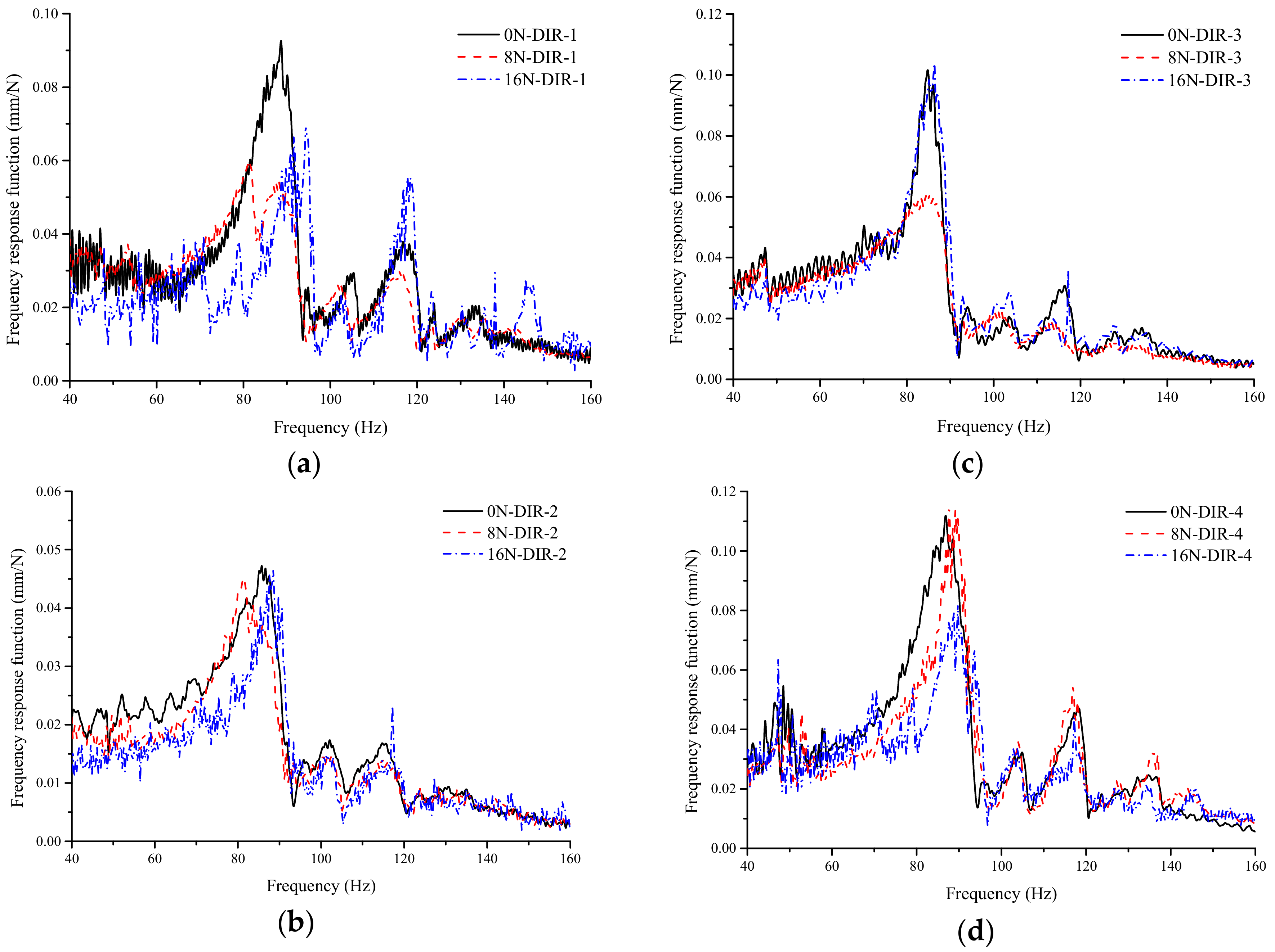
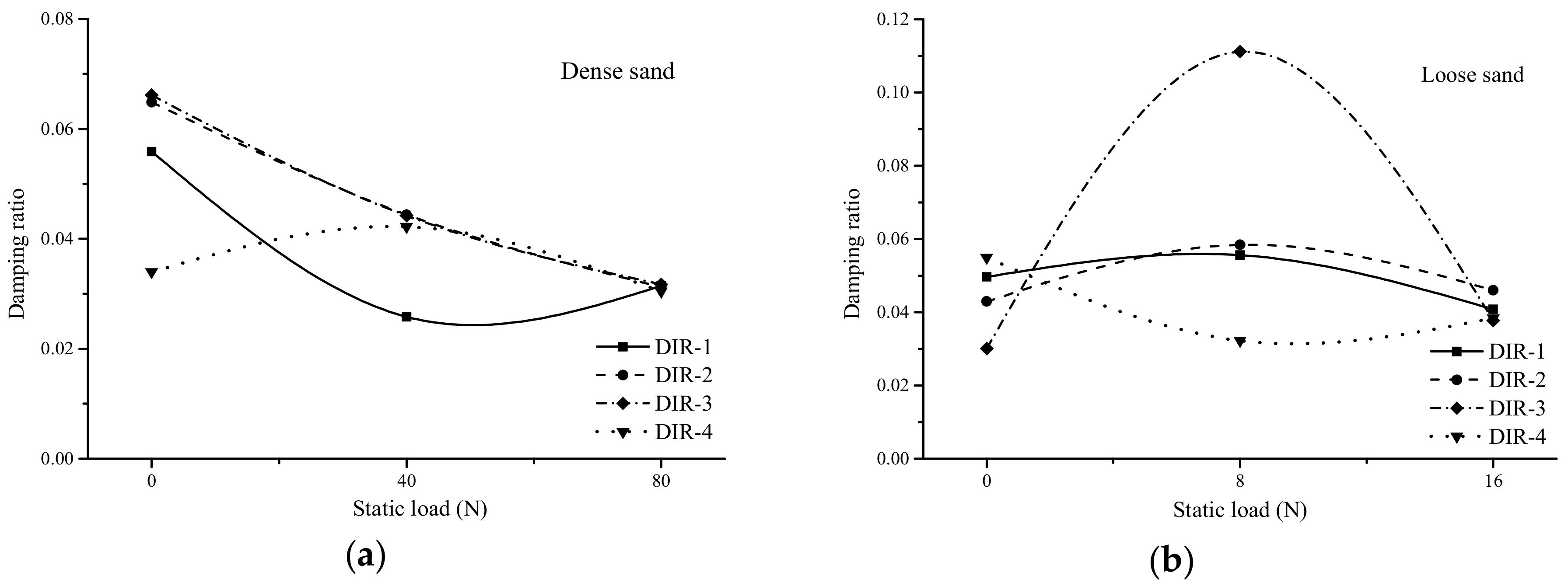
4.4. Vibration Characteristics in Different Directions under Different Static Loads
5. Conclusions and Outlook
5.1. Conclusions
- (1)
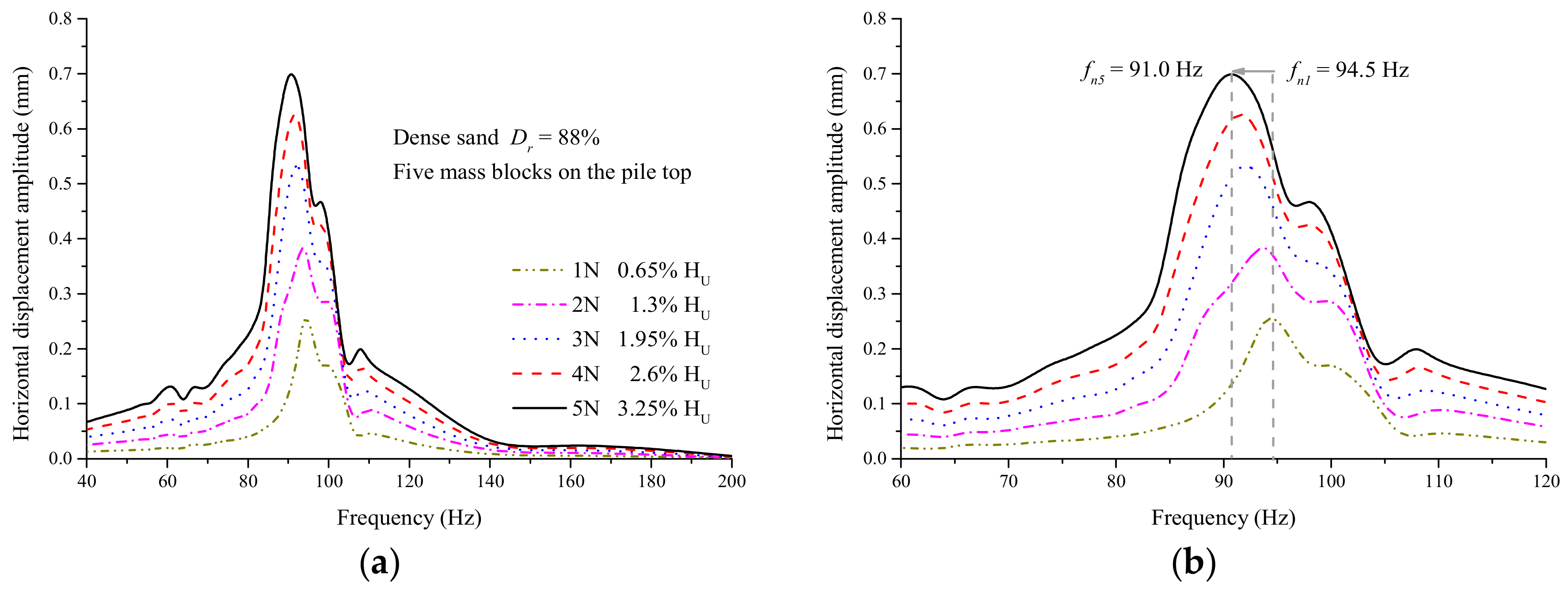
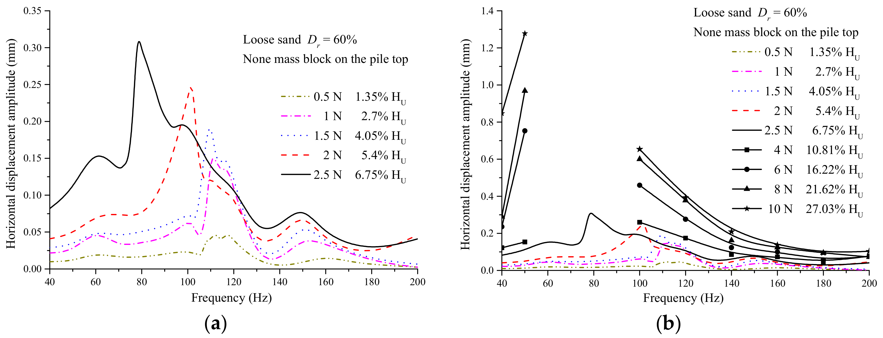
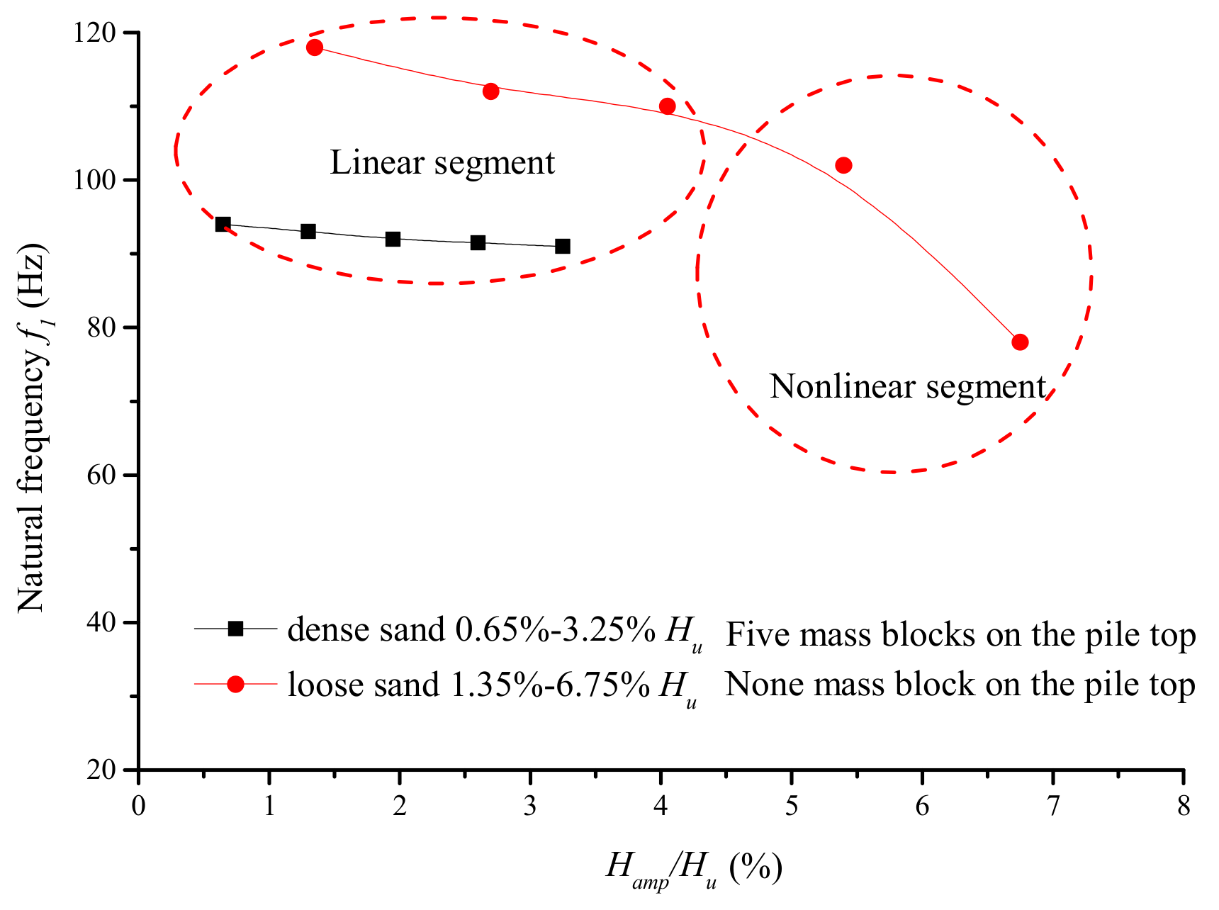
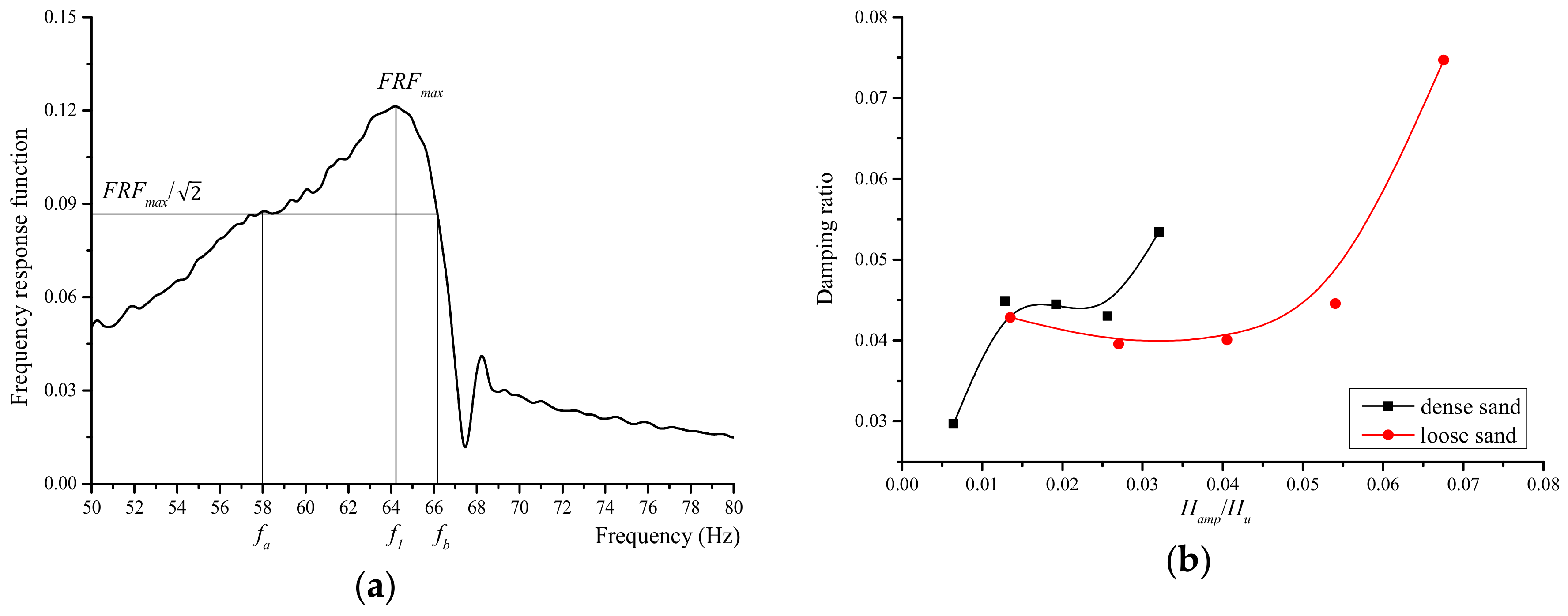
- When there is no static load, the first natural frequency f1 decreases with the increase of the amplitudes of the dynamic loads in both dense sand and loose sand cases;
- (2)
- The first natural frequency f1 increases with the increase in the lateral static load generally in both the dense and loose sand cases; Loading-unloading-reloading to the capacity process can increase the first resonance frequency of the monopile in dense sand, but this phenomenon is not observed in loose sand case;
- (3)
- The frequency responses of the monopile in the direction perpendicular to the static loading are quite different from those in the static loading direction, as soils around the monopile are under different stress conditions, and this is more obvious in the dense sand case.
5.2. Outlook
Author Contributions
Funding
Conflicts of Interest
Nomenclature
| L | embedded length of the monopile | H | horizontal static load |
| D | diameter | Hamp | harmonic load amplitude |
| Ep | elastic modulus of the monopile | Hu | ultimate bearing capacity of the pile |
| Es | elastic modulus of soil | ρs | soil density |
| h | thickness of the monopile | L0 | length of the monopile |
| G0 | initial shear modulus of soil | f | load frequency |
| e | void ratio | hf | falling distance |
| σm’ | average effective principal stress | ρL | density of loose sand |
| hs | soil depth | K | stiffness of structure |
| Dr | relative density | ξ | damping ratio |
| a0 | dimensionless frequency | FRFmax | peak of the FRF curve |
| r | radius of the monopile | f1 | first order resonance frequency |
| ω | circular frequency | fa, fb | the frequencies corresponding to FRFmax/ |
| μs | shear modulus of soil | f2 | second order resonance frequency |
References
- DNV. Offshore Standard DNV-OS-J101: Design of Offshore Wind Turbine Structures; DNV: Oslo, Norway, 2010. [Google Scholar]
- Richards, I.A.; Byrne, B.W.; Houlsby, G.T. Monopile rotation under complex cyclic lateral loading in sand. Géotechnique 2019. [Google Scholar] [CrossRef]
- Krolis, V.D.; Zwaag, G.L.V.D.; Vries, W.D. Determining the embedded pile length for large-diameter monopiles. Mar. Technol. Soc. J. 2010, 44, 24–31. [Google Scholar] [CrossRef]
- Futai, M.M.; Dong, J.; Haigh, S.K.; Madabhushi, S.P.G. Dynamic response of monopiles in sand using centrifuge modelling. Soil Dyn. Earthq. Eng. 2018, 115, 90–103. [Google Scholar] [CrossRef]
- Lombardi, D.; Bhattacharya, S.; Muir Wood, D. Dynamic soil-structure interaction of monopile supported wind turbines in cohesive soil. Soil Dyn. Earthq. Eng. 2013, 49, 165–180. [Google Scholar] [CrossRef]
- Damgaard, M.; Bayat, M.; Andersen, L.V.; Ibsen, L.B. Assessment of the dynamic behaviour of saturated soil subjected to cyclic loading from offshore monopile wind turbine foundations. Comput. Geotech. 2014, 61, 116–126. [Google Scholar] [CrossRef]
- Leblanc, C. Design of Offshore Wind Turbine Support Structures: Selected topics in the field of geotechnical engineering. Ph.D. Thesis, Aalborg University, Aalborg, Danmark, 2009. [Google Scholar]
- Dobry, R.; Gazetas, G. Dynamic response of arbitrarily shaped foundations. J. Geotech. Eng. 1986, 112, 109–135. [Google Scholar] [CrossRef]
- Novak, M.; Nogami, T. Soil-pile interaction in horizontal vibration. Earthq. Eng. Struct. D 1977, 5, 263–281. [Google Scholar] [CrossRef]
- Muki, R.; Sternberg, E. On the diffusion of an axial load from an infinite cylindrical bar embedded in an elastic medium. Int. J. Solids Struct. 1969, 5, 587–605. [Google Scholar] [CrossRef]
- Pak, R.Y.S.; Jennings, P.C. Elastodynamic response of pile under transverse excitations. J. Eng. Mech. 1987, 113, 1101–1116. [Google Scholar] [CrossRef]
- He, R.; Pak, R.Y.S.; Wang, L.Z. Elastic lateral dynamic impedance functions for a rigid cylindrical shell type foundation. Int. J. Numer. Anal. Met. 2017, 41, 508–526. [Google Scholar] [CrossRef]
- He, R.; Kaynia, A.M.; Zhang, J.S. A poroelastic solution for dynamics of laterally loaded offshore monopiles. Ocean Eng. 2019, 179, 337–350. [Google Scholar] [CrossRef]
- He, R.; Kaynia, A.M.; Zhang, J.S. Influence of vertical shear stresses due to pile-soil interaction on lateral dynamic responses for offshore monopiles. Mar. Struct. 2019, 64, 341–359. [Google Scholar] [CrossRef]
- Zdravkovic, L.; Taborda, D.M.G.; Potts, D.M.; Jardine, R.J.; Gretlund, J.S. Numerical Modelling of Large Diameter Piles under Lateral Loading for Offshore Wind Applications. In Proceedings of the International Symposium on Frontiers in Offshore Geotechnics, Oslo, Norway, 10–12 June 2015. [Google Scholar]
- Sen, R.; Davies, T.G.; Banerjee, P.K. Dynamic analysis of piles and pile groups embedded in homogeneous soils. Earthq. Eng. Struct. Dyn. 1985, 13, 53–65. [Google Scholar] [CrossRef]
- Latini, C.; Zania, V. Dynamic lateral response of suction caissons. Soil Dyn. Earthq. Eng. 2017, 100, 59–71. [Google Scholar] [CrossRef]
- Tao, W.Y.; He, R.; Zheng, J.H. Analysis on horizontal-rocking vibrations of monopile supporting wind turbine. J. Hohai Univ. Nat. Sci. 2018, 46, 260–267. [Google Scholar]
- He, R.; Ji, J.; Zhang, J.S.; Peng, W.; Sun, Z.F.; Guo, Z. Dynamic impedances of offshore rock-socketed monopiles. J. Mar. Sci. Eng. 2019, 7, 134. [Google Scholar] [CrossRef]
- Ma, H.; Yang, J.; Chen, L. Numerical analysis of the long-term performance of offshore wind turbines supported by monopiles. Ocean Eng. 2017, 136, 94–105. [Google Scholar] [CrossRef]
- Beuckelaers, W. Numerical Modelling of Laterally Loaded Piles for Offshore Wind Turbines. Ph.D. Thesis, University of Oxford, Oxford, UK, 2017. [Google Scholar]
- Goit, C.S.; Saitoh, M.; Mylonakis, G.; Kawakami, H.; Oikawa, H. Model tests on horizontal pile-to-pile interaction incorporating local non-linearity and resonance effects. Soil Dyn. Earthq. Eng. 2013, 48, 175–192. [Google Scholar] [CrossRef]
- Bhattacharya, S.; Nikitas, N.; Garnsey, J.; Alexander, N.A. Observed dynamic soil–structure interaction in scale testing of offshore wind turbine foundations. J. Soil Dyn. Earthq. Eng. 2013, 54, 47–60. [Google Scholar] [CrossRef]
- Manna, B.; Baidya, D.K. Nonlinear dynamic response of piles under horizontal excitation. J. Geotech. Geoenviron. 2010, 136, 1600–1609. [Google Scholar] [CrossRef]
- Elkasabgy, M.; El Naggar, M.H. Lateral vibration of helical and driven steel piles installed in clayey soil. J. Geotech. Geoenviron. 2018, 144, 6018009. [Google Scholar] [CrossRef]
- He, R.; Zhu, T.; Ma, B.; Tao, W.Y. Dynamic Responses of Mono-piles in the Presence of Scour Holes. In Proceedings of the China-Europe Conference on Geotechnical Engineering, Vienna, Austria, 13–16 August 2018. [Google Scholar]
- Leblanc, C.; Houlsby, G.T.; Byrne, B.W. Response of stiff piles in sand to long-term cyclic lateral loading. Géotechnique 2010, 60, 79–90. [Google Scholar] [CrossRef]
- Shirzadeh, R.; Devriendt, C.; Bidakhvidi, M.A.; Guillaume, P. Experimental and computational damping estimation of an offshore wind turbine on a monopile foundation. J. Wind Eng. Ind. Aerodyn. 2013, 120, 96–106. [Google Scholar] [CrossRef]
- Damgaard, M.; Ibsen, L.B.; Andersen, L.V.; Andersen, J.K.F. Cross-Wind modal properties of offshore wind turbines identified by full scale testing. J. Wind Eng. Ind. Aerodyn. 2013, 116, 94–108. [Google Scholar] [CrossRef]
- American Petroleum Institute. Recommended Practice for Planning, Designing and Constructing Fixed Offshore Platforms—Working Stress Design, 21st ed.; API Recommended Practice 2A-WSD (RP2A-WSD); API: Dallas, TX, USA, 2000. [Google Scholar]
- Burd, H.J.; Beuckelaers, W.J.A.P.; Byrne, B.W.; Gavin, K.; Houlsby, G.T.; Igoe, D.; Jardine, R.J.; Martin, C.M.; McAdam, R.A.; Muir Wood, A.; et al. New data analysis methods for instrumented medium-scale monopile field tests. Géotechnique 2019, 1–28. [Google Scholar] [CrossRef]
- McAdam, R.A.; Byrne, B.W.; Houlsby, G.T.; Beuckelaers, W.J.A.P.; Burd, H.J.; Gavin, K.; Igoe, D.; Jardine, R.J.; Martin, C.M.; Muir Wood, A.; et al. Monotonic laterally loaded pile testing in a dense marine sand at Dunkirk. Géotechnique 2019, 1–34. [Google Scholar] [CrossRef]
- Zdravković, L.; Taborda, D.M.G.; Potts, D.M.; Abadias, D.; Burd, H.J.; Byrne, B.W.; Gavin, K.; Houlsby, G.T.; Jardine, R.J.; Martin, C.M.; et al. Finite element modelling of laterally loaded piles in a stiff glacial clay till at Cowden. Géotechnique 2019, 1–40. [Google Scholar] [CrossRef]
- Taborda, D.M.G.; Zdravković, L.; Potts, D.M.; Burd, H.J.; Byrne, B.W.; Gavin, K.; Houlsby, G.T.; Jardine, R.J.; Liu, T.; Martin, C.M.; et al. Finite element modelling of laterally loaded piles in a dense marine sand at Dunkirk. Géotechnique 2019, 1–47. [Google Scholar] [CrossRef]
- Martin, C.M.; Randolph, M.F. Upper-Bound analysis of lateral pile capacity in cohesive soil. Géotechnique 2006, 56, 141–145. [Google Scholar] [CrossRef]
- Achmus, M.; Kuo, Y.; Abdel-Rahman, K. Behavior of monopile foundations under cyclic lateral load. Comput. Geotech. 2009, 36, 725–735. [Google Scholar] [CrossRef]
- Allotey, N.; El Naggar, M.H. A numerical study into lateral cyclic nonlinear soil-pile response. Can. Geotech. J. 2008, 45, 1268–1281. [Google Scholar] [CrossRef]
- Gerolymos, N.; Escoffier, S.; Gazetas, G.; Garnier, J. Numerical modeling of centrifuge cyclic lateral pile load experiments. Earthq. Eng. Eng. Vib. 2009, 8, 61–76. [Google Scholar] [CrossRef]
- Hong, Y.; He, B.; Wang, L.Z.; Wang, Z.; Ng, C.W.W.; Masin, D. Cyclic lateral response and failure mechanisms of semi-rigid pile in soft clay: Centrifuge tests and numerical modelling. Can. Geotech. J. 2017, 54, 2016–2356. [Google Scholar] [CrossRef]
- Hardin, B.O.; Richart, F.E. Elastic wave velocities in granular soils. J. Soil Mech. Found. Div. 1963, 89, 35–65. [Google Scholar]
- Been, K.; Jefferies, M.G. A state parameter for sands. Géotechnique 1985, 35, 99–112. [Google Scholar] [CrossRef]
- Oda, M.; Koishikawa, I.; Higuchi, T. Experimental study of anisotropic shear strength of sand by plane strain test. J. Jpn. Soc. Soil Mech. Found. Eng. 1978, 18, 25–38. [Google Scholar] [CrossRef] [Green Version]
- Hariprasad, C.; Rajashekhar, M.; Umashankar, B. Preparation of uniform sand specimens using stationary pluviation and vibratory methods. Geotechn. Geol. Eng. 2016, 34, 1909–1922. [Google Scholar] [CrossRef]
- Cuéllar, P.; Baeßler, M.; Rücker, W. Ratcheting convective cells of sand grains around offshore piles under cyclic lateral loads. Granul. Matter. 2009, 11, 379–390. [Google Scholar] [CrossRef]
- Ministry of Transport of the People’s Republic of China. Code for Pile Foundation in Port Engineering; JTJ 254-1998; Ministry of Transport of the People’s Republic of China: Beijing, China, 2001.
- Hardin, B.O.; Drnevich, V.P. Shear modulus and damping in soils: Design equations and curves. J. Soil Mech. Found. Div. 1972, 98, 667–692. [Google Scholar]
- Chopra, A.K. Dynamics of Structures: Theory and Applications to Earthquake Engineering; PEARSON: London, UK, 2014. [Google Scholar]
- Seed, H.B.; Idriss, I.M. Soil moduli and damping factors for dynamic response analysis. J. Terramech. 1972, 8, 109. [Google Scholar]
- Sørensen, S.P.H.; Brødbæk, K.T.; Møller, M.; Augustesen, A.H. Review of Laterally Loaded Monopiles Employed as the Foundation for Offshore Wind Turbines; Aalborg University: Aalborg, Denmark, 2012. [Google Scholar]


| Physical Parameters | Dimensionless Characters | Value (Dr = 10%) | Value (Dr = 88%) |
|---|---|---|---|
| Embedded depth L | L/D | 5 | 5 |
| Wall thickness of the pile h | h/D | 0.01 | 0.01 |
| Elastic modulus E | Ep/Es | 21,000 | 13,000 |
| Static load H | H/Hu | 0–1.08 | 0–1.86 |
| Harmonic load Amplitude Hamp | Hamp/Hu | 1.35–27.03% | 0.65–3.25% |
| Frequency f | 0–0.72 | 0–0.56 |
| Test Name | Dr | f (Hz) | Dimensionless Frequency a0 | Amplitude Hamp (N) | Hamp/Hu | Static Load H (N) | H/Hu |
|---|---|---|---|---|---|---|---|
| L.LBC | 10% | 0 | 0 | - | - | 0–40 | 0–1.08 |
| D.LBC | 88% | 0 | 0 | - | - | 0–165 | 0–1.06 |
| L.HL | 10% | 40–200 | 0.14–0.72 | 1/2/3/4/5 | 0.65–3.25% | 0 | 0 |
| D.HL | 88% | 40–200 | 0.11–0.56 | 0.5/1/1.5/2/2.5 | 1.35–6.75% | 0 | 0 |
| 88% | 40–50 100–200 | 0.11–0.14 0.28–0.56 | 4/6/8/10 | 10.81–27.03% | 0 | 0 | |
| L.SL | 10% | Random | Hammering | - | 0–40 | 0–1.08 | |
| D.SL | 88% | 0–290 | 0–1.86 | ||||
| L.L-U | 10% | Random | Hammering | - | 0–20 | 0–0.54 | |
| D.L-U | 88% | 0–100 | 0–0.64 | ||||
| L.S-D1 | 10% | Random | Hammering | - | 0 | 0 | |
| L.S-D2 | 10% | 8 | 0.22 | ||||
| L.S-D3 | 10% | 16 | 0.43 | ||||
| D.S-D1 | 88% | 0 | 0 | ||||
| D.S-D2 | 88% | 40 | 0.26 | ||||
| D.S-D3 | 88% | 80 | 0.51 | ||||
© 2019 by the authors. Licensee MDPI, Basel, Switzerland. This article is an open access article distributed under the terms and conditions of the Creative Commons Attribution (CC BY) license (http://creativecommons.org/licenses/by/4.0/).
Share and Cite
He, R.; Zhu, T. Model Tests on the Frequency Responses of Offshore Monopiles. J. Mar. Sci. Eng. 2019, 7, 430. https://doi.org/10.3390/jmse7120430
He R, Zhu T. Model Tests on the Frequency Responses of Offshore Monopiles. Journal of Marine Science and Engineering. 2019; 7(12):430. https://doi.org/10.3390/jmse7120430
Chicago/Turabian StyleHe, Rui, and Tao Zhu. 2019. "Model Tests on the Frequency Responses of Offshore Monopiles" Journal of Marine Science and Engineering 7, no. 12: 430. https://doi.org/10.3390/jmse7120430