Article

Phase Noise Effects on OFDM Chirp Communication Systems: Characteristics and Compensation

School of Information and Communication Engineering, University of Electronic Science and Technology of China, Chengdu 611731, China
*
Author to whom correspondence should be addressed.
Information 2024, 15(4), 221; https://doi.org/10.3390/info15040221
Submission received: 5 March 2024 / Revised: 28 March 2024 / Accepted: 3 April 2024 / Published: 14 April 2024
(This article belongs to the Section Information Systems)

Abstract

:
Orthogonal frequency-division multiplexing (OFDM) chirp waveforms are an attractive candidate to be a dual-function signal scheme for the joint radar and communication systems. OFDM chirp signals can not only be employed to transmit communication data through classic phase modulation, but also can perform radar detection by applying linear frequency modulation for subcarriers. However, the performance of the OFDM chirp communication system under the phase noise environment still remains uninvestigated. This paper tries to discuss the influence of phase noise on OFDM chirp communication systems and proposes effective phase noise estimation and compensation methods. We find that the phase noise effect on OFDM chirp communication systems consists of a common phase error (CPE) and an inter-carrier interference (ICI). If not compensated, the performance of the dual-function systems can be seriously degraded. In particular, an exact expression for the signal-plus-interference to noise ratio (SINR) for the OFDM chirp communication system is derived and some critical parameters are analyzed to exhibit the phase noise effects on system performance. Moreover, two low-complexity estimation approaches, maximum likelihood (ML) and linear minimum mean square error (LMMSE), as well as two compensation approaches, the de-correlation and cancellation algorithms, are respectively utilized to eliminate the phase noise impairment. Finally, the phase noise effects and the effectiveness of the compensation approach are verified by extensive numerical results.

1. Introduction

Orthogonal frequency division multiplexing (OFDM) signals have been widely applied in wireless communication standards such as WiFi, LTE and their adaptation for car-to-car networks IEEE 802.11.p, as well as the standardization process of 5G transmissions [1]. This is not only because they have strong robustness against fading and multipath propagation effects together with a high spectrum utilization rate, but also the data transmission rate can be further improved by combining OFDM with multiple input and multiple output (MIMO) and spatial diversity. In the radar community, OFDM signals also have attracted more and more attention due to their promising features. For one thing, the OFDM radar signals can be applied to estimate range and velocity without range–Doppler coupling, which allows for independent and unambiguous range–Doppler processing [2]. For another, compared with the single-carrier waveform, OFDM signals can offer diversities along both the time and frequency dimensions, which provides many opportunities to employ sophisticated radar processing algorithms, rather than classical time domain correlation approaches, to deliver a high resolution in the range, Doppler and angle dimensions [3]. Furthermore, OFDM signals have gained widespread attention in dual-functional systems, i.e., joint radar and communications systems, to enable them to simultaneously transmit information in parallel with radar sensing [4,5,6,7,8]. Garmatyuk et al. developed an OFDM-based radar-communications system for ultra wideband (UWB) radar systems [4]. Shi et al. [6] considered to optimize the OFDM waveform by minimizing the radar transmit power with the constraint of mutual information and minimum communication system capacity. However, multi-carrier systems tend to be highly sensitive to Doppler shift caused by moving targets as well as the phase noise introduced by local oscillators, which can make the orthogonality of subcarriers being destroyed and introduced ICI [9,10]. Additionally, OFDM signals usually have a high peak-to-average power ratio (PAPR) and thus impose high requirements on the power amplifier (PA) of the transceiver [11].
OFDM chirp waveforms were first put forward by Jung-Hyo Kim for MIMO synthetic aperture radar (SAR) imaging, aiming to solve the problem of fast variation of OFDM signal envelope [12]. The OFDM chirp waveforms utilize Linear Frequency Modulation (LFM) signal, that is chirp signal, rather than conventional rectangular pulse as the subcarriers. The chirp waveform is a large Time-Bandwidth Product signal, and it can keep a constant envelope in both the time domain and frequency domain, which can help to reduce the PAPR of multi-carrier signal. In [12], two OFDM chirp waveforms are generated by the zero interleaving and shifting of a chirp spectrum as the input sequence. To generate multiple orthogonal OFDM chirp waveforms, an effective design scheme is proposed in [13,14], which includes OFDM chirp signal design and random matrix modulation. The designed waveforms are illustrated to have constant time domain and almost constant frequency-domain modulus, large time-bandwidth product and low PAPR. Subsequently, an orthogonal chirp division multiplexing (OCDM) scheme is proposed in [15], where the discrete Fresnel transform (DFnT) is applied to realize orthogonal chirp modulation in frequency domain, just like the way of the discrete Fourier transform (DFT) in the OFDM scheme.
OFDM chirp waveform schemes are also suggested for other applications such as wireless, optical fiber and underwater acoustic communication [16,17,18,19,20]. The potential possibilities of OCDM employed in wireless communication are investigated in [21,22], which demonstrated its robustness for inter-subcarrier interference caused by guard intervals. In specific MIMO radar applications, some characteristics of OFDM chirp waveforms are proved to be superior to OFDM waveforms in [14,23]. Furthermore, OFDM chirp waveform can also exhibit a better anti-interference ability while maintaining the same spectral efficiency. Therefore, OFDM chirp waveforms are expected to be an attractive candidate for joint radar and communications systems. In [24], we designed a joint radar and communication system based on OFDM chirp waveforms with the phase modulation information embedded, and the communication-embedded OFDM chirp waveform proved to be effective in communication data transmission as well as showing a good ambiguity performance. Furthermore, Jia et al. studied the ranging and communication performance of OFDM chirp-based radar communication using the universal software radio peripheral platform [25], which demonstrated that OFDM chirp waveforms allow information transmission while the radar performs radar detection.
Owing to applying orthogonal multicarrier signals, the OFDM system is quite sensitive to phase noise that is caused by imperfect oscillators in the transceivers. Especially for the broader band applications in the fifth generation of mobile telecommunications(5G) [26], the channel band for Frequency Range 2 (FR2) is in the lower millimeter-wave bands. The sensitivity to phase noise can become more severe with the increase in modulation order and the number of subcarriers [27]. Therefore, the phase noise effects on OFDM systems and the corresponding compensation methods have been analyzed in many studies [28,29,30]. It is acknowledged that random phase noise may cause multiplicative and additive effects on the received subcarrier signal [31]. The multiplicative part affects all subcarriers in the same way within one OFDM symbol period and leads to a rotation on constellation, which is described as common phase error (CPE). The additive part results in intercarrier interference (ICI) that exhibits noise-like characteristics. The CPE can directly be estimated and compensated by using pilot symbols, as shown in [32,33,34], but such a method may not always be effective because it neglects the ICI effects. The ICI self-cancellation is presented in [35], where each symbol is transmitted using two adjacent subcarriers and then the received symbols are linearly combined to mitigate the ICI. In [29], Liu et al. propose to insert some pilot tones outside the signal spectrum to estimate the parameters of phase noise by exploiting the received pilot signals, but this scheme needs extra bandwidth and can only correct the ICI from adjacent subcarriers. In [32], a phase noise suppression algorithm is proposed to mitigate both CPE and ICI simultaneously, in which the CPE and the noise energy are estimated and applied to a minimum mean square error (MMSE) equalizer.
OFDM chirp waveforms can be implemented on practical synthetic aperture radar (SAR) systems, which usually operate in KU or X band. High-frequency applications raised higher requirements for the nonlinear devices in radio frequency (RF), the phase noise can become the main detrimental for signal degradation. Since OFDM chirp and OFDM waveform employ a distinct baseband signal as the orthogonal subcarriers, some research methods in OFDM system may not be directly applied to OFDM chirp because of the different transceiver structure. As far as we know, there are still no investigations on the performance of OFDM chirp system with the influence of phase noise. In this paper, we proceed the research on the analysis and compensation of phase noise effects in OFDM chirp communication systems. The main contributions of this paper are summarized as follows:
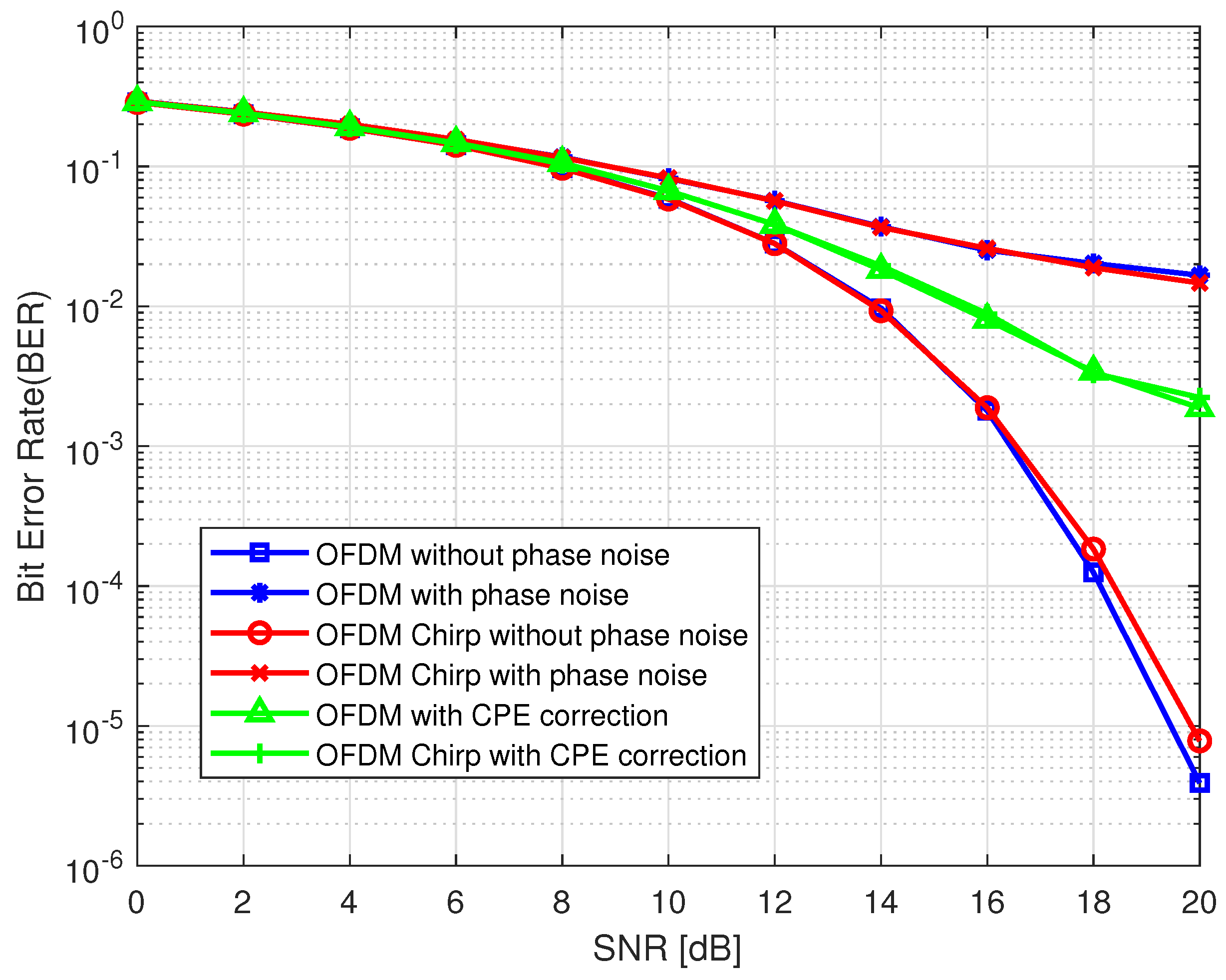
  • A mathematical model that generalizes the effects of phase noise on OFDM chirp communication systems is deduced, from which we find that the phase noise can result in common phase error (CPE) and intercarrier interference (ICI) in the OFDM chirp communication system, just like that of the OFDM communication system.
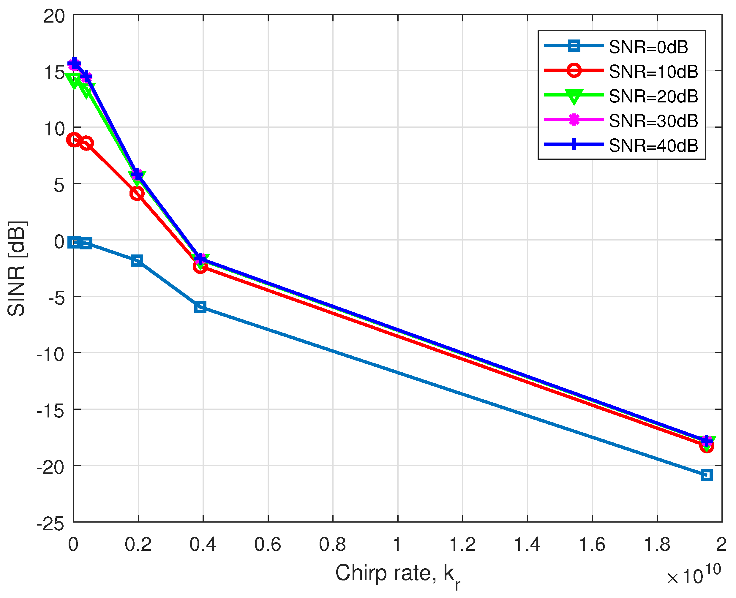
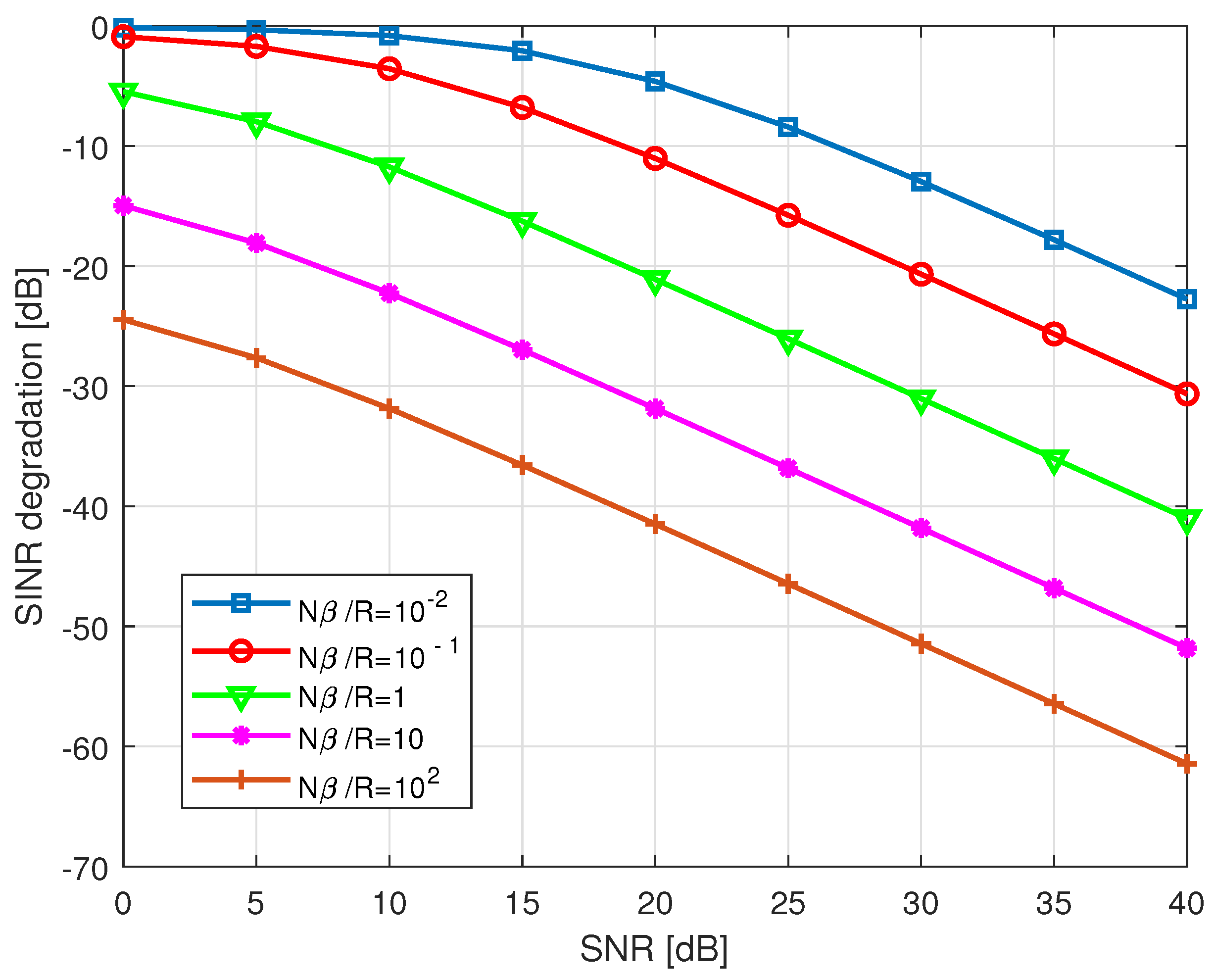
  • An exact closed-form expression for the signal-plus-interference-to-noise ratio (SINR) in the OFDM chirp communication system is derived and some critical parameters are analyzed.
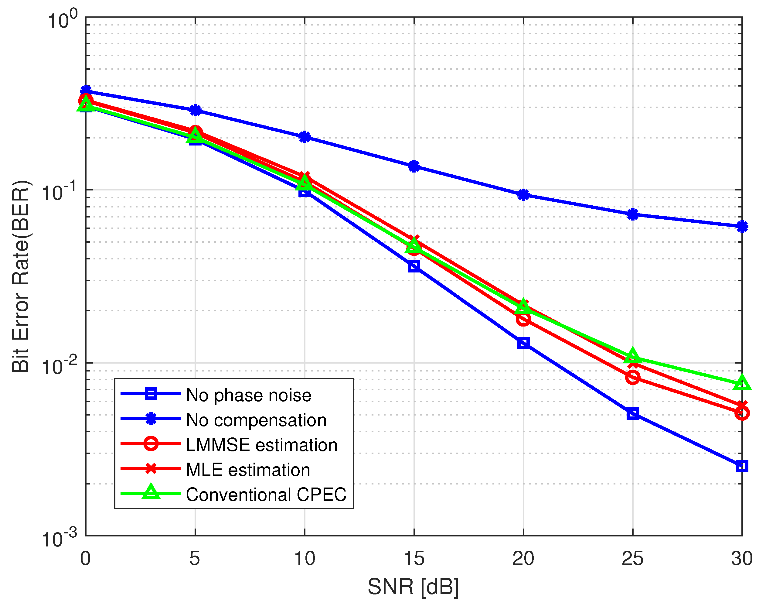
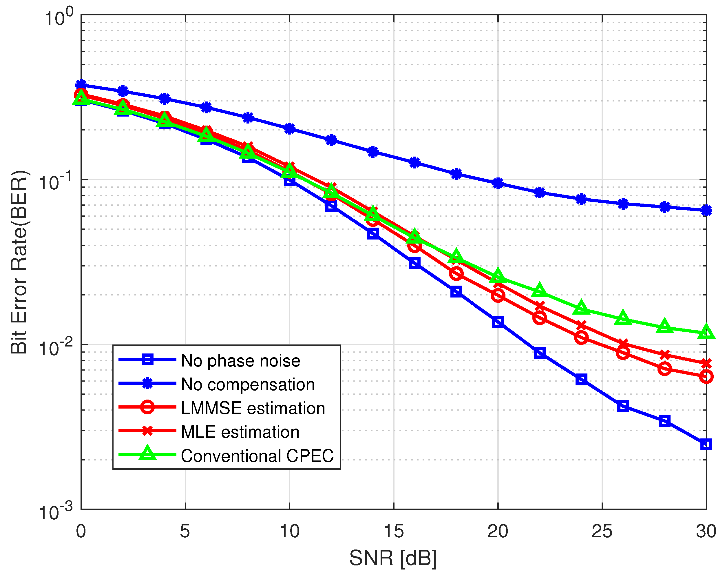
  • Two common estimation approaches, maximum likelihood (ML) and linear minimum mean square error (LMMSE), are applied to estimate the phase noise. Then, based on the phase noise estimation, we further adopt decorrelation and cancellation algorithms to compensate the phase noise impairment.
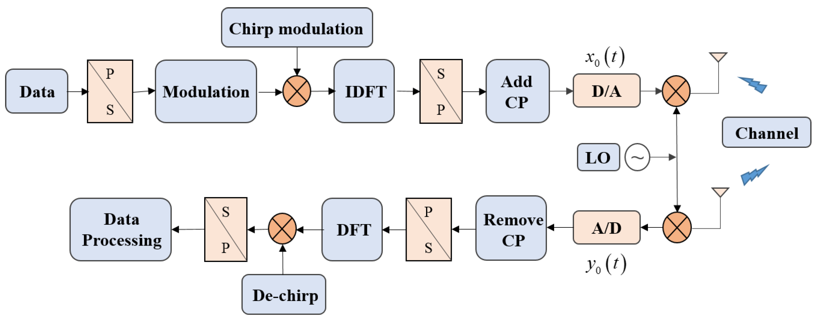
The rest of the sections of this paper are organized as follows. In Section 2, a discrete phase noise model is presented at first. Then, the OFDM chirp communication system model and signal model with phase noise effects are discussed. The closed form SINR is provided in Section 3 for system performance analysis. In Section 4, the estimation and compensation approaches for CPE and ICI mitigation are formulated. In Section 5, numerical results are given to illustrate the phase noise effect on the OFDM chirp communication system. Finally, the paper is concluded in Section 6.

2. System Model

In this section, we firstly introduce the theoretical models of phase noise and the OFDM chirp signal. Then, the OFDM chirp communication system model impaired by phase noise is presented. For simplicity, perfect frequency and timing synchronization in the system is assumed to be completed, and the transmitted signals, channel response and phase noise are all considered to be independent from each other.

2.1. Phase Noise Model

The phase noise, generated by the local oscillator (LO) both in the transmitter and receiver, may cause random phase modulation on the output carrier frequency. The distribution of the random phase noise depends on the oscillator type. Without loss of generality, we describe the phase noise as a zero-mean, non-stationary Wiener process, which is suitable for free-running oscillators. In this case, the phase noise ϕ n can be modeled as
ϕ n = ϕ n 1 + u n ,
where u n is modeled as Gaussian random variable with zero mean and variance σ u 2 = 2 π β T / N = 2 π β / R s , T is the symbol duration, N is the number of subcarriers, R s = N / T denotes the sampling rate, and β is the two-sided 3dB bandwidth of the Lorentzian power spectral density function, namely, the phase noise line width. In fact, the phase noise ϕ n is a Gaussian process with zero mean and the variance is
E ϕ n ϕ * m = σ u 2 m i n { m , n } .
Hence, it is a nonstationary random process. However, the complex oscillator output a n = e j ϕ n is a zero mean, stationary process, of which the time domain correlation function can be given by [36]
E a n a * m = e π β m n T s .

2.2. OFDM Chirp Communication Signal Model

OFDM chirp signals are initially designed by combining the OFDM principle with chirp waveforms to solve the fast variation of signal envelope in radar applications. Generally, several OFDM chirp waveforms can be designed by zero interleaving and shifting of a single chirp spectrum to produce the nonoverlapping spectra. Since it is validated that the chirp signals with adjacent starting frequencies and inverse chirp rate or nonoverlapping frequency bands can provide a good cross-correlational suppression [37], there is a more practical solution to generate multiple OFDM chirp waveforms by employing random matrix modulation in [13,14]. Basically, the premise of all these waveform design schemes is to maintain the orthogonality of the subcarriers. Suppose an existing OFDM chirp waveform consists of N subchirps, the mth symbol can be represented by [13]
u m t = n = 0 N 1 b m , n e j 2 π c m , n Δ f t + j π k r t 2 r e c t t n T b T b ,
where b m , n is the subchirp amplitude, c m , n is the subcarrier frequency index. k r is the subchirp rate and T b is the subchirp duration. r e c t denotes the rectangular impulse response. The subchirp starting frequency is determined by c m , n Δ f .
Accordingly, the cross-correlation function between any two subchirps during each pulse duration can be expressed as
1 T b 0 T b e j 2 π c m , n Δ f t + j π k r t 2 e j 2 π c m , n Δ f t + j π k r t 2 * d t = sinc π c m , n c m , n Δ f T b ,
where * denotes the conjugate operator. Hence, when Δ f satisfies Δ f = k T b , k = 1 , 2 , , where k is an arbitrary integer, sinc π c m , n c m , n Δ f T b = 0 . That is, the two subchirps can be time orthogonal.
We extend the OFDM chirp waveform by embedding communication information, among which, the communication-embedded OFDM chirp waveform can be regarded as a parallel stream of multiple chirp signals with orthogonal subcarriers, each modulated with different transmit data symbols [24]. Considering a communication-embedded OFDM chirp waveform with N subcarriers, a baseband OFDM chirp pulse is given by
x m t = k = 0 N 1 X m k e j 2 π k Δ f t + j π k r t 2 r e c t t m T T ,
where T is the symbol duration, Δ f = 1 T is the frequency spacing of subcarriers. X m k k = 0 N 1 denote the transmitted information in frequency domain which can be obtained using some demodulation scheme in communication. The subscript m is the individual OFDM chirp symbol index. Therefore, the corresponding discrete OFDM chirp waveform on the nth sample of the mth symbol can be written as
x m n = k = 0 N 1 X m k e j 2 π k n N + j π k r n T s 2 = k = 0 N 1 X m k e j 2 π k n N + j π B c T s n 2 N ,
where e j π k r n T s 2 is the discrete chirp signal and k r = B c N T s denotes the sub-chirp rate, B c is the bandwidth of the sub-chirps, T s is sampling interval. The above equation is a discrete baseband signal of communication-embedded OFDM chirp signal, which facilitates the subsequent analysis of phase noise effect.

2.3. OFDM Chirp Communication System with Phase Noise

Before studying the effect of phase noise on OFDM chirp communication system, we should have a specific notion of the basic implementation process of the system. Owing to the similarity of the structure of the OFDM signal and OFDM chirp signal, the modulation and demodulation scheme can be implemented in a similar manner as a conventional OFDM communication system.
The block scheme of the OFDM chirp communication system architecture is illustrated in Figure 1. Firstly, the communication data bits are divided into parallel streams via serial-to-parallel (S/P) conversion, and mapped into complex modulation symbol sequences according to different modulation schemes [24]. We can notice that the main implementation difference between OFDM chirp system and standard OFDM methods in system schemes is that the former has a chirp modulation before inverse discrete Fourier transform (IDFT) to control the spectrum of subcarriers, whereas the latter utilizes sinusoid signal as the carriers, which can be directly achieved by IDFT and RF processing. In addition, the chirp modulation can also be performed in time domain after IDFT or in RF processing, due to the fact that the orthogonal chirp subcarriers can be generated by surface acoustic wave (SAW) in the filtering approach or by a voltage-controlled oscillator (VCO) in the frequency modulation approach [38]. Next, a block-wise IDFT and a subsequent parallel-to-serial conversion was carried out. These frames are then converted into analog signals after adding cyclic prefix and mixed with local oscillator, so that the signal can radiate on the carrier frequency. In the receiver, the same steps are carried out in an inverse order. After removing the cyclic prefix and an fast Fourier transform (FFT), the received modulation symbols can be recovered from the baseband signal by a de-chirp operation.
In communication-embedded OFDM chirp transceiver system, after down conversion, analog-to-digital conversion and removing CP, the received symbols affected by phase noise can be expressed as
y m n = x m n e j ϕ T x , m n h m n + z m n e j ϕ R x , m n = x m n e j ϕ T x , m n F 1 H m k + z m n e j ϕ R x , m n
where ⊗ and F 1 denote the circular convolution and Inverse Fourier transform, ϕ T x , m and ϕ R x , m are the phase noise generated by the LO of transmitter and receiver, respectively, while z m n is the additive white Gaussian noise (AWGN) with zero mean and variance σ z 2 , z m n and H m k k = 0 N 1 , respectively, denote the channel coefficients in the time and frequency domains, which are assumed to be known in the following sections. Without loss of generality, we assume that the transmitted OFDM chirp signals propagate through a multi-path and slow fading channel, whose response does not vary within an OFDM chirp symbol [39], and the average power of the channel response was normalized to unity, that is, E [ H m k 2 ] = 1 .
To investigate how the phase noise affect the received OFDM chirp symbols, we first make a transformation of Equation (8) to the frequency domain by DFT, which yields
Y m k = X m k H m k P m k + Z m k = X m k H m k P m 0 + IC I m ( k ) + Z m k .
The detailed derivation is shown in Appendix A. Wherein, Y m k and Z m k denote the received signals and noise in frequency domain. The term X m k H m k P m 0 represents common phase error (CPE) and IC I m ( k ) was known as intercarrier interference (ICI). It is shown that the amplitude of the desired subcarrier is attenuated and the phase is rotated due to the phase noise effect. Moreover, the ICI from the other subcarriers can be considered as an additional noise, and as a consequence, the SNR of the received signal would be decreased. Respectively, the IC I m ( k ) and P m ( k ) are denoted as
IC I m ( k ) = r = 0 , r k N 1 X m r H m r P m k r ,
and
P m k = 1 N n = 0 N 1 e j 2 π k n N e j π B c T s n 2 N e j ϕ m n .
where ϕ m n = ϕ T x , m n ϕ R x , m n denotes the total phase noise in transmitter and receiver of the OFDM chirp communication system, P m k is the random phase rotation. However, as we have seen, this counterpart in the conventional OFDM communication system is given by [30]
P m k = 1 N n = 0 N 1 e j 2 π k n N e j ϕ m n .
We can notice that the difference between (11) and (12) lies in the product factor e j π B c T s n 2 N in Equation (11). Meanwhile, two conclusions can be inferred:
(1): As shown in the first term of Equation (9), the received symbols suffer from a CPE, which results in a common phase rotation by P m 0 on the constellation. This is similar to OFDM, but the size of the rotation angle can be different.
(2): The impact of ICI on the OFDM Chirp received symbols is quite different from that of the OFDM received symbols, because P m k and I m k have different statistical properties.

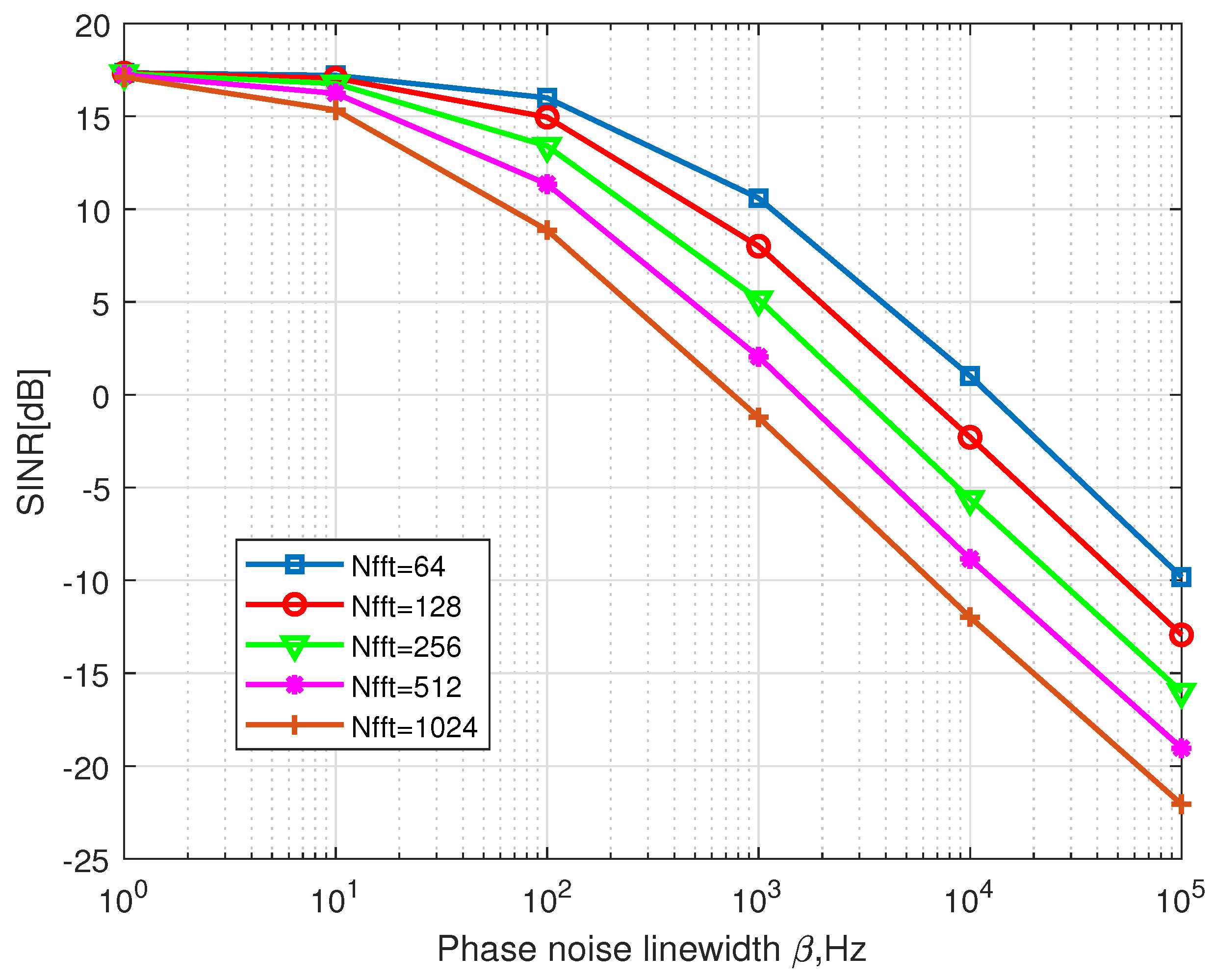
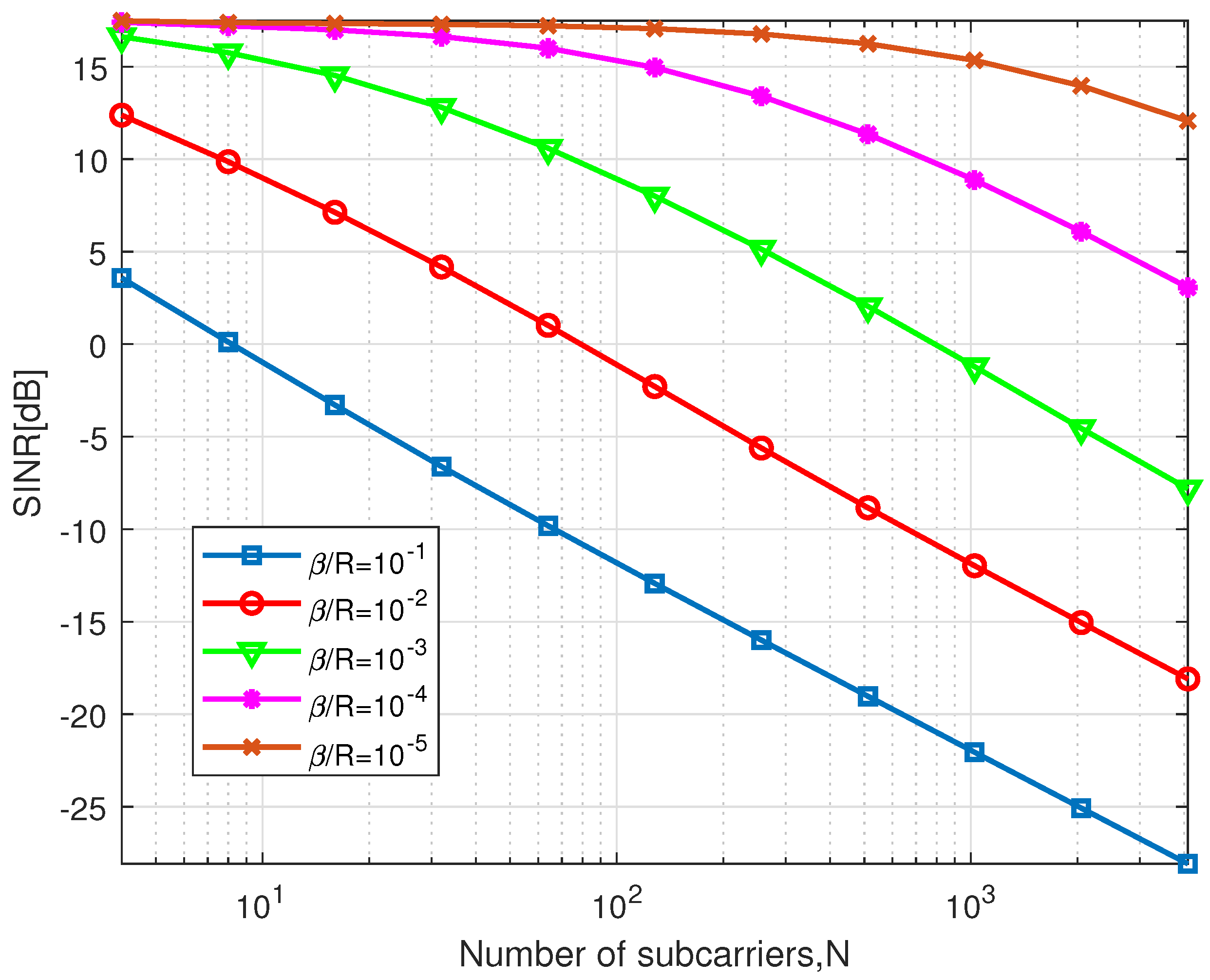
3. Exact SINR Expression

SINR is an important indicator of system performance, an exact and closed-form expression of SINR can provide an insight into phase noise effects on the actual systems by introducing it as a function of critical system parameters [30]. In particular, a thorough and accurate analysis can help to determine an acceptable level of phase noise and how to design the system to avoid severe degradation in the presence of phase noise. In addition, as far as we know, the phase noise effects on OFDM chirp communication system performance have not been studied extensively in the existing literatures. Hence, in this section, we try to make a detailed derivation of the exact SINR expression.
Generally, the transmitted signals are assumed to be independent and the mean power is E [ X m k 2 ] = E s . According to Equation (9), the SINR of the mth received symbol after DFT can be expressed as
Γ = E s E P m 0 2 E IC I m ( k ) 2 + E Z m k 2 .
in which the channel energy satisfies the normalization condition E [ H m k 2 ] = 1 . Due to the mutual independence of different signals, according to Equation (10), we can obtain
E IC I m ( k ) 2 = E s r = 0 , r k N 1 E P m r 2 .
It is noted that SINR expression has a similar form to that of the OFDM system on the condition of AWGN channels in [32], the main difference lies in the term P m ( r ) . If the transmitted signals are independent and channel energy on each subcarrier is unity, the energy of P m ( r ) in OFDM chirp communication system can be calculated as (see Appendix B)
E P m r 2 = 1 N 2 2 d r N + 1 N + 1 d r + N d r 1 2 N
where · indicates the real part of a complex variable. Wherein, the critical item d r is
d r = e j π B c T s 1 N e j 2 π r N e π β R ,
where R = N / T denotes the transmission data rate, T is the symbol duration. Equation (15) shows the dependence of the energy of P m ( r ) on the time-bandwidth product of sub-chirps, phase noise line width β , number of subcarriers N, and transmission data rate R. Substituting Equation (15) into Equation (14) yields
σ I C I 2 = E IC I m ( k ) 2 = E s N 2 r = 1 N 1 2 d r N + 1 N + 1 d r + N d r 1 2 N
Finally, we can substitute (15) and (17) into (13), and then, the exact SINR expression is calculated as
Γ = 2 d 0 N + 1 N + 1 d 0 + N d 0 1 2 N r = 1 N 1 2 d r N + 1 N + 1 d r + N d r 1 2 N + N 2 γ s
where γ s = E s / σ z 2 denotes the signal-to-noise ratio (SNR). It is indicated that, in the presence of phase noise, several parameters would affect the performance of OFDM chirp communication system, which results in serious performance degradation that is unacceptable in practical applications.

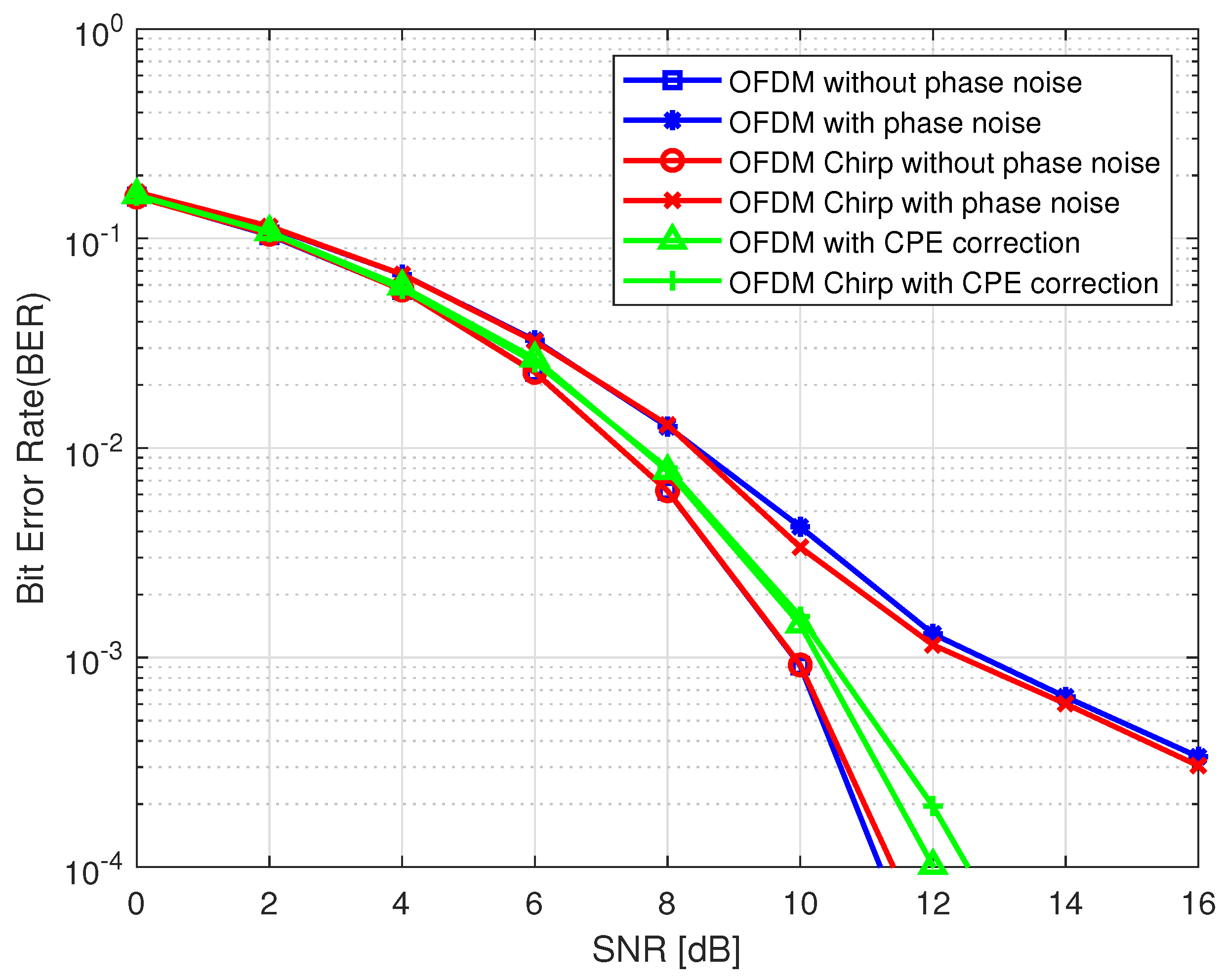
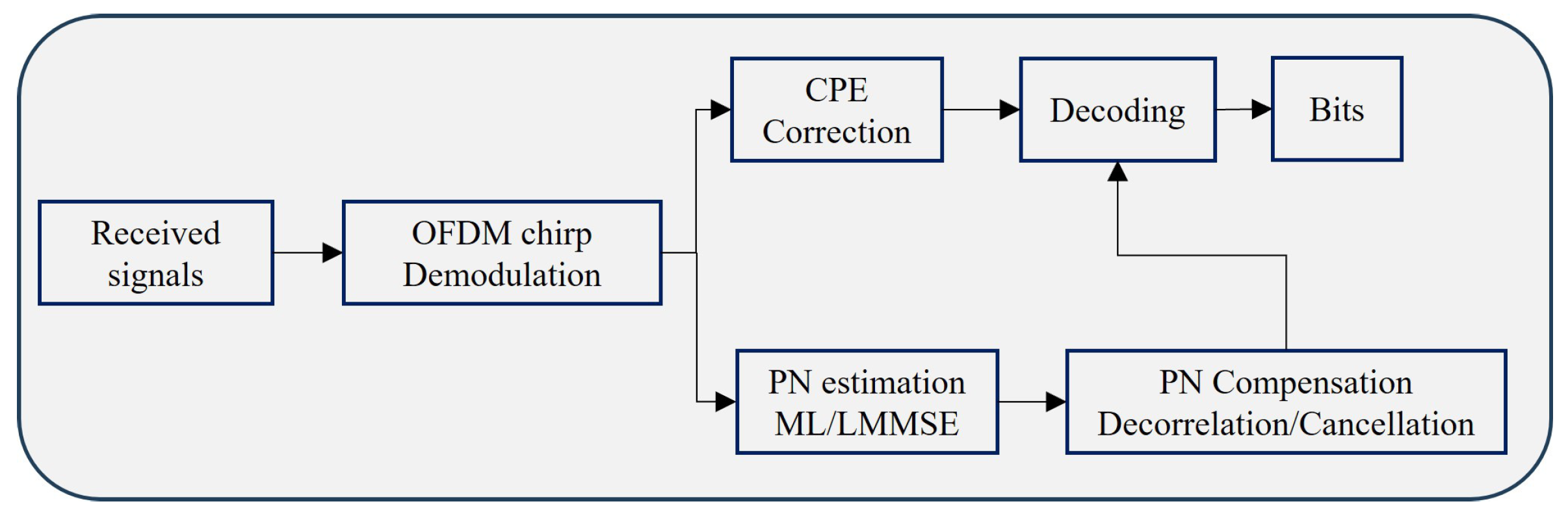
4. Phase Noise Mitigation

The effects of phase noise on the OFDM chirp communication system can be divided into CPE and ICI, which is analogous to that of OFDM system. For a conventional OFDM communication system, the classic method to compensate the phase noise is to extract the phase difference from the pilot signal. It is is also applicable to the OFDM chirp signal. For brevity, we rewrite Equation (9) as
Y m k = X m k H m k P m 0 + Z ˜ m k
where Z ˜ m k represents the sum of ICI introduced by both of the phase noise and the channel noise. It is noticed that the CPE term stays invariant within an OFDM chirp symbol. Hence, it can be estimated using a preamble or pilot symbols [32]. To estimate P m 0 in the CPE term, we can obtain the minimum value of the cost function
k X p Y m k X m k H m k P m 0 2
that is,
P ^ m 0 = arg min P m 0 k X p Y m k X m k H m k P m 0 2 = Y m k X m * k H m * k k X p X m k H m k 2
where X p stands for the set of pilot signals. The channel estimation for a traditional OFDM communication system has been considered in many papers [39,40]. Therefore, when considering the analysis of phase noise effect, the channel frequency response H m k k = 0 N 1 can be assumed to be known.
By simply utilizing zero-forcing (ZF) equalization, we can obtain P ^ m 0 according to Equation (20), and then, the transmitted data symbols can be estimated by
X ^ m k = H m 1 k P ^ m 1 0 Y m k .

4.1. Phase Noise Estimation

The tracking of CPE mainly involves how to reduce the estimated noise variance and the CPE estimation problem in multi-path channels. The ICI effects resembles thermal noise, which is hard to detect and estimate. In order to further mitigate the phase noise effect on the OFDM chirp communication system, in this subsection, we try to employ the similar way to that of the OFDM system to suppress both CPE and ICI in the meantime. Firstly, we can rewrite the received symbols in Equation (9) into a matrix form
Y = W ^ p + Z = w ^ 0 w ^ N 1 w ^ 1 w ^ 1 w ^ 0 w ^ 2 w ^ N 1 w ^ N 2 w ^ 0 p 0 p 1 p N 1 + Z 0 Z 1 Z N 1
where Y = Y 0 , Y 1 , , Y N 1 T and Z = Z 0 , Z 1 , , Z N 1 T , W ^ includes the frequency-domain transmitted signal and the channel frequency response, among which, w ^ k = H k X ^ k , k = 0 , 1 , , N 1 . It is noted that W ^ is a block circulant matrix, each row of W ^ has the identical elements as the previous row, but moved one position to the right and wrapped around; hence, it is usually nonsingular in practice. Then, the phase noise vector p can be estimated by the following ML estimation
p ^ = arg min p Y W ^ p } 2 ,
which leads to
p ^ m l = W ^ H W ^ 1 W ^ H Y = W ^ 1 Y .
Typically, this estimation technique is applied to simultaneously suppress CPE and ICI. The computational complexity can be significantly reduced due to the circulant matrix structure of W ^ . Another frequently used approach is the linear minimum mean square error estimation (LMMSE). Based on the received signal matrix in (23), the phase noise vector p can be estimated by
p ^ l m m s e = R pY R Y 1 Y ,
where
R pY = E [ p Y H ] = R p W ^ H ,
and
R Y = E [ Y Y H ] = W ^ R p W ^ H + σ z 2 I .
in which R p = E [ p p H ] = e π β m n T s is the frequency domain phase noise correlation matrix mentioned before, and β is phase noise line width. Substituting (26) and (27) into (25) yields
p ^ l m m s e = R p [ R p + σ z 2 ( W ^ H W ^ ) 1 ] 1 W ^ 1 Y .
From the above equation, we can see that LMMSE method is influenced by the phase noise line width β and the AWGN noise variance σ z 2 .

4.2. Phase Noise Compensation

The CPE term for all OFDM chirp subcarriers is the same, and it is rather easy to compensate it using some common estimation methods. However, the ICI term is random and varies for different subcarriers, making it difficult to eliminate. As discussed above, both of ML and LMMSE methods can be employed to estimate phase noise parameters. In this subsection, we try to adopt two approaches for the phase noise compensation, de-correlation and ICI cancellation, which are commonly utilized to deal with the phase noise in OFDM systems.
As described in Section 4.1, the phase noise estimated value p ^ k k = 0 N 1 can be obtained. The phase deviation varies between different subcarriers, which means that we must continuously estimate and compensate for the phase noise effect over time. In fact, the received symbols in Equation (23) can be rewritten as
Y = P ^ w + Z = p ^ 0 p ^ 1 p ^ N 1 p ^ N 1 p ^ 0 p ^ N 2 p ^ 1 p ^ 2 p ^ 0 w 0 w 1 w N 1 + z 0 z 1 z N 1 .
Likewise, P ^ is a block circulant matrix as well, each row has the identical elements as the previous row, but moved one position to the right and wrapped around. In this case, w = HX , with Y = Y 0 , Y 1 , , Y N 1 T and H = d i a g h 0 , h 1 , , h N 1 . Once p ^ k k = 0 N 1 is obtained, after phase noise estimation and ZF equalization, we can obtain the estimated data
X ^ = H 1 P ^ 1 Y .
This is the de-correlation approach which is often used for phase noise compensation. In general, the circulant matrix P ^ can be diagonalized by
P ^ 1 = F H Λ 1 F ,
where F is the DFT matrix denoted by
F = 1 N 1 1 1 1 e j 2 π N e j 2 π N 1 N 1 e j 2 π N 1 N e j 2 π N 1 2 N ,
and the diagonal elements of Λ are the IDFT of p k in frequency domain. Then, based on the phase noise expression in (11), the nth item in the diagonal matrix Λ can be given by
Λ n = k = 0 N 1 p ^ k e j 2 π k n N = e j π B c T s n 2 N + ϕ m n
Finally, the estimated data after phase noise compensation can be expressed as
X ^ = H 1 F H Λ 1 FY .
It is noted that the estimation of X ^ depends on the diagonal matrix operations and DFT transforms, and thus the computational complexity can be greatly reduced.
From (35), we can see that the de-correlation approach to phase noise compensation still requires the calculation of the inverse of a matrix. The cancellation method can avoid the operation of matrix inversion. Firstly, we can rewrite (30) in the following form
Y = p ^ 0 HX + W ^ ( 1 ) P ^ ( 1 ) + Z ,
where p ^ 0 is the CPE factor which can be obtained by ML estimation. The matrix W ^ ( 1 ) equals to the matrix W ^ in (23) with the first column deleted. Wherein, P ^ ( 1 ) is equal to the estimation of vector P in (23) with the first sub-vector removed. Then, after ZF equalization, the estimated data can be given by
X ^ = H 1 p ^ 0 1 Y W ^ ( 1 ) P ^ ( 1 ) .
Compared with the de-correlation approach, the ICI and CPE cancellation method can reduce computational complexity in further, because it does not need to calculate the matrix inversion.

4.3. Computational Complexity Analysis

The block diagram of OFDM chirp receiver with phase noise estimation and compensation is shown in Figure 2. The phase noise mitigation can be carried out either by CPE correction only or simultaneously CPE and ICI suppression. While the latter should firstly estimate the phase noise utilizing ML and LMMSE, and then the de-correlation or cancellation approach can be applied to compensate the phase noise effect.
The ML estimation approach need to calculate the inversion of W ^ , the computation is of the order of O N 3 . By introducing the P ^ which can be factorized into three matrices with one being diagonal and the other two being unitary. The approximate numbers of complex multiplications and complex additions for F H Λ 1 FY can be 3 N 2 and 3 N 2 2 N . Since F is DFT matrix that can be implemented by fast algorithm, the complex multiplications and complex additions can be reduced into ( 3 N log 2 N + N ) / 2 and 3 N log 2 N . From (29),we can see that LMMSE is much more complex than ML, because it requires the additional computation of R p R p + σ z 2 W H W 1 1 . The computational complexity for the cancellation method for p ^ 0 1 Y W ^ ( 1 ) P ^ ( 1 ) in Equation (37) should be 2 N complex multiplications and 2 N 1 complex additions.

5. Numerical Results

In this section, the effect of phase noise on the OFDM chirp communication system is discussed and analyzed. we first investigate some parameters that may affect the SINR performance of the system. Then, the proposed phase noise estimation and compensation techniques are verified by comparing and analyzing the BER performance of the OFDM chirp communication system.

5.1. SINR Analysis

The exact SINR expression is deduced in Section 3, we can see from the results that SINR is a function of various system parameters β , N , k r , T s , R , γ s , and some ratios associated with them. During the simulation, some parameters are set to be fixed values while other parameters change. Herein, the number of subcarriers is set to N = 256 with a cyclic prefix of length 32 guard-band subcarriers. The sample duration T s = 1 × 10 6 s and the transmission data rate R = 10 6 samples/s. The default chirp rate is k r = 2 × 10 9 . The phase noise is 3 dB and the line width is β = 50 Hz. The numerical results of SINR are depicted in Figure 3, Figure 4, Figure 5 and Figure 6.
There is no doubt that the phase noise line width can influence the OFDM chirp communication system for the sake of imperfect oscillators. As shown in Figure 3, the larger the line width of β , the worse the SINR performance. When β > 10 2 , SINR is degrading as a logarithmically function of phase noise line width, which is the same as that in OFDM system. Meanwhile, the SINR level becomes lower with the increase in subcarrier numbers. In particular, the average SINR is almost 10 dB lower than that of the OFDM system. This problem can be resolved by improving oscillator accuracy or modifying the generation mechanism of the OFDM chirp waveform.
From Figure 4 we can see that the SINR level decreased with the increasing in N, which can be interpreted as the larger number of subcarriers and the shorter subcarrier spacing distance. For this reason, the system would be more sensitive to phase noise. When β / R ratio is of the order of magnitude of 10 2 or even more, doubling N always causes an approximate 3 dB loss in SINR. It is also apparent that when the β / R ratio becomes lower, SINR is gradually less affected by the number of subcarriers.
Figure 5 illustrates how the chirp rate k r affects the SINR performance with SNR varies. To controlling variables, we set the symbol duration T and the number of subchirps N as constant. That is, the chirp rates k r are improved when the bandwidth of the chirp subcarrier B c is increased. We can see from Figure 5 that the higher chirp rate, the lower SINR level. However, it also reveals a fact that the bandwidth of the chirp subcarrier has a maximum limitation. In this simulation, the maximum subcarrier chip rate k r = 3 × 10 9 and SNR should be greater than 10 dB. Furthermore, as can be seen from Figure 5, the SINR performance can not increase with SNR when SNR > 30 dB.
Figure 6 depicts the relationship between SINR degradation and SNR with the change of 3 dB in normalized bandwidth N β / R . When 10 2 < N β / R < 1 , the phase noise is slowly varying type during an OFDM chirp symbol and the CPE becomes dominant. We can note that SINR degrades by 22 dB for N β / R = 10 1 when the SNR equals 30 dB, which is still a pretty high system loss. Therefore, effective schemes for phase noise correction should be applied. However, for high phase noise levels with N β / R 1 , the phase noise varies rapidly during an OFDM chirp symbol and ICI dominates over the CPE. In Figure 6, SINR degradation exceeds the value of SNR itself, which implies that the ICI overwhelms the desired signals. The phase noise correction schemes based on CPE estimation are not available any more. Hence, simultaneous CPE and ICI correction should be considered to mitigate the phase noise effect.

5.2. Phase Noise Mitigation

The phase noise compensation scheme is simulated for Rayleigh fading channels by Monte Carlo simulations. As mentioned before, the channel information was assumed known in the receiver. The simulation parameters are chosen by referring OFDM system in IEEE 802.11a standard [41], the number of subcarriers is N = 64 , the total number of pilots is set to N p = 8 . The channel model is a Rayleigh fading channel with N t a p = 2 delay taps, and the channel coefficients are also normalized. The bits are generated randomly, There are respectively 128 and 256 bits in a single OFDM chirp block for QPSK and 16QAM. To improve the accuracy of estimation and compensation, we assume a prior knowledge of AWGN and phase noise statistics are available.
Figure 7 and Figure 8 compares the BER performance versus SNR for both OFDM chirp system and OFDM system when QPSK and 16QAM modulated scheme are employed. The no phase noise and no compensation results are compared with the scheme using CPE estimation only. The CPE estimation is carried out in the frequency domain using the classic method based on pilot tones. It can be seen from these two figures that the BER performance of the OFDM chirp system and OFDM system are similar, but the OFDM system performs a little better than the OFDM chirp system. The CPE estimation and correction help improve the system performance, but it has a lower error limit at high SNR due to the fact that it does not consider ICI correction.
Figure 9 and Figure 10 illustrate the performance of ZF equalization with ML and LMMSE phase noise estimations, respectively. The phase noise variance is defined as ρ = β T = 10 2 . From the results, we can see that both the ML and LMMSE approaches can achieve satisfactory estimation performance. For sufficiently high SNRs, there is a performance gain of about 2 dB for the LMMSE approach, which can be observed in comparison with MLE approach. The reason for this gain lies in that the LMMSE utilizes the statistical characteristics of phase noise to minimize the overall estimation errors. While for low SNRs (less than 10 dB), the AWGN noise comes to be dominant, the performance with or without phase noise is indistinguishable, and none of mitigation methods affect the performance significantly. The phase noise mitigation performance of the decorrelator and the interference canceler seem to parallel very closely, only the ICI cancellation can achieve lower computational complexity. The conventional CPE compensation technique was simulated for comparison, and it is clear that the performance of MLE and LMMSE approaches outperformed the CPE compensation method for both the decorrelator and the interference canceler cases.

6. Conclusions

In this paper, the effects of phase noise on the OFDM chirp communiation system performance have been analyzed. OFDM chirp waveform is quite sensitive to phase noise just like the OFDM system, which gives rise to CPE and ICI, and leads to performance loss. Some approaches were proposed in the literature to mitigate phase noise in the frequency domain by evaluating and compensating CPE and ICI. Firstly, we introduced a mathematical model to reveal the effects of phase noise in OFDM chirp communication system. Then, an exact closed-form expression for the SINR was derived and the critical parameters were analyzed. In the presence of phase noise, the quantitative relations of critical parameters to system performance, such as phase noise line width, number of subcarriers, chirp rate, sample duration, transmission data rate and SNR, have been presented by means of mathematical functions. We find that random phase noise in OFDM chirp communication system also can lead to CPE and ICI the same as conventional OFDM system.
The BER performance for OFDM chirp communication system and OFDM system was compared, and the CPE compensation approaches based on pilots tones were simulated as well. In most cases, the OFDM chirp communication system was inclined to be more susceptible to phase noise than OFDM system even when using low-order modulation. Furthermore, both MLE and LMMSE algorithms were presented to estimate phase noise, and the phase noise was compensated by decorrelation and cancellation algorithms based on the obtained estimations. The two approaches were proved to have similar performance in mitigating phase noise. The ML and LMMSE methods were used to estimate the phase noise in the OFDM chirp communication system. Both of the two approaches were proved to be effective, but LMMSE could perform better than ML. However, ML is a much more simple yet effective way to estimate and mitigate phase noise.

Author Contributions

Conceptualization, W.W.; Methodology, M.L. and W.W.; Validation, M.L.; Investigation, M.L.; Writing—original draft, M.L.; Supervision, W.W.; Project administration, W.W. All authors have read and agreed to the published version of the manuscript.

Funding

This research received no external funding.

Institutional Review Board Statement

Not applicable.

Informed Consent Statement

Not applicable.

Data Availability Statement

The data presented in this study are available on request from the corresponding author.

Conflicts of Interest

The authors declare no conflicts of interest.

Appendix A. Received Symbols after DFT

In order to reveal the influence of phase noise on OFDM chirp signal in frequency domain, the received symbols after DFT were written as
Y m k = 1 N n = 0 N 1 x m n e j ϕ T x , m n F 1 H m k + z m n e j ϕ R x , m n e j 2 π k n N = 1 N n = 0 N 1 x m n F 1 H m k e j ϕ m n e j 2 π k n N + 1 N n = 0 N 1 z m n e j ϕ R x , m n e j 2 π k n N = r = 0 N 1 X m r H m r 1 N n = 0 N 1 e j 2 π k r n N + j π B c T s n 2 N e j ϕ m n + Z m k = r = 0 N 1 X m r H m r P m k r + Z m k = X m k H m k P m k + Z m k
where ϕ T x , m n and ϕ R x , m n are the phase noise generated by local oscillator of transmitter and receiver, respectively. ϕ m n = ϕ T x , m n ϕ R x , m n is the total system phase noise.

Appendix B. Energy of Pm(r)

It is crucial to obtain the energy of P m k for the exact SINR expression derivation. From Equation (10), the energy of P m r can be written as
E P m r 2 = 1 N 2 E n = 0 N 1 e j π B c T s n 2 N e j ϕ m n e j 2 π n r N 2 .
Removing the cyclic prefix, the discrete Wiener phase noise model in the OFDM chirp system can be defined as
ϕ m n = ϕ m 1 N 1 + i = N g n u m N + N g + i ,
where u i are independent Gaussian random variables with zero mean and variance σ u 2 = 2 π β T / N . If m = 0 , the phase noise ϕ m n is reduced to ϕ 0 n = i = N g n u i . Hence, the phase noise model can be rewritten as
ϕ m n = i = N g m N + N g + n u i = C + i = 0 n v i ,
where v n = u m N + N g + n and C = i = N g m N + N g 1 v i . Substituting (37) into (35) yields
E P m r 2 = 1 N 2 E n = 0 N 1 e j π B c T s n 2 N e j C + i = 0 n v i e j 2 π n r N 2 = 1 N 2 E n = 0 N 1 l = 0 , l n N 1 e j π B c T s n 2 l 2 N e j [ sgn ( n l ) i = 0 n l 1 v i 2 π n l r N ] + N = 1 N 2 n = 0 N 1 l = 0 , l n N 1 e j [ π B c T s n 2 l 2 N 2 π n l r N ] E [ e j sgn ( n l ) i = 0 n l 1 v i ] + N = 1 N 2 n = 0 N 1 l = 0 , l n N 1 e j [ π B c T s n 2 l 2 N 2 π n l r N ] e n l σ u 2 2 + N .
Then, we assume
e j 2 π n l r N e n l σ u 2 2 = d r n l , l n d r * l n , l > n
where d r = e j 2 π r N e σ u 2 2 . Substituting d r into (38), the result of the summation including N ones, N 1 d r * e j π B c T s 1 N and d r e j π B c T s 1 N , etc. Finally, we can obtain
E P m r 2 = 1 N 2 n = 1 N 1 n d r e j π B c T s 1 N N n + n = 1 N 1 n d r e j π B c T s 1 N N n * N = 1 N 2 2 n = 1 N 1 n d r N n N ,
where d r = d r e j π B c T s 1 N = e j π B c T s 1 N e j 2 π r N e σ u 2 2 . For simplicity, we still make d r = d r , that is
d r = e j π B c T s 1 N e j 2 π r N e σ u 2 2 .
By means of sequence summation, it is easy to calculate that
n = 1 N 1 n d r N n = d r N + 1 N + 1 d r + N / d r 1 2 .
Finally, we have
E P m r 2 = 1 N 2 2 d r N + 1 N + 1 d r + N d r 1 2 N .

References

  1. Larsson, E.G.; Edfors, O.; Tufvesson, F.; Marzetta, T.L. Massive MIMO for next generation wireless systems. IEEE Commun. Mag. 2014, 52, 186–195. [Google Scholar] [CrossRef]
  2. Sturm, C.; Pancera, E.; Zwick, T.; Wiesbeck, W. A novel approach to OFDM radar processing. IEEE Natl. Radar Conf. Proc. 2009, 99, 9–12. [Google Scholar] [CrossRef]
  3. Sturm, C.; Wiesbeck, W. Waveform design and signal processing aspects for fusion of wireless communications and radar sensing. Proc. IEEE 2011, 99, 1236–1259. [Google Scholar] [CrossRef]
  4. Garmatyuk, D.; Schuerger, J.; Morton, Y.T.; Binns, K.; Durbin, M.; Kimani, J. Feasibility study of a multi-carrier dual-use imaging radar and communication system. In Proceedings of the 2007 European Radar Conference, EURAD, Munich, Germany, 9–12 October 2007; pp. 194–197. [Google Scholar] [CrossRef]
  5. Tigrek, R.F.; De Heij, W.J.A.; Van Genderen, P. OFDM Signals as the Radar Waveform to Solve Doppler Ambiguity. IEEE Trans. Aerosp. Electron. Syst. 2012, 48, 130–143. [Google Scholar] [CrossRef]
  6. Shi, C.; Wang, F.; Sellathurai, M.; Zhou, J.; Salous, S. Power minimization-based robust OFDM radar waveform design for radar and communication systems in coexistence. IEEE Trans. Signal Process. 2018, 66, 1316–1330. [Google Scholar] [CrossRef]
  7. Liu, Y.; Liao, G.; Xu, J.; Yang, Z.; Zhang, Y. Adaptive OFDM Integrated Radar and Communications Waveform Design Based on Information Theory. IEEE Commun. Lett. 2017, 21, 2174–2177. [Google Scholar] [CrossRef]
  8. Tian, M.; Liu, Y.; Li, C.; Peng, W.; Wu, T.; Duan, C.; Chen, C. Multiobjective optimal waveform design for TDS-OFDM integrated radar and communication systems. In Proceedings of the 2021 CIE International Conference on Radar (Radar), Haikou, China, 15–19 December 2021; pp. 2907–2911. [Google Scholar] [CrossRef]
  9. Sit, Y.L.; Reichardt, L.; Sturm, C.; Zwick, T. Extension of the OFDM joint radar-communication system for a multipath, multiuser scenario. In Proceedings of the IEEE National Radar Conference—Proceedings, Kansas City, MO, USA, 23–27 May 2011; pp. 718–723. [Google Scholar] [CrossRef]
  10. Sit, Y.L.; Nuss, B.; Zwick, T. On mutual interference cancellation in a MIMO OFDM multiuser radar-communication network. IEEE Trans. Veh. Technol. 2018, 67, 3339–3348. [Google Scholar] [CrossRef]
  11. Sen, S. PAPR-constrained pareto-optimal waveform design for OFDM-STAP radar. IEEE Trans. Geosci. Remote Sens. 2014, 52, 3658–3669. [Google Scholar] [CrossRef]
  12. Kim, J.H.; Younis, M.; Moreira, A.; Wiesbeck, W. A novel OFDM chirp waveform scheme for use of multiple transmitters in SAR. IEEE Geosci. Remote Sens. Lett. 2013, 10, 568–572. [Google Scholar] [CrossRef]
  13. Wang, W.Q. MIMO SAR Chirp Modulation Diversity Waveform Design. IEEE Trans. Geosci. Remote Sens. 2014, 11, 1644–1648. [Google Scholar] [CrossRef]
  14. Wang, W.Q. MIMO SAR OFDM chirp waveform diversity design with random matrix modulation. IEEE Trans. Geosci. Remote Sens. 2015, 53, 1615–1625. [Google Scholar] [CrossRef]
  15. Ouyang, X.; Zhao, J. Orthogonal chirp division multiplexing. IEEE Trans. Commun. 2016, 64, 3946–3957. [Google Scholar] [CrossRef]
  16. Dida, M.A.; Hao, H.; Wang, X.; Ran, T. Constant envelope chirped OFDM for power-efficient radar communication. In Proceedings of the 2016 IEEE Information Technology, Networking, Electronic and Automation Control Conference, ITNEC 2016, Chongqing, China, 20–22 May 2016; pp. 298–301. [Google Scholar] [CrossRef]
  17. Lu, F.; Cheng, L.; Xu, M.; Wang, J.; Shen, S.; Chang, G.K. Orthogonal and sparse chirp division multiplexing for MMW fiber-wireless integrated systems. IEEE Photonics Technol. Lett. 2017, 29, 1316–1319. [Google Scholar] [CrossRef]
  18. Zhu, P.; Xu, X.; Tu, X.; Chen, Y.; Tao, Y. Anti-multipath orthogonal chirp division multiplexing for underwater acoustic communication. IEEE Access 2020, 8, 13305–13314. [Google Scholar] [CrossRef]
  19. Bouvet, P.J.; Auffret, Y.; Aubry, C. On the analysis of orthogonal chirp division multiplexing for shallow water underwater acoustic communication. In Proceedings of the OCEANS 2017—Aberdeen, Aberdeen, UK, 19–22 June 2017; pp. 1–5. [Google Scholar] [CrossRef]
  20. Lan, X.; Zhang, M.; Wang, L.T. OFDM Chirp Waveform Design Based on Imitating the Time–Frequency Structure of NLFM for Low Correlation Interference in MIMO Radar. IEEE Geosci. Remote Sens. Lett. 2021, 18, 286–290. [Google Scholar] [CrossRef]
  21. Omar, M.S.; Ma, X. Spectrum Design for Orthogonal Chirp Division Multiplexing Transmissions. IEEE Wirel. Commun. Lett. 2020, 9, 1990–1994. [Google Scholar] [CrossRef]
  22. Omar, M.S.; Ma, X. Performance Analysis of OCDM for Wireless Communications. IEEE Trans. Wirel. Commun. 2021, 20, 4032–4043. [Google Scholar] [CrossRef]
  23. Wang, J.; Chen, L.Y.; Liang, X.D.; Ding, C.B.; Li, K. Implementation of the OFDM chirp waveform on MIMO SAR systems. IEEE Trans. Geosci. Remote Sens. 2015, 53, 5218–5228. [Google Scholar] [CrossRef]
  24. Li, M.J.; Wang, W.Q.; Zheng, Z. Communication-embedded OFDM chirp waveform for delay-Doppler radar. IET Radar Sonar Navig. 2017, 12, 353–360. [Google Scholar] [CrossRef]
  25. Jia, W.; Wang, W.Q.; Hou, Y.; Zhang, S. Integrated communication and localization system with OFDM-Chirp waveform. IEEE Syst. J. 2020, 14, 2464–2472. [Google Scholar] [CrossRef]
  26. Angelotti, A.M.; Gibiino, G.P.; Santarelli, A.; Traverso, P.A. Broadband Measurement of Error Vector Magnitude for Microwave Vector Signal Generators Using a Vector Network Analyzer. IEEE Trans. Instrum. Meas. 2022, 71, 1–11. [Google Scholar] [CrossRef]
  27. Bladel, T.P.M.V.; Moeneclaey, M. BER Sensitivity of OFDM systems to carrier frequency offset and wiener phase noise. IEEE Trans. Commun. 1995, 43, 191–193. [Google Scholar]
  28. Tomba, L. On the effect of wiener phase noise in OFDM systems. IEEE Trans. Commun. 1998, 46, 580–583. [Google Scholar] [CrossRef]
  29. Liu, G.; Zhu, W. A new method of phase noise detection and compensation in OFDM systems. In Proceedings of the 2004 International Conference on Communications, Circuits and Systems (IEEE Cat. No.04EX914), Chengdu, China, 27–29 June 2004; Volume 1, pp. 308–312. [Google Scholar] [CrossRef]
  30. Wu, S.; Bar-Ness, Y. OFDM systems in the presence of phase noise: Consequences and solutions. IEEE Trans. Commun. 2004, 52, 1988–1996. [Google Scholar] [CrossRef]
  31. Armada, A.G. Understanding the effects of phase noise in Orthogonal Frequency Division Multiplexing (OFDM). IEEE Trans. Broadcast. 2001, 47, 153–159. [Google Scholar] [CrossRef]
  32. Wu, S.; Liu, P.; Bar-Ness, Y. Phase noise estimation and mitigation for cognitive OFDM systems. IEEE Trans. Wirel. Commun. 2006, 5, 3616–3625. [Google Scholar] [CrossRef]
  33. Ngebani, I.; Li, Y.; Xia, X.G.; Zhao, M. EM-based phase noise estimation in vector OFDM systems using linear MMSE receivers. IEEE Trans. Veh. Technol. 2016, 65, 110–122. [Google Scholar] [CrossRef]
  34. Petrovic, D.; Rave, W.; Fettweis, G. Effects of phase noise on OFDM systems with and without PLL: Characterization and compensation. IEEE Trans. Commun. 2007, 55, 1607–1616. [Google Scholar] [CrossRef]
  35. Zhao, Y.; Häggman, S.G. Intercarrier interference self-cancellation scheme for OFDM mobile communication systems. IEEE Trans. Commun. 2001, 49, 1185–1191. [Google Scholar] [CrossRef]
  36. Kim, K.H.; Kim, H.M. An ICI suppression scheme based on the correlative coding for alamouti SFBC-OFDM system with phase noise. IEEE Trans. Wirel. Commun. 2011, 10, 2023–2027. [Google Scholar] [CrossRef]
  37. Wang, W.Q.; Peng, Q.; Cai, J. Waveform-diversity-based millimeter-wave UAV SAR remote sensing. IEEE Trans. Geosci. Remote Sens. 2009, 47, 691–700. [Google Scholar] [CrossRef]
  38. Ouyang, X.; Zhao, J. Orthogonal chirp division multiplexing for coherent optical fiber communications. J. Light. Technol. 2016, 34, 4376–4386. [Google Scholar] [CrossRef]
  39. Edfors, O.; Sandell, M.; Beek, J.J.V.D.; Wilson, S.K.; Borjessonl, P.O.; Lafayette, W. OFDM Channel Estimation by Singular Value Decomposition. IEEE Trans. Commun. 1998, 46, 931–999. [Google Scholar] [CrossRef]
  40. Jeon, W.G.; Chang, K.H.; Cho, Y.S. An equalization technique for orthogonal frequency-division multiplexing systems in time-variant multipath channels. IEEE Trans. Commun. 1999, 47, 27–32. [Google Scholar] [CrossRef]
  41. IEEE Std P802.11a/D7; IEEE Draft Supplement to Standard For Information Technology-Telecommunications and Information Exchange Between Systems-Local and Metropolitan Area Networks-Specific Requirements-Part 11: Wireless LAN Medium Access Control (MAC) and Physical Layer (PHY) Specifications: Supplement to IEEE Std 802.11-1999. IEEE Standards Association: Piscataway, NJ, USA, 1999.
Figure 1. Block diagram of communication-embedded OFDM chirp system.
Information 15 00221 g001
Figure 2. Block diagram of phase noise mitigation.
Information 15 00221 g002
Figure 3. Effect of phase noise line width on SINR performance for different numbers of subcarriers, with SNR = 20 dB.
Information 15 00221 g003
Figure 4. SINR as a function of time−bandwidth product for different numbers of subcarriers, with SNR = 20 dB.
Information 15 00221 g004
Figure 5. SINR as a function of k r for different SNR levels, with N = 256.
Information 15 00221 g005
Figure 6. SINR as a function of SNR with different N β / R settings.
Information 15 00221 g006
Figure 7. Bits error rate for QPSK modulation using CPE compensation.
Information 15 00221 g007
Figure 8. Bits error rate for 16QAM modulation using CPE compensation.
Information 15 00221 g008
Figure 9. The BER performance of the proposed approaches using decorrelator.
Information 15 00221 g009
Figure 10. The BER performance of the proposed approaches using ICI cancellation.
Information 15 00221 g010
Disclaimer/Publisher’s Note: The statements, opinions and data contained in all publications are solely those of the individual author(s) and contributor(s) and not of MDPI and/or the editor(s). MDPI and/or the editor(s) disclaim responsibility for any injury to people or property resulting from any ideas, methods, instructions or products referred to in the content.

