Article

Low-Temperature Fabrication of BiFeO3 Films on Aluminum Foils under a N2-Rich Atmosphere

by
Jing Yan
College of Physics and Electronic Engineering, Qilu Normal University, Jinan 250200, China
Nanomaterials 2024, 14(16), 1343; https://doi.org/10.3390/nano14161343
Submission received: 17 June 2024 / Revised: 29 July 2024 / Accepted: 13 August 2024 / Published: 14 August 2024

Abstract

:
To be CMOS-compatible, a low preparation temperature (<500 °C) for ferroelectric films is required. In this study, BiFeO3 films were successfully fabricated at a low annealing temperature (<450 °C) on aluminum foils by a metal–organic decomposition process. The effect of the annealing atmosphere on the performance of BiFeO3 films was assessed at 440 ± 5 °C. By using a N2-rich atmosphere, a large remnant polarization (Pr~78.1 μC/cm2 @ 1165.2 kV/cm), and a high rectangularity (~91.3% @ 1165.2 kV/cm) of the P-E loop, excellent charge-retaining ability of up to 1.0 × 10³ s and outstanding fatigue resistance after 1.0 × 10⁹ switching cycles could be observed. By adopting a N2-rich atmosphere and aluminum foil substrates, acceptable electrical properties (Pr~70 μC/cm2 @ 1118.1 kV/cm) of the BiFeO3 films were achieved at the very low annealing temperature of 365 ± 5 °C. These results offer a new approach for lowering the annealing temperature for integrated ferroelectrics in high-density FeRAM applications.

1. Introduction

BiFeO3 (BFO) has been extensively investigated as a promising multiferroic material in recent years [1,2,3,4,5,6,7,8]. Studies have reported various approaches for enhancing the ferroelectric properties of BFO films, such as by introducing buffer layers, doping the isovalent or aliovalent ions, and domain engineering [9,10,11,12,13,14,15,16,17]. However, obtaining P-E hysteresis loops with high rectangularity in polycrystalline BFO films using chemical solution deposition methods remains a challenge, especially under low annealing temperatures (<500 °C). Most efforts have focused on improving the quality of BFO films [9,10,11,12,13,14,15,16,17,18,19]; however, few studies have focused on the bottom electrode as well as the interface between the bottom electrode and the film, even though these factors remain equally important. In general, obtaining the desired contact at the interface between the traditional substrate (such as Si) and the film may be difficult to achieve due to slight thermal deformations during the low-temperature (<500 °C) annealing treatment. Recently, Kingon et al. successfully obtained high-quality Pb(Zr0.52Ti0.48)O3 films directly on base metal copper foils, providing a new strategy for choosing base metal foils as the bottom electrodes [20]. As a common base metal, aluminum (Al) foil may serve as an alternative electrode for BFO ferroelectric films as Al2O3 can readily form a very dense, stable, and extremely thin (~5 nm) layer. This may effectively reduce the leakage current and lower the risk of breakdown. Furthermore, the thermal expansion coefficient of Al (23.8 × 10⁻⁶/°C) [21] is much higher than that of Si (3.6 × 10⁻⁶/°C) [22]; thus, a tight contact interface between the BFO film and the Al substrate can be expected, even at a low annealing temperature. In this work, aluminum foils were adopted as substrates for the preparation of BFO films using the metal–organic decomposition (MOD) method. High temperatures often cause serious problems, including interdiffusion, charged defects, phase decomposition, and valence fluctuations, and these issues can damage a film’s electrical properties and performance stability [23]. To enhance the performance of BFO films and to provide complementary metal oxide semiconductor (CMOS) compatibility, a low processing temperature below 500 °C was required. The effects of annealing atmospheres on the properties of BFO films on Al substrates were discussed, and it was found that a N2-rich atmosphere could facilitate the crystallization of BFO films and thus lower the annealing temperature. Therefore, low-temperature preparation of BFO films was attempted. By adopting a N2-rich atmosphere and aluminum foil substrates, adequate ferroelectric properties (Pr~70 μC/cm2 @ 1118.1 kV/cm) were obtained at a very low annealing temperature of 365 ± 5 °C.

2. Materials and Methods

BFO films (~800 nm) were fabricated on mirror aluminum foils (surface roughness ~0.02 ± 0.005 μm; thickness ~0.3 mm; size ~10 mm × 10 mm) using the MOD process. The precursor solution was prepared by dissolving bismuth nitrate and iron nitrate in acetic acid and ethylene glycol according to the stoichiometric ratio (All the chemical reagents were purchased from Sinopharm Chemical Reagent, Shanhai, China). Excess 5 mol% bismuth was used to compensate for the volatilization of Bi2O3. The ratio of acetic acid and ethylene glycol was 3:1, and the solution concentration was 0.1 mol/L. The films were deposited onto the Al foils by spin-coating and then annealed layer by layer for 10 min at 365~440 ± 5 °C in N2-rich (BFON) or O2-rich (BFOO) atmospheres (during the annealing process, N2 or O2 was introduced at a rate of 1.5 sccm). Each layer of film was deposited onto the substrate by spin-coating at 4000 rpm for 30 s. Au top electrodes were deposited onto the films using a sputtering system through a shadow mask with a diameter of 0.2 mm. Crystallographic characteristics of BFO films were analyzed by using standard X-ray diffraction (XRD) 2θ-scans in a Dmax-2500PC diffractometer (Rigaku, Tokyo, Japan) equipped with a Ni-filtered Cu-Kα radiation source (λ = 1.54184 Å). Surface morphologies were characterized using a SU-70 thermal field-emission scanning electron microscope (SEM) (Hitachi, Tokyo, Japan). The chemical bonding states of the constituent elements were analyzed using a Thermo Scientific™ K-Alpha™ (hν = 1486.6 eV) X-ray Photoelectron Spectrometer (Thermo Fisher Scientific, Waltham, MA, USA). The energy resolution and the spatial resolution of the spectrometer were 0.5 eV and 50 μm, respectively. A Precision Premium II ferroelectric tester (maximum voltage of 99.9 V, Radiant Technology, Albuquerque, NM, USA) was adopted to measure the ferroelectric properties and leakage currents. The soaking time was 500 ms during the leakage test under the unswitched linear mode.

3. Results and Discussion

3.1. Performance of BiFeO3 Annealed at 440 ± 5 °C under Different Atmospheres

3.1.1. Microstructure Analysis

The polycrystalline perovskite structures with a bulk-like rhombohedral phase were obtained in both the BFON and BFOO films at 440 ± 5 °C [23], as shown in Figure 1. No secondary phase was observed. This demonstrated that the Al foil was a suitable substrate material for the preparation of BFO films. The global average grain size calculated via the Scherrer formula for the BFON and BFOO films are shown in Table 1. The grain size of the BFON film was larger than that of the BFOO film. The local average grain sizes via SEM analysis (Figure 2, from a statistical analysis of 100 grains via the Nano Measurer 1.2.5 software) are also shown in Table 1. The similar results indicate that a reduced atmosphere can facilitate grain growth. The difference between the global average grain size and the local grain size may be related to the grain size nonuniformity.
Figure 2 shows the surface morphologies of the BFO films. A compact surface and larger grains were observed in the BFON films compared with the BFOO films at 440 ± 5 °C, possibly due to the higher content of oxygen vacancies under a reducing atmosphere than that in an O2-rich atmosphere. Reports have demonstrated that oxygen vacancies can facilitate the diffusion of ions during the annealing process [24]. As shown in Figure 2b, the BFON film was mainly composed of large block-like grains, which could be ascribed to the presence of the grain merger phenomenon during the grain growth process. Notably, the observed white fine grains on the surface of the BFON film may be Bi2O3 grains, because the relatively high content of oxygen vacancies in the BFON film possibly accelerated the diffusion of Bi2O3. As a result, significantly more Bi2O3 potentially migrated from the interior to the surface. From Figure 2a, a granular surface morphology with uniform small grains were observed in the BFOO film. Obvious voids were located at the grain boundaries, deteriorating the densification of the BFOO film and its electrical properties.
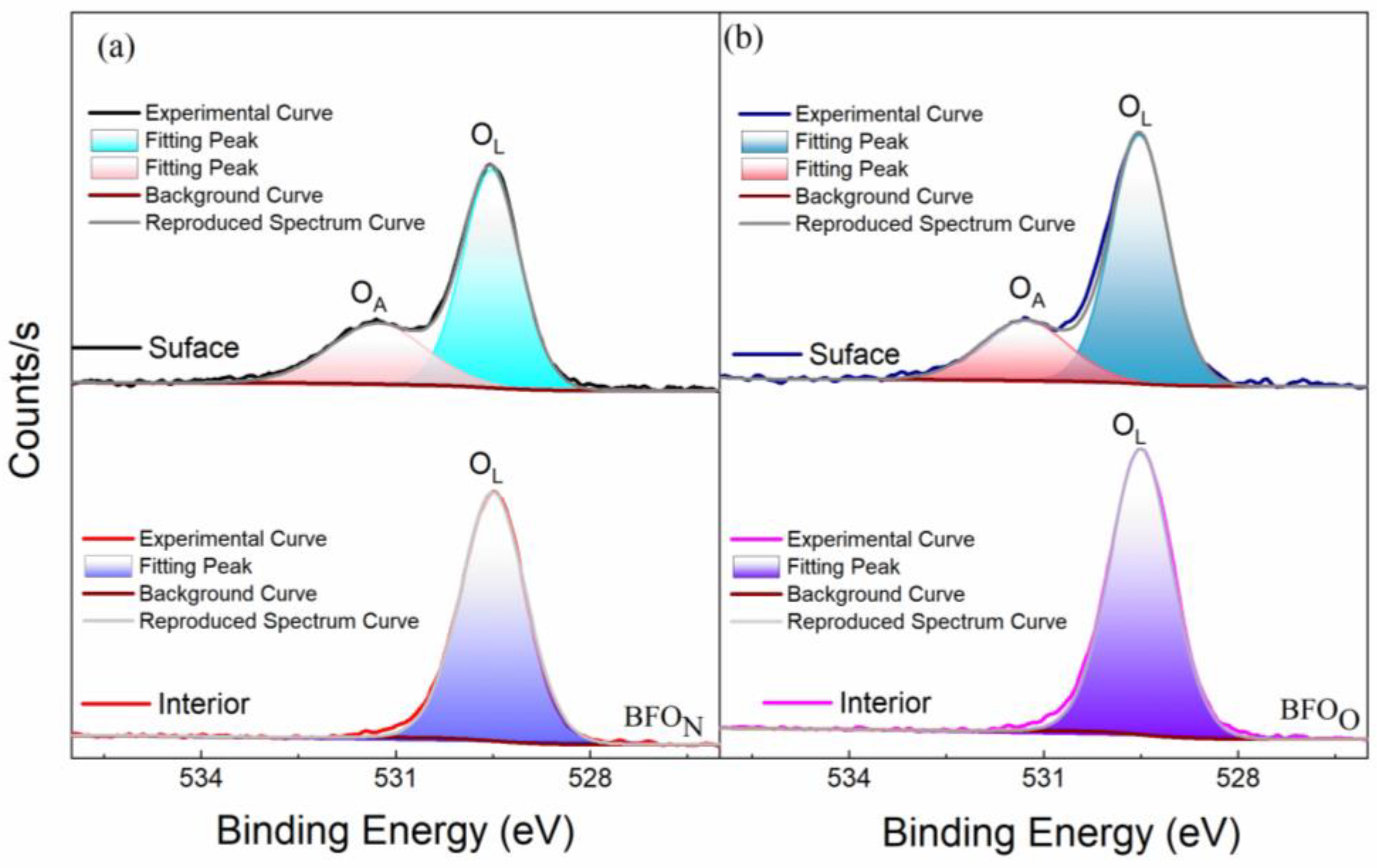
The X-ray photoelectron spectroscopy (XPS) spectrum of O1s core levels of the BFOO and BFON thin films are shown in Figure 3. A strong peak at ~529.5 eV was observed for the BFOO and BFON thin films, which corresponds to oxygen in the perovskite lattice (OL). The peak at ~531.2 eV is the surface-absorbed oxygen (OA) [23]. To verify this, the surface of the BFOO and BFON films were etched to a thickness of ~3 nm. No peaks could be obtained at ~531.2 eV at the interior of the BFOO and BFON thin films. Furthermore, no obvious oxygen vacancy peak was observed in the BFO films, which may be related to the low number of oxygen vacancies in BFO films annealing in a rapid thermal annealing furnace in air.

3.1.2. Room-Temperature Electrical Properties

Figure 4 shows the electrical properties of BFOO and BFON films at 440 ± 5 °C. Figure 4a,b present the typical P-E loops of the BiFeO3 films. When the applied electric field was sufficiently large, well-formed rectangular-shaped, saturated P-E hysteresis loops were observed in the BFON and BFOO films. A large remanent polarization (Pr~78.1 μC/cm2) and high rectangularity (~91.3%) of the hysteresis loop were observed in the BFON film at the applied electric field of 1165.2 kV/cm. A high remanent polarization (Pr~79.6 μC/cm2) and good rectangularity (~86.8%) of the hysteresis loop were observed in the BFOO film at the applied electric field of 915.4 kV/cm. Compared with the BFON film, the P-E loops of the BFOO film displayed a somewhat roundish shape, indicating contributions from the leakage current induced by the voids, and more grain boundaries [25]. The normalized pulsed polarization (ΔP = P* (switched polarization) − Pˆ (nonswitched polarization), their retention time, and switching cycles are shown in Figure 4c,d. Both the BFON and BFOO films exhibited good charge-retaining ability for up to 1.0 × 10³ s. The improved charge-retaining ability (~1% loss) of the BFON film compared with that (~4% loss) for the BFOO film was attributed to the reduced domain backswitching induced by the grain boundary defects and voids in the former compared with the latter [25]. As shown in Figure 4d, good fatigue resistance of up to 1.0 × 10⁹ switching cycles was observed in both the BFON and BFOO films, which could be attributed to the improved interface from using Al substrates as well as the low oxygen vacancies, as discussed in Figure 3.
Leakage performances for the BFOO and BFON films are shown in Figure 5; the soaking time was 500 ms during the leakage test under the unswitched linear mode [26]. From Figure 5a,b, we can see that the leakage current density (J) of the BFON film was slightly higher than 1-fold that of BFOO film but less than 2-fold, which can be ascribed to the slightly lower oxygen vacancy concentration in the BFOO film, as discussed in Figure 3. To clarify the dominant leakage mechanism involved in BFO films, linear fittings of the leakage behavior are shown in Figure 5c–f based on leakage mechanism formulas [27]. From Figure 5c,e, the Fowler–Nordheim tunneling (FN tunneling) [ln (J/E2)∝1/E] mechanism is induced by the interface electrons activated into the conduction band by the tunneling involved in the BFON film under the positive electric field (<251.0 kV/cm) [28,29]. The FN tunneling mechanism observed at the low electric field may be related to the good crystallization of the BFON film. The Ohmic conduction mechanism (log J∝log E) can be observed at a high electric field (>251.0 kV/cm), which should be related to the free oxygen vacancies in the film under the positive electric field. With an increasing electric field, the electrons transitioning from the interface to the body may form defect complexes with oxygen vacancies. The formation of defect complexes suppresses the electron transition from the interface to the conduction band and changes the leakage mechanism [30]. In a negative electric field, the FN tunneling mechanism (<326.3 kV/cm) and space-charge-limited conduction (SCLC) (log J∝2log E) were involved in the leakage behavior of the BFON film. From Figure 5d,f, the SCLC mechanism (<100.4 kV/cm) and the FN tunneling mechanism (>100.4 kV/cm) were predominant under a positive electric field. The Ohmic conduction mechanism (<150.6 kV/cm) and FN tunneling mechanism (>150.6 kV/cm) can be observed under the negative electric field.
According to the above discussion, it can be concluded that by adopting a N2-rich atmosphere, improved crystalline quality could be achieved in the BFO films at 440 ± 5 °C, resulting in better ferroelectric properties. Furthermore, a lower annealing temperature was expected for the BiFeO3 films with Al substrates and a N2-rich atmosphere. Therefore, an attempt was made to fabricate the BFO films below the annealing temperature of 400 °C. Finally, BFO films with adequate electric properties were achieved a low temperature of 365 ± 5 °C (BFON365) on Al substrates under a N2-rich atmosphere. The detailed properties of the BFON365 film are shown in Figure 6 and Figure 7.

3.2. Performance of BiFeO3 Films Annealed at 365 ± 5 °C under a N2-Rich Atmospheres

3.2.1. Microstructure Analysis

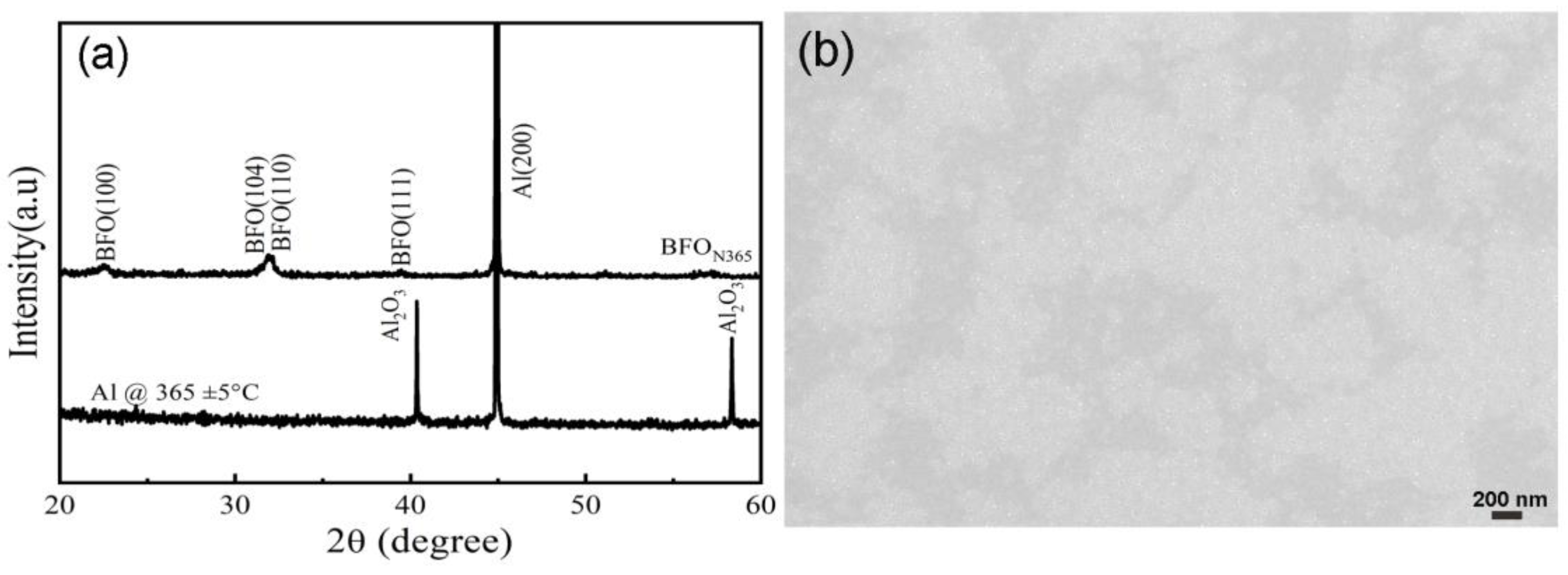
The XRD 2θ-scan pattern and surface SEM image of the BFON365 film are shown in Figure 6. A bulk-like random polycrystalline structure with obvious (100) and (110)/(104) peaks was observed, indicating that the BFO films were crystallized even at a low annealing temperature of 365 ± 5 °C. A dense morphology with fine nanograins was clearly revealed, indicating that the film had crystallized at this low annealing temperature.

3.2.2. Room-Temperature Electrical Properties

Typical P-E loops were observed in Figure 7a for the BFON365 film, and a sizable remnant polarization (Pr~70 μC/cm2) and good rectangularity (~75.0%) of the hysteresis loop at the applied electric field of 1118.1 kV/cm were obtained. These observations indicate that Al foil serves as a suitable substrate for fabricating ferroelectric BiFeO3 films under low annealing temperatures. As shown in Figure 7b, the leakage current density of BFON365 was lower than ~1 × 10⁻⁴ A/cm2 under the electric field of 353.5 kV/cm. Figure 7c,d illustrates that good fatigue resistance with a low loss (~5.8%) of up to 1.0 × 10⁹ switching cycles for positive polarization was observed, and the loss for negative polarization under the same testing conditions was ~27%. Retention testing was carried out for BFON365 films; a degradation of ~29% for the negative polarization was observed after 1.0 × 10³ s, which is much higher than that for the positive polarization (~14%). The improved fatigue and retention performance at the positive side could be ascribed to the reduced interfacial defects (e.g., vacancies, grain boundaries or amorphous regions) at the bottom electrode after a long exposure to a processing temperature. The achieved ferroelectric characteristics of a BFO film directly deposited onto the substrate without a buffer layer under the temperature of 400 °C have not previously been reported. This was attributed to the N2-rich atmosphere, the Al foil substrate, as well as the homogeneous precursor solution.

4. Conclusions

In summary, BFO films were successfully fabricated at a low annealing temperature (<450 °C). A common base metal, aluminum foil, was adopted as the bottom electrode and substrate for the BFO ferroelectric film. Compared with an oxygen-rich atmosphere, a nitrogen-rich atmosphere was more conducive to optimizing the performance of BFO films. Along with excellent retention and fatigue properties, P-E loops with a large Pr value (~78.1 μC/cm2) and high rectangularity (~91.3%) at the applied electric field of 1165.2 kV/cm were obtained in the BFO films deposited under a N2-rich atmosphere at 440 ± 5 °C. By using a N2-rich atmosphere as well as Al substrates, BFO films with good electrical properties were achieved a very low temperature of 365 ± 5 °C. This offers a new strategy for lowering the annealing temperature of BFO films.

Funding

This research was funded by the Natural Science Foundation of Shandong Province (grant number ZR2022ME075).

Data Availability Statement

Data are available upon request to the corresponding author.

Conflicts of Interest

The author declares no conflicts of interest. The funders had no role in the design of the study; in the collection, analyses, or interpretation of data; in the writing of the manuscript; or in the decision to publish the results.

References

  1. Wu, J.; Wang, J. Orientation dependence of ferroelectric behavior of BiFeO3 thin films. J. Appl. Phys. 2009, 106, 104111. [Google Scholar] [CrossRef]
  2. Yan, J.; Ouyang, J.; Cheng, H.B.; Yan, P. Low temperature deposition of BiFeO3 films on Ti foils for piezoelectric applications. Scr. Mater. 2021, 204, 114152. [Google Scholar] [CrossRef]
  3. Wang, J.; Neaton, J.B.; Zheng, H.; Nagarajan, V.; Ogale, S.B.; Liu, B.; Viehland, D.; Vaithyanathan, V.; Schlom, D.G.; Waghmare, U.V.; et al. Epitaxial BiFeO3 multiferroic thin film heterostructures. Science 2003, 299, 1719–1722. [Google Scholar] [CrossRef] [PubMed]
  4. Wu, J.G.; Fan, Z.; Xiao, D.Q.; Zhu, J.G.; Wang, J. Multiferroic bismuth ferrite-based materials for multifunctional applications: Ceramic bulks, thin films and nanostructures. Prog. Mater. Sci. 2016, 84, 335–402. [Google Scholar] [CrossRef]
  5. Yang, B.B.; Jin, L.H.; Wei, R.H.; Tang, X.W.; Hu, L.; Tong, P.; Yang, J.; Song, W.H.; Dai, J.M.; Zhu, X.B.; et al. Chemical solution route for high-quality multiferroic BiFeO3 thin films. Small 2021, 17, 1903663. [Google Scholar] [CrossRef] [PubMed]
  6. Catalan, G.; Scott, J.F. Physics and applications of bismuth ferrite. Adv. Mater. 2010, 21, 2463–2485. [Google Scholar] [CrossRef]
  7. Zhu, H.F.; Yang, Y.L.; Ren, W.; Niu, M.M.; Hu, W.; Ma, H.F.; Ouyang, J. Rhombohedral BiFeO3 thick films integrated on Si with a giant electric polarization and prominent piezoelectricity. Acta Mater. 2020, 200, 305–314. [Google Scholar] [CrossRef]
  8. Tomczyk, M.; Bretos, I.; Jiménez, R.; Mahajan, A.; Ramana, E.V.; Calzada, M.L.; Vilarinho, P.M. Direct fabrication of BiFeO3 thin films on polyimide substrates for flexible electronics. J. Mater. Chem. C 2017, 5, 12529–12537. [Google Scholar] [CrossRef]
  9. Wen, Z.; Shen, X.; Wu, J.X.; Wu, D.; Li, A.D.; Yang, B.; Wang, Z.; Chen, H.Z.; Wang, J.L. Temperature-dependent leakage current characteristics of Pr and Mn cosubstituted BiFeO3 thin films. Appl. Phys. Lett. 2010, 96, 202904. [Google Scholar] [CrossRef]
  10. Yan, J.; Hu, G.D.; Chen, X.M.; Wu, W.B.; Yang, C.H. Ferroelectric properties, morphologies, and leakage currents of Bi0.97La0.03FeO3 thin films deposited on indium tin oxide/glass substrates. J. Appl. Phys. 2008, 104, 076103. [Google Scholar] [CrossRef]
  11. Chen, D.Y.; Chen, Z.H.; He, Q.; Clarkson, J.D.; Serrao, C.R.; Yadav, A.K.; Nowakowski, M.E.; Fan, Z.; You, L.; Gao, X.S.; et al. Interface engineering of domain structures in BiFeO3 thin films. Nano Lett. 2017, 17, 486–493. [Google Scholar] [CrossRef] [PubMed]
  12. Jang, H.W.; Ortiz, D.; Baek, S.H.; Folkman, C.M.; Das, R.R.; Shafer, P.; Chen, Y.B.; Nelson, C.T.; Pan, X.Q.; Ramesh, R.; et al. Domain engineering for enhanced ferroelectric properties of epitaxial (001) BiFeO thin films. Adv. Mater. 2009, 21, 817–823. [Google Scholar] [CrossRef]
  13. Yan, J.; Zhu, H.F.; Ouyang, J.; Kanno, I.; Yan, P.; Wang, Y.Y.; Onishi, K.; Nishikado, T. Highly (00l)-textured BiFeO3 thick films integrated on stainless steel foils with an optimized piezoelectric performance. J. Eur. Ceram. Soc. 2022, 42, 3454–3462. [Google Scholar] [CrossRef]
  14. Chen, X.M.; Hu, G.D.; Wang, J.C.; Cheng, L.; Yang, C.H.; Wu, W.B. Thickness effects of Bi0.89Ti0.11FeO3 thin films deposited on PbZr0.2Ti0.79Nb0.01O3 buffer layers. J. Alloys Compd. 2011, 509, 431–434. [Google Scholar] [CrossRef]
  15. Li, H.; Ding, Y.W.; Ren, K.J.; Zeng, Z.X.; Chen, C.; Deng, X.L.; Gao, R.L.; Cai, W.; Wang, Z.H.; Fu, C.L.; et al. Effect of rapid/slow annealing routes on the magnetic and photoelectric properties of BiFeO3/CoFe2O4 multilayer thin films. J. Alloys Compd. 2024, 989, 174203. [Google Scholar] [CrossRef]
  16. Pan, T.M.; Chen, Z.Y.; Weng, W.C.; Her, J.L. Electrical and structural properties of BiFeO3 thin films with four distinct buffer layers: La2O3, Pr2O3, Sm2O3, and Tm2O3. Phys. B Condens. Matter. 2024, 689, 416219. [Google Scholar] [CrossRef]
  17. Zhang, J.; Dai, J.Q.; Zhang, G.C.; Zhu, X.J. Significantly improved ferroelectric properties of (Zn,Co) co-doped BiFeO3 thin films. prepared by sol-gel method. Ceram. Int. 2024, 50, 28449–28457. [Google Scholar] [CrossRef]
  18. Wang, Y.P.; Zhou, L.; Zhang, M.F.; Chen, X.Y.; Liu, J.M.; Liu, Z.G. Room-Temperature Saturated Ferroelectric Polarization in BiFeO3 Ceramics Synthesized by Rapid Liquid Phase Sintering. Appl. Phys. Lett. 2004, 84, 1731–1733. [Google Scholar] [CrossRef]
  19. Palkar, V.R.; Pinto, R. BiFeO3 thin films: Novel effects. Pramana J. Phys. 2002, 58, 1003–1008. [Google Scholar] [CrossRef]
  20. Kingon, A.I.; Srinivasan, S. Lead zirconate titanate thin films directly on copper electrodes for ferroelectric, dielectric and piezoelectric applications. Nat. Mater. 2005, 4, 233–237. [Google Scholar] [CrossRef]
  21. Hidnert, P.; Krider, H.S. Thermal Expansion of Aluminum and Some Aluminum Alloys. J. Res. Natl. Bur. Stand. 1952, 48, 209–220. [Google Scholar] [CrossRef]
  22. Yim, W.M.; Paff, R.J. Thermal expansion of AlN, sapphire, and silicon. J. Appl. Phys. 1974, 45, 1456–1457. [Google Scholar] [CrossRef]
  23. Niu, M.M.; Zhu, H.F.; Wang, Y.Y.; Yan, J.; Chen, N.; Yan, P.; Ouyang, J. Integration-friendly, chemically stoichiometric BiFeO3 films with a piezoelectric performance challenging that of PZT. ACS Appl. Mater. Interfaces 2020, 12, 33899–33907. [Google Scholar] [CrossRef] [PubMed]
  24. Liu, H.Y.; Pu, Y.P.; Shi, X.; Yuan, Q.B. Dielectric and ferroelectric properties of BiFeO3 ceramics sintered in different atmospheres. Ceram. Int. 2013, 39, S217–S220. [Google Scholar] [CrossRef]
  25. Lee, J.S.; Joo, S.K. Analysis of grain-boundary effects on the electrical properties of Pb(Zr,Ti)O3 thin films. Appl. Phys. Lett. 2002, 81, 2602–2604. [Google Scholar] [CrossRef]
  26. Yan, J.; Jiang, X.M.; Hu, G.D. Leakage mechanisms of partially self-polarized BiFeO3 film. Ceram. Int. 2018, 44, 13765–13772. [Google Scholar] [CrossRef]
  27. Sun, W.; Zhou, Z.; Luo, J.; Wang, K.; Li, J.F. Leakage current characteristics and Sm/Ti doping effect in BiFeO3 thin films on silicon wafers. J. Appl. Phys. 2017, 121, 64101–64107. [Google Scholar] [CrossRef]
  28. Luo, J.M.; Lin, S.P.; Zheng, Y.; Wang, B. Nonpolar resistive switching in Mn-doped BiFeO3 thin films by chemical solution deposition. Appl. Phys. Lett. 2012, 101, 62902–62903. [Google Scholar] [CrossRef]
  29. Yang, H.; Wang, Y.Q.; Wang, H.; Jia, Q.X. Oxygen concentration and its effect on the leakage current in BiFeO3 thin films. Appl. Phys. Lett. 2010, 96, 12909–12913. [Google Scholar] [CrossRef]
  30. Hu, G.D.; Fan, S.H.; Yang, C.H.; Wu, W.B. Low leakage current and enhanced ferroelectric properties of Ti and Zn codoped BiFeO3 thin film. Appl. Phys. Lett. 2008, 92, 192905–192913. [Google Scholar] [CrossRef]
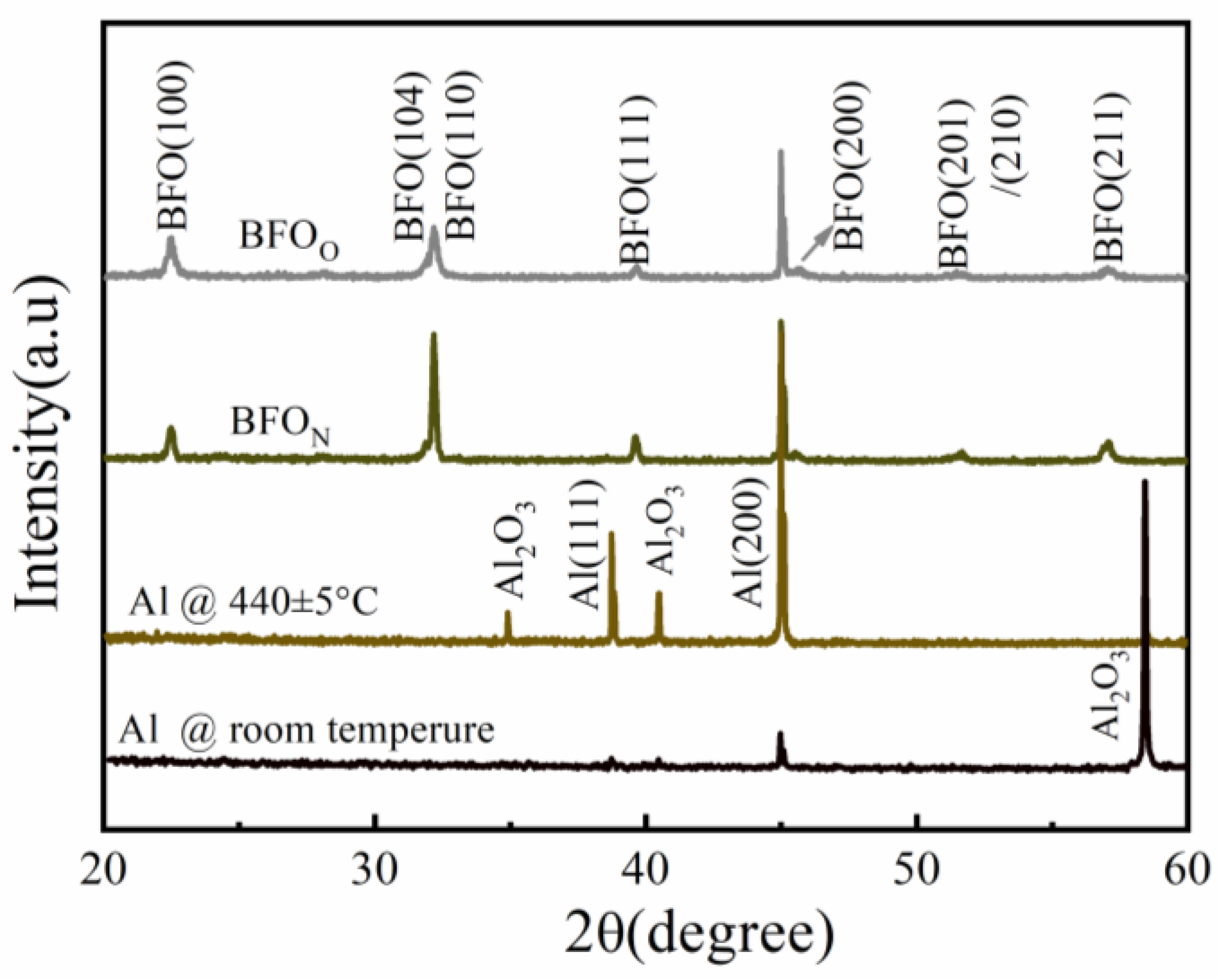
Figure 1. (Color online) X-ray diffraction (XRD) 2θ-scan patterns of the Al foil and BFO films deposited in N2-rich and O2-rich atmospheres at 440 ± 5 °C.
Nanomaterials 14 01343 g001
Figure 2. Surface SEM images for (a) the BFOO and (b) BFON films at 440 ± 5 °C.
Nanomaterials 14 01343 g002
Figure 3. (a,b) are the XPS spectra of the O1s core level for the surface as well as the interior of the BFOO and BFON thin films, respectively.
Nanomaterials 14 01343 g003
Figure 4. (Color online) room-temperature polarization–electric field (P-E) curves for (a) the BFOO and (b) BFON films at 440 ± 5 °C. (c) Retention and (d) fatigue properties investigated for the BFOO and BFON films at 440 ± 5 °C.
Nanomaterials 14 01343 g004
Figure 5. (Color online) (a,b) are the leakage current density–electric field (J–E) curves for BFOO and BFON films annealed at 440 ± 5 °C, respectively. (cf) are the curve-fitting results for the J–E curves in (a,b).
Nanomaterials 14 01343 g005
Figure 6. XRD 2θ-scan patterns (a) of the BFON365 film and Al foil annealed at 365 ± 5 °C and the surface SEM image (b) of the BFON365 film.
Nanomaterials 14 01343 g006
Figure 7. (Color online) room-temperature (a) P–E curves and (b) leakage property, and the normalized pulsed polarization as a function of (c) switching cycles and (d) the retention time for the BFON365 film.
Nanomaterials 14 01343 g007
Table 1. The average grain size for the BFON and BFOO films.
FilmBFONBFOO
Global average grain size via the Scherrer formula(100)-oriented grains180 nm120 nm
(111)-oriented grains75 nm50 nm
(211)-oriented grains30 nm23 nm
Local average grain size via SEM analysis (using 100 grains)105 nm55 nm
Disclaimer/Publisher’s Note: The statements, opinions and data contained in all publications are solely those of the individual author(s) and contributor(s) and not of MDPI and/or the editor(s). MDPI and/or the editor(s) disclaim responsibility for any injury to people or property resulting from any ideas, methods, instructions or products referred to in the content.