Abstract
Carbon nanotube (CNT)-based nanocomposites have found applications in making sensors for various types of physiological sensing. However, the sensors’ fabrication process is usually complex, multistep, and requires longtime mixing and hazardous solvents that can be harmful to the environment. Here, we report a flexible dry silver (Ag)/CNT/polydimethylsiloxane (PDMS) nanocomposite-based sensor made by a solvent-free, low-temperature, time-effective, and simple approach for electrophysiological recording. By mechanical compression and thermal treatment of Ag/CNT, a connected conductive network of the fillers was formed, after which the PDMS was added as a polymer matrix. The CNTs make a continuous network for electrons transport, endowing the nanocomposite with high electrical conductivity, mechanical strength, and durability. This process is solvent-free and does not require a high temperature or complex mixing procedure. The sensor shows high flexibility and good conductivity. High-quality electroencephalography (EEG) and electrooculography (EOG) were performed using fabricated dry sensors. Our results show that the Ag/CNT/PDMS sensor has comparable skin–sensor interface impedance with commercial Ag/AgCl-coated dry electrodes, better performance for noninvasive electrophysiological signal recording, and a higher signal-to-noise ratio (SNR) even after 8 months of storage. The SNR of electrophysiological signal recording was measured to be 26.83 dB for our developed sensors versus 25.23 dB for commercial Ag/AgCl-coated dry electrodes. Our process of compress-heating the functional fillers provides a universal approach to fabricate various types of nanocomposites with different nanofillers and desired electrical and mechanical properties.
1. Introduction
The development of soft and flexible wearable sensors has attracted attention due to the mechanical compatibility of such sensors with soft and stretchable tissue, electrical conductivity, and biocompatibility. Such wearable sensors, when integrated with electronic circuits, provide a promising platform for human–machine interface, rehabilitation, medical diagnosis, and continuous health monitoring [,,,,,,,]. To create a conformable and robust interface between the sensor and soft, dynamic human skin, various approaches have been implemented, including exploiting deformable structures and employing intrinsically flexible materials [,,,,,,]. During recent decades, various types of soft and conductive polymers and composites have been developed. These composites and polymers are made of polymers and/or elastomers with conductive fillers, such as carbon-based nanomaterials and metal nanoparticles [,,,,,,]. Among the developed composites, carbon nanotube (CNT)-based nanocomposites have been widely used for the fabrication of wearable electronics due to the inherent stretchability, high electrical conductivity, and processibility of CNTs as conductive fillers in many polymer networks [,,,,]. The conventional strategies used to fabricate CNT/polymer nanocomposites are solution mixing and dry/melt blending [,,,]. The solution mixing method is technically simple and scalable, but it requires the consumption of a large amount of solvent, which is harmful to the environment [,]. Melt blending is toxin-free and cost-effective, but it is only compatible with thermoplastic polymers. Also, poor dispersion of the filler in the polymer matrix specifically with a higher filler content is a likely scenario that affects the electrical conductivity and mechanical characteristics of nanocomposites and increases the polymer’s stiffness []. Thermoplastic-based nanocomposites are also made by dry mixing CNT and polymer powders followed by hot pressing, but the high degree of hardness of polymers limits their application in flexible devices []. Unconventional methods of making CNT/polymer nanocomposites include the spray coating and drop drying of CNT dispersion on the surface of polymer fibers or foams, though they may not be safe to use as biosensors mainly because of the poor adhesion of CNT to the polymer or foam surfaces [,,,]. The use of CVD-grown CNTs to make conductive nanocomposites with anisotropic strength has been reported as well, but only thin layers of conductive nanocomposites can be made by coating the grown CNTs with a polymer precursor, and the fabrication process is complex [,]. To address the abovementioned issues, we have developed a low-cost, time-effective, scalable, solvent-free method to fabricate CNT nanomaterials with high electrical conductivity.
To form a connected network of CNTs in the polydimethylsiloxane (PDMS) matrix and ensure good electrical conductivity, CNTs were compressed and thermally treated before soaking them in PDMS and curing the PDMS. The CNTs form a stable network under compression, which results in the high conductivity of nanocomposites and their enhanced mechanical strength and durability. This process (1) addresses the use of a large amount of chemicals and solvents and high temperatures in the conventional methods of making nanocomposites, (2) suggests a universal approach to fabricating various types of nanocomposites with different fillers and desired electrical and mechanical properties, and (3) enables one-step simple and combined surface modification with silver unlike conventional methods of surface modification that are multistep, complex, and require further chemical processing and energy consumption. Sensors produced using our developed method are reusable, have a large life span, and show robust operation; further, they do not cause skin irritations and allergic reactions.
2. Results and Discussions
The solvent-free and cost-efficient process of making CNT/PDMS nanocomposites is shown in Figure 1a. PDMS was selected as the polymer matrix due to its nontoxicity, flexibility, thermal stability, simple processing, and biocompatibility [,]. To fabricate CNT/PDMS nanocomposite-based sensors containing a thin layer of silver nanoparticles at the interface with the skin, first the electrical and mechanical characteristics of CNT/PDMS nanocomposites were studied, and our solvent-free fabrication process was optimized.
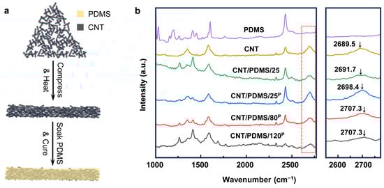
Figure 1.
(a) Illustration of the fabrication process of compressed CNT/PDMS nanocomposites. (b) Raman spectrum of PDMS, CNT, CNT/PDMS/25, CNT/PDMS/25P, CNT/PDMS/80P, and CNT/PDMS/120P.
To fabricate CNT/PDMS nanocomposites-based sensors, a continuous and connected network of CNTs over a large area was formed by co-applying compression and heat to the CNTs to create an electrically conductive network. Then, the CNT network was soaked in the PDMS precursor, and the PDMS was cured to form flexible electrodes, as shown in Figure 1a and Figure S1. At first, the effects of the compression and heat applied to CNTs on the electrical and mechanical characteristics of nanocomposite samples were studied to find the optimum fabrication parameters for making the sensor. A series of CNT/PDMS nanocomposites were prepared with/without applying compression at different temperatures. CNT/PDMS/25 was fabricated at 25 °C without compressing the CNTs; CNT/PDMS/25P, CNT/PDMS/80P, and CNT/PDMS/120P were made by compressing the CNTs under 7.4 × 10³ N/m2 of pressure at 25, 80, and 120 °C, respectively. Figure 1b shows the results of Raman spectroscopy performed on the CNT/PDMS nanocomposites made at different compressions and temperatures. Our results suggest that the applied external compression/heat to CNTs and the presence of the polymer matrix induce residual strain on the CNTs, resulting in shifting the characteristic Raman peak of CNTs from 2689.5 cm−1 to higher wavenumbers [,,]. As demonstrated in Figure 1b, when no compression and heat is applied to CNTs, the Raman peak of CNT/PDMS/25 appears at 2691.7 cm−1, while the Raman peak of CNT/PDMS/25P fabricated with compression is located at 2698.4 cm−1, and it further shifted to 2707.3 cm−1 when the CNTs were compressed under the same pressure at higher temperatures of 80 °C (CNT/PDMS/80P) and 120 °C (CNT/PDMS/120P). These results show that both heat and compression cause a rise in the residual strain in CNTs and contribute to forming a more compact CNT network, therefore enhancing the electrical and mechanical characteristics of the CNT/PDMS nanocomposites.
The sheet resistances of CNT/PDMS/25, CNT/PDMS/25P, CNT/PDMS/80P, and CNT/PDMS/120P were measured to be 663 ± 32, 340 ± 24, 247 ± 19, and 216 ± 25 Ω/sq, respectively (Figure 2a). The results indicate that the conductivity of the nanocomposite increases by increasing the temperature from 25 °C to 120 °C and by applying compression to the CNTs, as shown in Figure 2b. The conductivity was 0.75 ± 0.01, 2.93 ± 0.02, 3.67 ± 0.02, and 3.70 ± 0.05 S/m for CNT/PDMS/25, CNT/PDMS/25P, CNT/PDMS/80P, and CNT/PDMS/120P, respectively. Figure 2b indicates a 389% improvement in the conductivity of CNT/PDMS/80P in comparison with CNT/PDMS/25. However, our results show that further increasing the temperature from 80 to 120 °C did not improve the conductivity of the nanocomposites significantly, and therefore CNT/PDMS/80P nanocomposite is the best candidate for the fabrication of the sensors. Figure 2c shows the effect of mechanical tensile strain on the electrical resistance of nanocomposites produced at different conditions. The results show that the CNT/PDMS/25 nanocomposite is the most susceptible sample to the strain, showing a 200% increase in the electrical resistance due to applying 50% of tensile strain, while the nanocomposite produced using compressed CNTs at 80 °C shows only a 10% increase in the electrical resistance when 50% of tensile strain was applied. This is mainly due to the better-formed network of CNTs in the CNT/PDMS/80P nanocomposite.
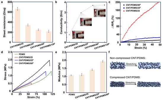
Figure 2.
The effect of applying compression and heat during the fabrication of CNT/PDMS nanocomposite on its electrical and mechanical properties. (a) The sheet resistance and (b) the conductivity of CNT/PDMS/25, CNT/PDMS/25P, CNT/PDMS/80P, and CNT/PDMS/120P samples; inset photos of b show the brightness of an LED light connected in series to nanocomposite samples. (c) The changes in the resistance of CNT/PDMS/25, CNT/PDMS/25P, and CNT/PDMS/80P samples versus tensile strain. (d) The stress–strain curves of PDMS, CNT/PDMS/25, CNT/PDMS/25P, and CNT/PDMS/80P nanocomposites. (e) The Young’s modulus of PDMS, CNT/PDMS/25, CNT/PDMS/25P, and CNT/PDMS/80P nanocomposites. (f) Illustration of the changes induced in the network of CNTs in nanocomposites due to applying tensile strain to them.
Figure 2d shows the stress–strain plot of PDMS, CNT/PDMS/25, CNT/PDMS/25P, and CNT/PDMS/80P. As the results indicate, the nanocomposite made under no compression at 25 °C shows poor mechanical performance with a much lower elongation at break of 55%, in comparison with the pure PDMS matrix with an elongation at break of approximately 120%. This can be attributed to the formation of voids and pores in the CNT/PDMS/25 sample (Supplementary Figure S2). The results show that the elongation at break increases by applying compression and heat to CNTs. The CNT/PDMS nanocomposites fabricated by compressing CNTs at 25 and 80 °C show improved elongation at break of 100% and 110%, respectively, of which the latter is close to the PDMS matrix. The extracted values of the Young’s modulus of the samples, shown in Figure 2e, suggest moduli of 1.06, 1.10, 1.41, and 1.92 MPa for PDMS, CNT/PDMS/25, CNT/PDMS/25P, and CNT/PDMS/80P, respectively. These results show that the incorporation of CNTs has greatly improved the mechanical strength of the compressed CNT/PDMS nanocomposites, which is mainly attributed to the formation of CNT networks, as demonstrated in Figure 2f.
The collective electrical and mechanical characteristics of our studied CNT/PDMS nanocomposites produced under different applied compressions and temperatures suggest that the compressed CNT/PDMS nanocomposite prepared under 7.4 × 10³ N/m2 pressure at 80 °C (CNT/PDMS/80P) shows higher electrical conductivity as well as larger elongation at break and a higher elastic modulus, indicating the mechanical strength and durability of the developed nanocomposites.
Figure 3a and Figure S3 show the change in the electrical resistance of the CNT/PDMS/80P nanocomposites versus the bending radius. Our results indicate the high stability of the nanocomposite polymer, with only a 4.5% increase in the electrical resistance at a 1.5 mm bending radius. The changes in the electrical resistance of the CNT/PDMS/80P nanocomposites within the temperature range of 25 °C to 40 °C, presented in Figure 3b, show only a 6% decrease in the electrical resistance of the nanocomposite, indicating that the change in the skin’s temperature would not have an adverse effect on the electrophysiological signal measurements. The hysteresis plot in Figure 3c shows five stress–strain cycles of CNT/PDMS/80P nanocomposites. The CNT/PDMS/80P nanocomposite shows a closed hysteresis loop after the first stress–strain cycle when the tensile strain applied to the nanocomposite changes from 0% to 50% and from 50% to 0%, suggesting the good elasticity of the nanocomposite. To investigate the fatigue resistance of CNT/PDMS/80P nanocomposites, 10,000 and 5000 successive cycles of tensile loading–unloading were carried out for up to 30% and 50% of applied tensile strain, respectively (Figure 3d,e and Figure S4). The measured stress reduced by only 0.08 and 0.26 MPa after 10,000 strain cycles of 30% and 5000 successive cycles of 50% tensile strain. The corresponding energy dissipation in the sample under 50% of applied tensile strain shows to be stable around 7.5 MJ/m3 within the first five cycles, indicating the good anti-fatigue resistance and elasticity of the CNT/PDMS/80P nanocomposites.
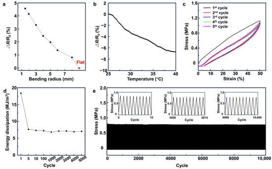
Figure 3.
The electrical and mechanical stability and durability of the CNT/PDMS nanocomposites. The change in the electrical resistance of CNT/PDMS/80P versus (a) bending radius and (b) temperature. (c) The loading–unloading curves (hysteresis) of successive cycles of CNT/PDMS/80P sample at a strain of 50%. (d) The energy dissipation at 1, 5, 10, 100, 1000, 2000, 3000, 4000, and 5000 cycles at a strain of 50%. (e) A total of 10,000 strain cycles of 30% for CNT/PDMS/80P sample.
To fabricate the sensor, in the first step, an acrylonitrile butadiene styrene (ABS) mold was printed using a 3D printer (Figure 4). Then, the surface of the mold was uniformly coated with silver nanoparticles to improve the skin–sensor interface before adding CNTs into the mold and soaking the network in PDMS. Next, multi-walled carbon nanotubes with a length and diameter of 5~20 µm and 16 ± 3.6 nm, respectively, were used to fill the mold. To make secure connections to the circuits, a thin copper strip (with a thickness of 220 μm) was placed within the CNT powder, and then they were compressed under 7.4 × 10³ N/m2 pressure at 80 °C for 6 h. Compression results in forming a network of CNTs [,]. In the next step, liquid PDMS (base and curing agent with a weight ratio of 10:1) was poured into the mold containing CNTs and silver nanoparticles. The liquid PDMS precursor penetrates within the formed network of CNT in 30 min. Finally, the sample was heated at 65 °C for 6 h to cure the PDMS. The sensor was then de-molded and used for electrophysiological recording. Our strategy of compressing and heating the conductive fillers provides a universal approach to fabricate conductive materials in a solvent-free and energy-saving way, compared with solution mixing and dry/melt blending that require a large amount of solvent and high energy consumption (such as a long milling times [,] and high temperature []), respectively.
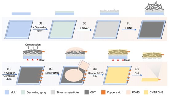
Figure 4.
Schematic of the fabrication process of silver nanoparticle/CNT/PDMS sensors. After applying the demolding spray on the surface of the mold, a thin layer of silver nanoparticles was added into the mold, followed by filling the mold with CNT, placing a copper strip, compressing, and applying heat. By soaking this combination in PDMS and curing the PDMS, the fabrication of the sensor was completed.
To study the suitability of the fabricated sensor for electrophysiological recording, two sensors were placed on the forearm next to the commercial Ag/AgCl wet gel electrodes and commercial Ag/AgCl dry electrodes as gold standards, and the electrode–skin interface impedance in the frequency range of 20 Hz to 5 kHz was measured using all these three types of sensors and electrodes. The results shown in Figure 5a indicate that the sensor–skin interface impedance of the Ag/CNT/PDMS/80P sensor is similar to that of the commercial Ag/AgCl dry electrodes and is slightly higher than Ag/AgCl wet gel electrodes (it is known that Ag/AgCl wet gel electrodes have the lowest electrode–skin interface impedance of all types of electrodes). These results indicate that our sensor makes an effective interface with the skin, which is critical for recording various types of electrophysiological signals. The application of our sensors for electrophysiological recordings was demonstrated by performing electroencephalography (EEG) and electrooculography (EOG) on the forehead. No conductive gel was applied at the interface between the sensors and the skin (Figure 5b). Figure 5c,d show the recoded alpha rhythm at 8–13 Hz by the Ag/CNT/PDMS/80P sensor and Ag/AgCl dry electrode at the Fp1 and Fp2 positions on the forehead when the eyes are open and when they are closed [,,]. The Ag/CNT/PDMS/80P sensor was placed in the Fpz position as the reference and ground electrodes [,]. The alpha rhythm was expected to appear when the eyes were closed and the subject was relaxing. EEG signals were measured while the subject kept their eyes open for 1 min and then closed them for another 1 min. The fast Fourier transform (FFT) results of the recorded data in Figure 5c,d show a clear alpha signal with a peak frequency of 12 Hz when the eyes were closed. It is worth noting that the amplitude of the alpha signal detected by the Ag/CNT/PDMS/80P sensor is higher than that measured by the commercial dry Ag/AgCl electrode. This is due to two main reasons: (1) higher electrical conductivity of Ag/CNT/PDMS/80P because of forming a compact network of CNTs in PDMS, and (2) improved interface with the skin due to the lower mechanical stiffness of our sensor.
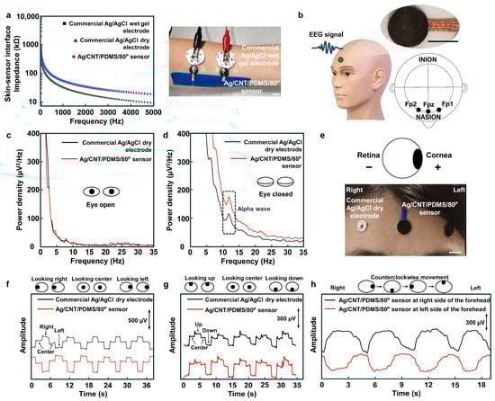
Figure 5.
The sensing performance of the Ag/CNT/PDMS/80P sensor. (a) The commercial Ag/AgCl dry electrode–, Ag/AgCl wet gel electrode– and Ag/CNT/PDMS/80P sensor–skin interface impedances measured on the forearm. The photo shows the measurement setup; scale bar is 1 cm. (b) The illustration of recording EEG signals; inset shows the photo of an Ag/CNT/PDMS/80P sensor. The scale bar is 1 cm. The comparison of EEG signals detected when the eyes were (c) open and (d) closed. (e) The configuration of the sensors for EOG measurements using commercial Ag/AgCl dry electrode and the Ag/CNT/PDMS/80P sensor. The scale bar is 1 cm. EOG signals recorded during eye movements of (f) looking left and right, (g) looking up and down, and (h) counterclockwise.
The application of the sensor for EOG recording was demonstrated as well. The EOG measures the electrostatic potential that exists between the retina and cornea during eyes movements [,]. Figure 5e shows the placement of our developed sensors and commercial dry Ag/AgCl electrodes as a standard electrode on the forehead for EOG recordings, where two Ag/CNT/PDMS/80P sensors are used as working and reference/ground electrodes, respectively, due to their high flexibility and conductivity [,,]. The EOG data recorded by the sensors were wirelessly transmitted to a laptop for signal processing. Figure 5f,g show the EOG signals recorded during ‘left’-, ‘right’-, ‘up’-, and ‘down’-ward movements of the eyes. Clear EOG signals were recorded using both the commercial Ag/AgCl dry electrodes and Ag/CNT/PDMS/80P sensors. The results show that the signal recorded using our sensor has a higher signal-to-noise ratio (SNR) of 26.83 dB compared with 25.23 dB for the commercial electrode. Figure 5h shows the EOG signals recorded using Ag/CNT/PDMS/80P sensors while the subject moved their eyes counterclockwise. To record real-time EOG during the rolling of the eyes, three Ag/CNT/PDMS/80P sensors were used, two attached above the eyebrows as working electrodes and one attached at the center of the forehead as a ground/reference electrode. The EOG signals in Figure 5h recorded by the sensor located on the right side of the forehead (black curve) and the sensor located on the left side of the forehead (red curve) during rolling of the eyes clearly show the recorded potential of the retina (negative) and cornea (positive) by each sensor while the eyes were moving. It is worth mentioning that during eye rolling, when both eyes are in their left corner, the cornea of the left eye that has positive potential is in the vicinity of the sensor on the left side of the forehead, and therefore we observe a positive potential recorded from the sensor on the left side of the forehead. However, at the same time, the retina of the right eyes with negative potential is in the vicinity of the sensor located on the right side of the forehead, and therefore we observe a negative potential recorded using the sensor located on the right side of the forehead. This results in a difference between the signals recorded using two sensors located on the left and right sides of the forehead. The EOG signals recorded during eye rolling could be further used for eye-movement-based communications, like eye writing.
Good mechanical and electrical characteristics of the compressed CNT/PDMS nanocomposite resulted in high stability and durability of the Ag/CNT/PDMS/80P sensors for long-term use. Figure 6a shows that high-quality EOG signals were recorded using Ag/CNT/PDMS/80P sensors that were stored for 8 months. The SNR of the recorded EOG signals using this Ag/CNT/PDMS/80P sensor was higher than that of the commercial Ag/AgCl dry electrodes. The high-quality recording and a higher SNR indicate that the electrical performance of Ag/CNT/PDMS/80P sensors was not affected over time. Moreover, to demonstrate the reliability of our sensor for repeated daily use, we replicated the routine maintenance and reuse of our sensor by repeated rinsing of the Ag/CNT/PDMS/80P sensor with water for 30s and letting dry in the ambient condition 20 times. As the inset photo of Figure 6a shows, there is no obvious change in the appearance of our sensors, and, further, the EOG measurements show no reduction in the SNR. Figure 6b shows that the Ag/CNT/PDMS/80P sensor did not cause any irritation after 8 h of wearing it. Furthermore, the small size and light weight of our sensor make it a comfortable and user-friendly sensor for various applications in wearable technology.
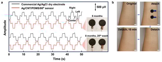
Figure 6.
The sensing performance of the Ag/CNT/PDMS/80P sensor on skin after 8 months of storage. (a) EOG signals recorded during the left–right eye movements measured by Ag/CNT/PDMS/80P sensor that was used, washed, and cleaned 20 times and stored for 8 months. The inset photos show the Ag/CNT/PDMS/80P sensors. (b) The skin before and after having the sensors on the forearm for 8 h. No redness or irritation were observed. The scale bar indicates 1 cm.
3. Conclusions
In this work, CNT/PDMS nanocomposites were made by a solvent-free, cost-efficient, and facile fabrication process and characterized. A sensor for the electrophysiological recording was fabricated from a batch of nanocomposites in which the CNT network in the polymer matrix was formed under 7.4 × 10³ N/m2 of pressure at 80 °C. The sensor showed high electrical conductivity, mechanical strength, as well as durability and long-term reliability. The harmless and effective fabrication approach avoids the use of any solvents, chemical waste, and high temperatures. The resulting sensor showed the capability for high-quality electroencephalography (EEG) and electrooculography (EOG) recordings. The SNR of the recorded EOG signals using our sensors has been higher than that of commercial Ag/AgCl dry electrodes. In addition, the SNR of our sensors remains higher than that of the Ag/AgCl dry electrodes after being stored for 8 months and repeating 20 cycles of washing and drying, showing its potential applications for long-term use in wearable technology. Our developed fabrication method is efficient in making flexible sensors characterized by high conductivity, good durability, and a robust interface with the skin, which provides a universal strategy to produce various conductive materials utilizing different fillers.
Supplementary Materials
The following supporting information can be downloaded at: https://www.mdpi.com/article/10.3390/bios14040188/s1, Figure S1: Detailed schematic diagram of the fabrication process of compressed CNT/PDMS nanocomposites; Figure S2: Optical microscope images of (a), (b) the CNT/PDMS/80P and (c), (d) CNT/PDMS/25; Figure S3: (a) Illustration of the process used to measure the change in electrical resistance of the sensor at different bending radii. (b) Photo showing the metal tubes with different radii used to bend the composites; Figure S4: Cyclic strain-stress test of the CNT/PDMS/80P for 5000 cycles at 50% strain.
Author Contributions
Conceptualization, S.K.A. and S.Z.; methodology, S.K.A. and S.Z.; software, A.Z.; validation, S.Z., A.Z., A.T. and C.W.; formal analysis, S.K.A. and S.Z.; investigation, S.Z.; resources, S.K.A.; data curation, S.Z.; writing—original draft preparation, S.Z.; writing—review and editing, S.K.A. and S.Z.; visualization, S.Z.; supervision, S.K.A.; project administration, S.K.A.; funding acquisition, S.K.A. All authors have read and agreed to the published version of the manuscript.
Funding
This research was funded by [NSERC Alliance Missions grant] grant number [ALLRP 570743-2021].
Institutional Review Board Statement
The study was conducted in accordance with the Declaration of Helsinki, and approved by the HEALTH SCIENCES & AFFILIATED TEACHING HOSPITALS RESEARCH ETHICS BOARD (HSREB) of QUEEN’S UNIVERSITY (6027092, 25/07/2023).
Informed Consent Statement
Informed consent was obtained from all subjects involved in the study.
Data Availability Statement
The original contributions presented in the study are included in the article/Supplementary Material, further inquiries can be directed to the corresponding author/s.
Acknowledgments
We acknowledge the support of NSERC and AAVAA Inc. through the NSERC Alliance Missions grant [funding reference number: ALLRP 570743-2021]. We acknowledge Alexander Nediak for editing the manuscript.
Conflicts of Interest
The authors declare no conflict of interest.
References
- Ban, S.; Lee, Y.J.; Kim, K.R.; Kim, J.-H.; Yeo, W.-H. Advances in Materials, Sensors, and Integrated Systems for Monitoring Eye Movements. Biosensors 2022, 12, 1039. [Google Scholar] [CrossRef] [PubMed]
- Hu, M.; Zhang, J.; Liu, Y.; Zheng, X.; Li, X.; Li, X.; Yang, H. Highly Conformal Polymers for Ambulatory Electrophysiological Sensing. Macromol. Rapid Commun. 2022, 43, 2200047. [Google Scholar] [CrossRef] [PubMed]
- Rao, Z.; Ershad, F.; Almasri, A.; Gonzalez, L.; Wu, X.; Yu, C. Soft electronics for the skin: From health monitors to human–machine interfaces. Adv. Mater. Technol. 2020, 5, 2000233. [Google Scholar] [CrossRef]
- Kabiri Ameri, S.; Ho, R.; Jang, H.; Tao, L.; Wang, Y.; Wang, L.; Schnyer, D.M.; Akinwande, D.; Lu, N. Graphene electronic tattoo sensors. ACS Nano 2017, 11, 7634–7641. [Google Scholar] [CrossRef] [PubMed]
- Wang, Y.; Qiu, Y.; Ameri, S.K.; Jang, H.; Dai, Z.; Huang, Y.; Lu, N. Low-cost, μm-thick, tape-free electronic tattoo sensors with minimized motion and sweat artifacts. NPJ Flex. Electron. 2018, 2, 6. [Google Scholar] [CrossRef]
- Ameri, S.K.; Kim, M.; Kuang, I.A.; Perera, W.K.; Alshiekh, M.; Jeong, H.; Topcu, U.; Akinwande, D.; Lu, N. Imperceptible electrooculography graphene sensor system for human–robot interface. NPJ 2d Mater. Appl. 2018, 2, 19. [Google Scholar] [CrossRef]
- Kireev, D.; Ameri, S.K.; Nederveld, A.; Kampfe, J.; Jang, H.; Lu, N.; Akinwande, D. Fabrication, characterization and applications of graphene electronic tattoos. Nat. Protoc. 2021, 16, 2395–2417. [Google Scholar] [CrossRef] [PubMed]
- Kim, D.-H.; Lu, N.; Ma, R.; Kim, Y.-S.; Kim, R.-H.; Wang, S.; Wu, J.; Won, S.M.; Tao, H.; Islam, A. Epidermal electronics. Science 2011, 333, 838–843. [Google Scholar] [CrossRef]
- Zhang, A.; Shyam, A.B.; Cunningham, A.M.; Williams, C.; Brissenden, A.; Bartley, A.; Amsden, B.; Docoslis, A.; Kontopoulou, M.; Ameri, S.K. Adhesive Wearable Sensors for Electroencephalography from Hairy Scalp. Adv. Healthc. Mater. 2023, 12, 2300142. [Google Scholar] [CrossRef]
- Zhang, A.; Ameri, S.K. Low-Modulus, Low-Motion-Artifact Sensor for Biological Signal Recording. In Proceedings of the 2022 IEEE Sensors, Dallas, TX, USA, 30 October–2 November 2022; pp. 1–4. [Google Scholar]
- Tian, L.; Zimmerman, B.; Akhtar, A.; Yu, K.J.; Moore, M.; Wu, J.; Larsen, R.J.; Lee, J.W.; Li, J.; Liu, Y.; et al. Large-area MRI-compatible epidermal electronic interfaces for prosthetic control and cognitive monitoring. Nat. Biomed. Eng. 2019, 3, 194–205. [Google Scholar] [CrossRef]
- La, T.G.; Qiu, S.; Scott, D.K.; Bakhtiari, R.; Kuziek, J.W.P.; Mathewson, K.E.; Rieger, J.; Chung, H.J. Two-layered and stretchable e-textile patches for wearable healthcare electronics. Adv. Healthc. Mater. 2018, 7, 1801033. [Google Scholar] [CrossRef]
- Jang, K.-I.; Li, K.; Chung, H.U.; Xu, S.; Jung, H.N.; Yang, Y.; Kwak, J.W.; Jung, H.H.; Song, J.; Yang, C.; et al. Self-assembled three dimensional network designs for soft electronics. Nat. Commun. 2017, 8, 15894. [Google Scholar] [CrossRef]
- Kim, N.; Lim, T.; Song, K.; Yang, S.; Lee, J. Stretchable multichannel electromyography sensor array covering large area for controlling home electronics with distinguishable signals from multiple muscles. ACS Appl. Mater. Interfaces 2016, 8, 21070–21076. [Google Scholar] [CrossRef] [PubMed]
- Norton, J.J.; Lee, D.S.; Lee, J.W.; Lee, W.; Kwon, O.; Won, P.; Jung, S.-Y.; Cheng, H.; Jeong, J.-W.; Akce, A. Soft, curved electrode systems capable of integration on the auricle as a persistent brain–computer interface. Proc. Natl. Acad. Sci. USA 2015, 112, 3920–3925. [Google Scholar] [CrossRef]
- Patel, S.; Ershad, F.; Lee, J.; Chacon-Alberty, L.; Wang, Y.; Morales-Garza, M.A.; Haces-Garcia, A.; Jang, S.; Gonzalez, L.; Contreras, L. Drawn-on-Skin Sensors from Fully Biocompatible Inks toward High-Quality Electrophysiology. Small 2022, 18, 2107099. [Google Scholar] [CrossRef]
- Qiao, Y.; Li, X.; Wang, J.; Ji, S.; Hirtz, T.; Tian, H.; Jian, J.; Cui, T.; Dong, Y.; Xu, X. Intelligent and Multifunctional Graphene Nanomesh Electronic Skin with High Comfort. Small 2022, 18, 2104810. [Google Scholar] [CrossRef]
- Zhang, L.; Liu, X.; Zhong, M.; Zhou, Y.; Wang, Y.; Yu, T.; Xu, X.; Shen, W.; Yang, L.; Liu, N. Micro-nano hybrid-structured conductive film with ultrawide range pressure-sensitivity and bioelectrical acquirability for ubiquitous wearable applications. Appl. Mater. Today 2020, 20, 100651. [Google Scholar] [CrossRef]
- Zhang, L.; Kumar, K.S.; He, H.; Cai, C.J.; He, X.; Gao, H.; Yue, S.; Li, C.; Seet, R.C.-S.; Ren, H. Fully organic compliant dry electrodes self-adhesive to skin for long-term motion-robust epidermal biopotential monitoring. Nat. Commun. 2020, 11, 4683. [Google Scholar] [CrossRef]
- Min, H.; Jang, S.; Kim, D.W.; Kim, J.; Baik, S.; Chun, S.; Pang, C. Highly air/water-permeable hierarchical mesh architectures for stretchable underwater electronic skin patches. ACS Appl. Mater. Interfaces 2020, 12, 14425–14432. [Google Scholar] [CrossRef]
- Lee, J.H.; Kim, H.; Hwang, J.-Y.; Chung, J.; Jang, T.-M.; Seo, D.G.; Gao, Y.; Lee, J.; Park, H.; Lee, S. 3D printed, customizable, and multifunctional smart electronic eyeglasses for wearable healthcare systems and human–machine Interfaces. ACS Appl. Mater. Interfaces 2020, 12, 21424–21432. [Google Scholar] [CrossRef]
- Stauffer, F.; Thielen, M.; Sauter, C.; Chardonnens, S.; Bachmann, S.; Tybrandt, K.; Peters, C.; Hierold, C.; Vörös, J. Skin conformal polymer electrodes for clinical ECG and EEG recordings. Adv. Healthc. Mater. 2018, 7, 1700994. [Google Scholar] [CrossRef] [PubMed]
- Wang, C.; Xia, K.; Wang, H.; Liang, X.; Yin, Z.; Zhang, Y. Advanced carbon for flexible and wearable electronics. Adv. Mater. 2019, 31, 1801072. [Google Scholar] [CrossRef] [PubMed]
- Lee, J.H.; Lee, S.M.; Byeon, H.J.; Hong, J.S.; Park, K.S.; Lee, S.-H. CNT/PDMS-based canal-typed ear electrodes for inconspicuous EEG recording. J. Neural Eng. 2014, 11, 046014. [Google Scholar]
- Lee, J.H.; Hwang, J.-Y.; Zhu, J.; Hwang, H.R.; Lee, S.M.; Cheng, H.; Lee, S.-H.; Hwang, S.-W. Flexible conductive composite integrated with personal earphone for wireless, real-time monitoring of electrophysiological signs. ACS Appl. Mater. Interfaces 2018, 10, 21184–21190. [Google Scholar] [CrossRef]
- Kim, T.; Park, J.; Sohn, J.; Cho, D.; Jeon, S. Bioinspired, Highly Stretchable, and Conductive Dry Adhesives Based on 1D-2D Hybrid Carbon Nanocomposites for All-in-One ECG Electrodes. ACS Nano 2016, 10, 4770–4778. [Google Scholar] [CrossRef]
- Lee, S.M.; Byeon, H.J.; Lee, J.H.; Baek, D.H.; Lee, K.H.; Hong, J.S.; Lee, S.-H. Self-adhesive epidermal carbon nanotube electronics for tether-free long-term continuous recording of biosignals. Sci. Rep. 2014, 4, srep06074. [Google Scholar] [CrossRef]
- Jung, H.-C.; Moon, J.-H.; Baek, D.-H.; Lee, J.-H.; Choi, Y.-Y.; Hong, J.-S.; Lee, S.-H. CNT/PDMS composite flexible dry electrodesfor long-term ECG monitoring. IEEE Trans. Biomed. Eng. 2012, 59, 1472–1479. [Google Scholar] [CrossRef]
- Sui, G.; Liu, D.; Liu, Y.; Ji, W.; Zhang, Q.; Fu, Q. The dispersion of CNT in TPU matrix with different preparation methods: Solution mixing vs melt mixing. Polymer 2019, 182, 121838. [Google Scholar] [CrossRef]
- Du, J.; Wang, L.; Shi, Y.; Zhang, F.; Hu, S.; Liu, P.; Li, A.; Chen, J. Optimized CNT-PDMS flexible composite for attachable health-care device. Sensors 2020, 20, 4523. [Google Scholar] [CrossRef]
- Kim, M.-K.; Kim, M.-S.; Kwon, H.-B.; Jo, S.-E.; Kim, Y.-J. Wearable triboelectric nanogenerator using a plasma-etched PDMS–CNT composite for a physical activity sensor. RSC Adv. 2017, 7, 48368–48373. [Google Scholar] [CrossRef]
- Verma, D.; Goh, K.L. Chapter 11—Functionalized Graphene-Based Nanocomposites for Energy Applications. In Functionalized Graphene Nanocomposites and their Derivatives; Jawaid, M., Bouhfid, R., Kacem Qaiss, A.E., Eds.; Elsevier: Amsterdam, The Netherlands, 2019; pp. 219–243. [Google Scholar]
- Kim, S.H.; Kim, M.; Um, M.S.; Choi, W.J.; Lee, J.H.; Yang, Y.S.; Lee, S.-J. Effects of carbon concentration on high-hardness plasma-polymer-fluorocarbon film deposited by mid-range frequency sputtering. Sci. Rep. 2019, 9, 10664. [Google Scholar] [CrossRef] [PubMed]
- Chen, J.; Zhu, Y.; Jiang, W. A stretchable and transparent strain sensor based on sandwich-like PDMS/CNTs/PDMS composite containing an ultrathin conductive CNT layer. Compos. Sci. Technol. 2020, 186, 107938. [Google Scholar] [CrossRef]
- Huang, J.; Hu, Y.; Bai, Y.; He, Y.; Zhu, J. Novel solar membrane distillation enabled by a PDMS/CNT/PVDF membrane with localized heating. Desalination 2020, 489, 114529. [Google Scholar] [CrossRef]
- Song, Y.; Chen, H.; Su, Z.; Chen, X.; Miao, L.; Zhang, J.; Cheng, X.; Zhang, H. Highly compressible integrated supercapacitor–piezoresistance-sensor system with CNT–PDMS sponge for health monitoring. Small 2017, 13, 1702091. [Google Scholar] [CrossRef]
- Wang, L.; Chen, Y.; Lin, L.; Wang, H.; Huang, X.; Xue, H.; Gao, J. Highly stretchable, anti-corrosive and wearable strain sensors based on the PDMS/CNTs decorated elastomer nanofiber composite. Chem. Eng. J. 2019, 362, 89–98. [Google Scholar] [CrossRef]
- Sepúlveda, A.T.; De Villoria, R.G.; Viana, J.C.; Pontes, A.J.; Wardle, B.L.; Rocha, L.A. Full elastic constitutive relation of non-isotropic aligned-CNT/PDMS flexible nanocomposites. Nanoscale 2013, 5, 4847–4854. [Google Scholar] [CrossRef]
- Zhang, Z.; Zhang, Y.; Jiang, X.; Bukhari, H.; Zhang, Z.; Han, W.; Xie, E. Simple and efficient pressure sensor based on PDMS wrapped CNT arrays. Carbon 2019, 155, 71–76. [Google Scholar] [CrossRef]
- Cheng, X.; Bao, C.; Dong, W. Soft dry electroophthalmogram electrodes for human machine interaction. Biomed. Microdevices 2019, 21, 103. [Google Scholar] [CrossRef]
- Trung, T.Q.; Lee, N.E. Flexible and Stretchable Physical Sensor Integrated Platforms for Wearable Human-Activity Monitoringand Personal Healthcare. Adv. Mater. 2016, 28, 4338–4372. [Google Scholar] [CrossRef]
- Zhao, Q.; Wagner, H.D. Raman spectroscopy of carbon–nanotube–based composites. Philos. Trans. R. Soc. Lond. Ser. A Math. Phys. Eng. Sci. 2004, 362, 2407–2424. [Google Scholar] [CrossRef]
- Lucas, M.; Young, R.J. Effect of uniaxial strain deformation upon the Raman radial breathing modes of single-wall carbon nanotubes in composites. Phys. Rev. B 2004, 69, 085405. [Google Scholar] [CrossRef]
- Qiu, W.; Li, Q.; Lei, Z.-K.; Qin, Q.-H.; Deng, W.-L.; Kang, Y.-L. The use of a carbon nanotube sensor for measuring strain by micro-Raman spectroscopy. Carbon 2013, 53, 161–168. [Google Scholar] [CrossRef]
- Amjadi, M.; Park, I. Carbon nanotubes-ecoflex nanocomposite for strain sensing with ultra-high stretchability. In Proceedings of the 2015 28th IEEE International Conference on Micro Electro Mechanical Systems (MEMS), Estoril, Portugal, 18–22 January 2015; pp. 744–747. [Google Scholar]
- Das, P.S.; Park, S.H.; Baik, K.Y.; Lee, J.W.; Park, J.Y. Thermally reduced graphene oxide-nylon membrane based epidermal sensor using vacuum filtration for wearable electrophysiological signals and human motion monitoring. Carbon 2020, 158, 386–393. [Google Scholar] [CrossRef]
- Won, P.; Park, J.J.; Lee, T.; Ha, I.; Han, S.; Choi, M.; Lee, J.; Hong, S.; Cho, K.-J.; Ko, S.H. Stretchable and transparent kirigami conductor of nanowire percolation network for electronic skin applications. Nano Lett. 2019, 19, 6087–6096. [Google Scholar] [CrossRef]
- Sekitani, T.; Yoshimoto, S.; Araki, T.; Uemura, T. 12-2: Invited Paper: A Sheet-Type Wireless Electroencephalogram (EEG) Sensor System Using Flexible and Stretchable Electronics. In SID Symposium Digest of Technical Papers; Society for Information Display; John Wiley & Sons: Hoboken, NJ, USA, 2017; Volume 48, pp. 143–146. [Google Scholar]
- Apicella, A.; Arpaia, P.; Frosolone, M.; Moccaldi, N. High-wearable EEG-based distraction detection in motor rehabilitation. Sci. Rep. 2021, 11, 5297. [Google Scholar] [CrossRef]
- Gan, D.; Huang, Z.; Wang, X.; Jiang, L.; Wang, C.; Zhu, M.; Ren, F.; Fang, L.; Wang, K.; Xie, C. Graphene oxide-templated conductive and redox-active nanosheets incorporated hydrogels for adhesive bioelectronics. Adv. Funct. Mater. 2020, 30, 1907678. [Google Scholar] [CrossRef]
- López, A.; Ferrero, F.; Postolache, O. An affordable method for evaluation of ataxic disorders based on electrooculography. Sensors 2019, 19, 3756. [Google Scholar] [CrossRef]
- Ban, S.; Lee, Y.J.; Kwon, S.; Kim, Y.-S.; Chang, J.W.; Kim, J.-H.; Yeo, W.-H. Soft Wireless Headband Bioelectronics and Electrooculography for Persistent Human–Machine Interfaces. ACS Appl. Electron. Mater. 2023, 5, 877–886. [Google Scholar] [CrossRef]
- Bulling, A.; Roggen, D.; Tröster, G. Wearable EOG goggles: Seamless sensing and context-awareness in everyday environments. J. Ambient. Intell. Smart Environ. 2009, 1, 157–171. [Google Scholar] [CrossRef]
- Heo, J.; Yoon, H.; Park, K.S. A Novel Wearable Forehead EOG Measurement System for Human Computer Interfaces. Sensors 2017, 17, 1485. [Google Scholar] [CrossRef]
- Xu, J.; Li, X.; Chang, H.; Zhao, B.; Tan, X.; Yang, Y.; Tian, H.; Zhang, S.; Ren, T.-L. Electrooculography and Tactile Perception Collaborative Interface for 3D Human–Machine Interaction. ACS Nano 2022, 16, 6687–6699. [Google Scholar] [CrossRef] [PubMed]
Disclaimer/Publisher’s Note: The statements, opinions and data contained in all publications are solely those of the individual author(s) and contributor(s) and not of MDPI and/or the editor(s). MDPI and/or the editor(s) disclaim responsibility for any injury to people or property resulting from any ideas, methods, instructions or products referred to in the content. |
© 2024 by the authors. Licensee MDPI, Basel, Switzerland. This article is an open access article distributed under the terms and conditions of the Creative Commons Attribution (CC BY) license (https://creativecommons.org/licenses/by/4.0/).